Sommer Cable CARDINAL DVM-HDBT-EX07-T User manual
CARDINAL DVM-HDBT-EX07-T
CARDINAL DVM-HDBT-EX07-R
Instructions
English
07/2021

Table of contents
Notices regarding these instructions and the manufacturer .................... 3
Keep these instructions available.................................................................... 3
Design features of these instructions .............................................................. 3
Copyright........................................................................................................ 3
Manufacturer’s address................................................................................... 3
Safety......................................................................................................... 4
Intended use................................................................................................... 4
Basic safety instructions.................................................................................. 4
Preventing material damage........................................................................... 4
Personnel qualification.................................................................................... 5
Description ................................................................................................ 5
Scope of delivery ............................................................................................ 5
Necessary accessories................................................................................... 5
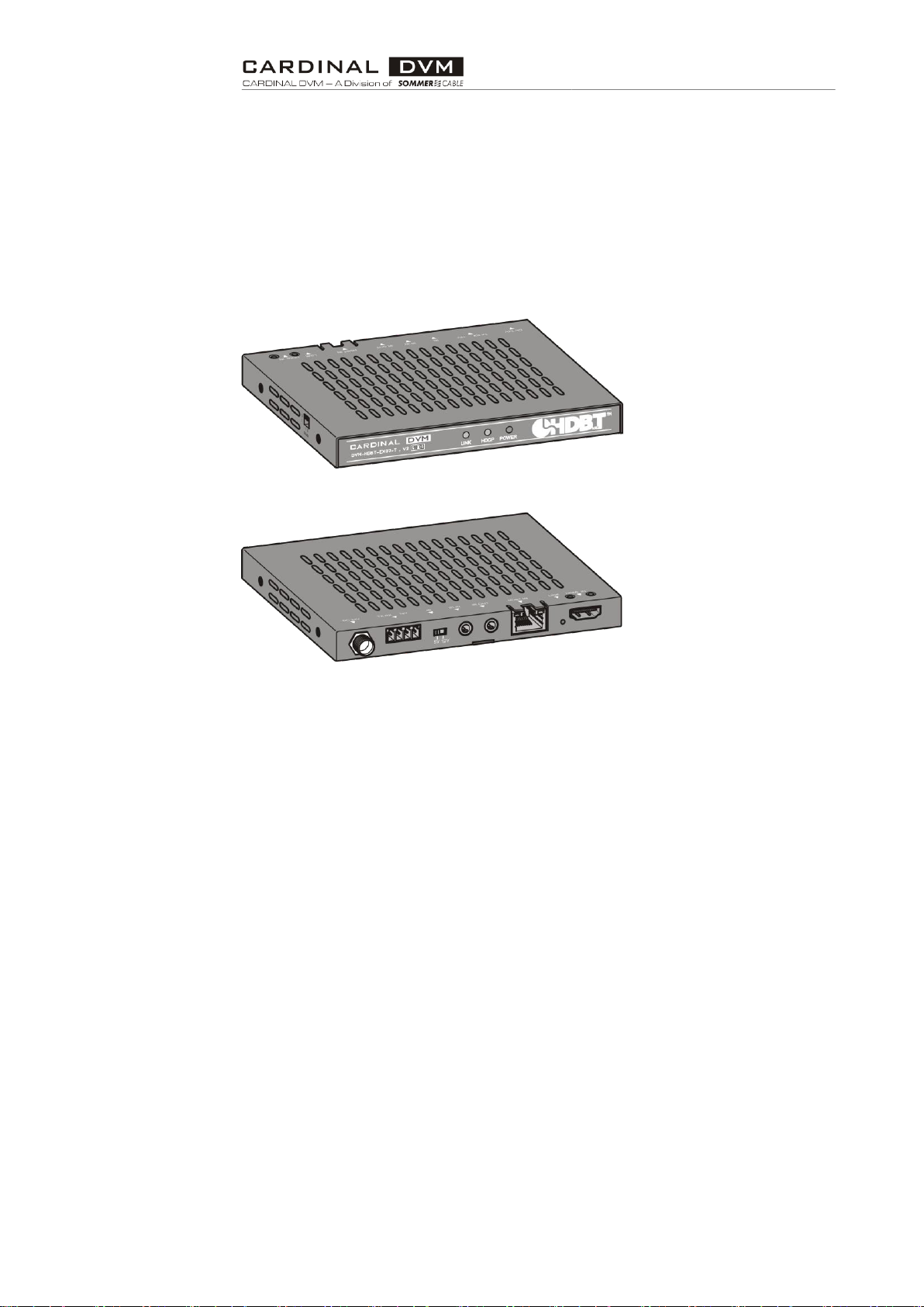
DVM-HDBT-EX07-T........................................................................................ 6
DVM-HDBT-EX07-R....................................................................................... 7
Task and function............................................................................................ 8
Information on the type plate........................................................................... 8
Technical data ................................................................................................ 9
Storing and transporting the product........................................................ 9
Unpacking the product and checking the scope of delivery..................... 9
Attach the HDMI cable............................................................................. 10
Connecting the product........................................................................... 10
Maintain the product................................................................................ 11
Disposing of the product......................................................................... 11
Warranty declarations ............................................................................. 11
Notices regarding these instructions and the
manufacturer
3
Notices regarding these instructions and the
manufacturer
These instructions will help you to use the "CARDINAL DVM-HDBT-EX07"
products safely. The "CARDINAL DVM-HDBT-EX07" products are referred to
as "product" in the following.
Keep these instructions available
These instructions are part of the product.
Always keep the instructions on the product.
Pass on the instructions if you sell the product or pass it on in any other
way.
Design features of these instructions
Various elements of these instructions have fixed design features. As a result,
you can easily differentiate the following elements:
Normal text
•First-level enumeration
Action steps
Tips contain additional information.
Copyright
These instructions contain information that is subject to copyright. These
instructions may not be copied, printed, filmed, processed, duplicated or
distributed in any form, either in whole or in part, without the prior written
permission of Sommer Cable GmbH.
©2021 Sommer Cable GmbH
All rights reserved.
Manufacturer’s address
Sommer Cable GmbH
Humboldtstraße 32-36
75334 Straubenhardt
Germany
Phone: +49-7082-49133-0
Fax: +49-7082-49133-11
E-mail: info@sommercable.com
Web: www.sommercable.com

Safety
4
Safety
Intended use
The product is an HDBaseT TX/RX Kit using smart CSC (Color Space
Conversion) technology with no latency to enable HDR and 4K/60Hz 4:4:4
video signal extension over HDBaseT.
The product is intended for use in closed buildings.
Intended use also includes compliance with the accident prevention
regulations and the statutory regulations and standards applicable at the place
of use.
Intended use also comprises reading and understanding these instructions, as
well as observing and following all information therein, especially the safety
instructions.
Any other use is not deemed to be intended.
Basic safety instructions
Severe or fatal injuries due to electric shock are possible.
Use only original CARDINAL DVM 24V DC power supplies like DVM-HDBT-
EX07-P to power the units. Void of warranty and potentially expose the user
to dangerous voltages resulting in an electrical shock could happen in case
of using wrong power supplies.
Do not expose the device to water, moisture, or liquids. Possible electric
shock may result as well as failure of the unit to operate.
Preventing material damage
Install the product in a dust-free environment.
Install the product protected against moisture, vapors, splash water and
wetness.
Install the product in a place protected from direct sunlight.
Do not install the product in the immediate vicinity of heat sources.
Use the product at ambient temperatures between 0 °C and 35 °C.
The transmission distances of HDMI over TP cables are measured using
AWG23/1 CAT6 a cable.
EIA/TIA-568-B termination for TP cables is recommended for better
performance.
Do not use 568A/568B standard mixed TP cable (cross-over cable) because
there are 2 pairs swapped, this will make POE OVER-CURRENT and
damage POE components. Use straight-through TP cable (both RJ45
headers are 568A or 568B standard).
Power up the device after connections of source, sink and CAT cable.
To reduce the interference among the unshielded twisted pairs of wires in
TP cable, do not run HDBaseT / Zone Cat5e/6/6a cabling with or in close

Description
5
parallel proximity to mains power cables. Shielded TP cables can be used to
improve EMI problems, which is worsen in long transmission.
Because the quality (AWG and also shielding) of TP cables have a major
effect on the transmission length limit and how good the received picture
quality is, the actual transmission range is subject to one’s choice of CAT
cables
Do not disassemble the device for any reason. Doing so will void the
product warranty. Also, our unique case is an integral part of the design of
this unit and is responsible for cooling and circuitry shielding. Any
modifications to this case will potentially cause malfunction and product
failure.
Personnel qualification
The instructions are intended for assembly and configuration personnel. The
following knowledge is required by assembly and configuration personnel:
•Knowledge in computer, network and media technology
•Knowledge and experience in assembly and configuration
Description
Scope of delivery
Depending on the order, the following may be included the scope of delivery:
•DVM-HDBT-EX07-T
•DVM-HDBT-EX07-R
•RS232 adapter-cable, Euroblock–Sub-D09
•IR receiver cable with ⅛" Minijack, 5 V
•Power supply (24 V/1A DC, Screw Connector)
•IR emitter cable with ⅛" TRS Minijack, 5 V
•mounting bracket with PH screws
Necessary accessories
CAT5/CAT6/CAT7 network cable is necessary for connecting the units.
Description
6
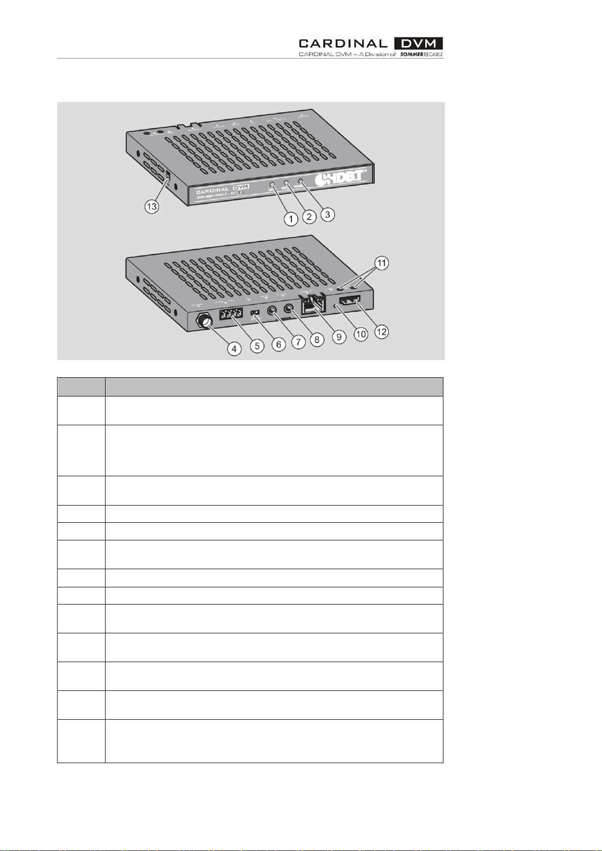
DVM-HDBT-EX07-T
No.
Designation
1
LINK LED indicator
Lit green when HDBaseT connecting between TX and RX
2
HDCP LED indicator
Lit green when signal with HDCP
flash when signal without HDCP
off when no source connected
3
Power LED indicator
Lit red when getting power
4
Power port (24 V/1A DC adapter to power the unit)
5
RS232 port (x 4-pin phoenix terminal connector)
6
IR selection switch
Switch to right side (12 V) or left side (5 V) to select IR
7
IR in port (3.5 mm stereo phone-jack, connect to IR receiver cable)
8
IR out port (3.5 mm mono phone-jack, connect to IR emitter cable)
9
HDBT output
RJ45 connector. Connect to HDBaseT input on DVM-HDBT-EX07-R
10
HDMI input LED indicator
Lit if the HDMI input is active
11
HDMI cable lock
Fix the HDMI cable with screw (see page 10)
12
HMDI input port
Connect to HDMI source device, such as DVD, TV box
13
Mode DIP Switch, 2 pin (UP=0, DOWN=1)
00: RS232 pass through
01: Valens firmware upgrade
Description
7
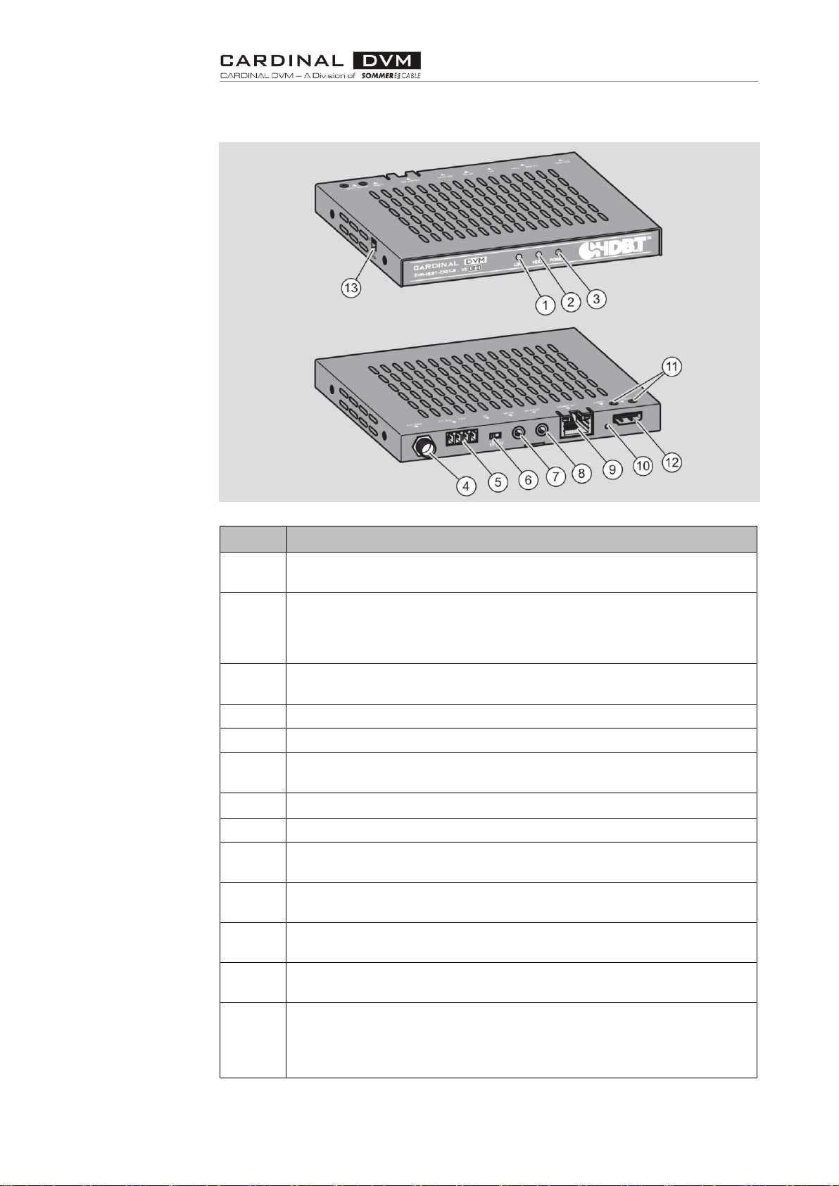
DVM-HDBT-EX07-R
No.
Designation
1
LINK LED indicator
Lit green when HDBaseT connecting between TX and RX
2
HDCP LED indicator
Lit green when signal with HDCP
flash when signal without HDCP
off when no source connected
3
Power LED indicator
Lit red when getting power
4
Power port (24 V/1A DC adapter to power the unit)
5
RS232 port (x 4-pin phoenix terminal connector)
6
IR selection switch
Switch to right side (12 V) or left side (5 V) to select IR
7
IR in port (3.5 mm stereo phone-jack, connect to IR receiver cable)
8
IR out port (3.5 mm mono phone-jack, connect to IR emitter cable)
9
HDBT output
RJ45 connector. Connect to HDBaseT input on DVM-HDBT-EX07-R
10
HDMI input LED indicator
Lit if the HDMI input is active
11
HDMI cable lock
Fix the HDMI cable with screw (see page 10)
12
HMDI input port
Connect to HDMI source device, such as DVD, TV box
13
Mode DIP Switch, 2 pin (UP=0, DOWN=1)
00: RS232 pass through
01: Valens firmware upgrade
10: MCU firmware upgradefirmware upgrade

Description
8
Task and function
The Product is an HDBaseT TX/RX Kit using smart CSC (Color Space
Conversion) technology with no latency to enable HDR and 4K/60Hz 4:4:4
video signal extension over HDBaseT. The kit supports standard bi-directional
POH (Power over HDBaseT). It provides HDMI transmission up to 230ft (70
m) for 1080p video, and up to 130ft (40 m) for 4K HDR over CAT5e/6a/7
cable, as well as bi-directional IR and RS232 control signals. It delivers a cost-
effective solution for HDMI extension, with surface mounting hardware for
easy installation. The DVM-HDBT-EX07 is ideal for residential applications
with the latest emerging 4K/UHD and HDR sources and displays. It is
compatible with all video resolutions, audio formats, and color space formats
supported in the HDMI 2.0a specification, plus the ability to pass metadata for
HDR content.
Smart CSC is a technology that can convert 6G video to 3G at TX unit and
recover 3G to 6G at RX unit. The RX unit can smartly output 6G or 3G video
depends on the sink device capacity.
Information on the type plate
The type plate is glued to the power supply unit housing. It contains the
following information:
•Type designation of the power supply unit
•EAN code
•Serial number
•Disposal symbol
•CE marking (The product complies with the standards listed in the enclosed
declaration of conformity.)

Storing and transporting the product
9
Technical data
Products:
DVM-HDBT-EX07-T
DVM-HDBT-EX07-R
HDMI Bandwidth
600 MHz/ 6 Gbps
600 MHz/ 6 Gbps
HDBaseT Bandwidth
340 MHz/10.2 Gbps
340 MHz/10.2 Gbps
Video Input Connectors
1 × HDMI Type A, 19-pin
female, locking
1 × HDBaseT RJ45
connector
Video output
Connectors
1 × HDBaseT RJ45
connector
1 × HDMI Type A, 19-pin
female, locking
RS232 serial port
1 × 4-pin phoenix terminal
connector, Green
1 × 4-pin phoenix terminal
connector, Green
IR Input ports
1 × 3.5 mm stereo jack
1 × 3.5 mm stereo jack
IR Output ports
1 × 3.5 mm mono jack
1 × 3.5 mm mono jack
Operating Temperature
32 °F to 104 °F
(0 °C to 40 °C)
32 °F to 104 °F
(0 °C to 40 °C)
Storage Temperature
–4 °F to 140°F
(–20°C to 60°C)
–4 °F to 140°F
(–20°C to 60°C)
Power supply
24 V/1A DC, Screw
Connector
24 V/1A DC, Screw
Connector
Shipping Weight
0,4 kg
0.4 kg
Dimensions W × H × D
134 mm × 16 mm × 110
mm
134 mm × 16 mm × 110
mm
Specifications are subject to change without notice.
Storing and transporting the product
Store the product in its original packaging.
Transport the product in its original packaging.
Unpacking the product and checking the scope
of delivery
Remove the parts of the product from the original packaging.
Keep the original packaging for later storage or possible return.
Check whether all parts of the product were delivered; for more information,
see page 5.
Check that the parts are in perfect condition.
Contact the manufacturer if parts are missing or damaged.
Attach the HDMI cable
10
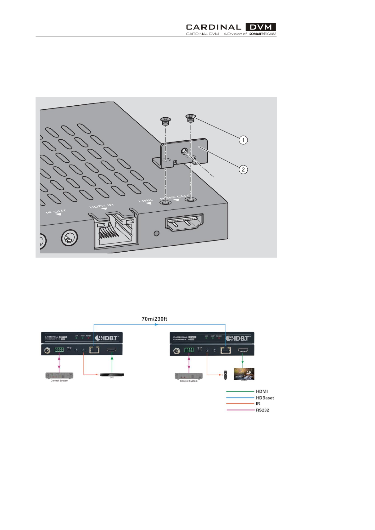
Attach the HDMI cable
Attach the bracket (2) to the product with to screws (1) as shown in the
following figure.
Fix the HDMI cable with a screw (the screw is not shown).
Connecting the product
Connect the product as shown in the following figure.
The following figure shows the product as an example.

Maintain the product
11
Maintain the product
Clean this Product with a soft, dry cloth.
Disposing of the product
At the end of its service life, you must dispose of the product and its
accessories in an environmentally friendly manner.
Return the product to the manufacturer in its original packaging.
Alternatively, dispose of the product with an approved waste disposal
company.
Observe and comply with the applicable regulations.
In case of doubt, contact your city or municipal administration.
Warranty declarations
Sommer Cable GmbH grants a manufacturer's warranty of two years from the
date of purchase (proof of purchase receipt) on all parts included in the scope
of delivery within the scope of legal regulations. Improper handling or incorrect
use shall exempt liability for defects.
This manual suits for next models
1
Table of contents
Other Sommer Cable Receiver manuals


