Aventura WRS-ANK-58WP User manual

*K]:LUHOHVV7UDQVPLWWHU5HFHLYHU
:56$1.:3
352'8&70$18$/
$YHQWXUDTechnologies
KWWS$YHQWXUD&&79FRP

2
TABLE OF CONTENTS
TABLE OF CONTENTS……………….…..………………………..………………………..1
SAFETY NOTICE………………..…………………………...……………………………….2
INTRODUCTION……………………..…………..…………………………………………....2
PARTS LIST…………..……………………..…………………..…………………………….3
PRE-INSTALLATION……………………………………….……………..……………….…3
CONDUCTING A BENCH TEST…........................................................................3
IDENTIFY LINE-OF-SIGHT…………….................................................................3
UP IN THE CLEAR……………………………………………………………………...3
GROUND PLANE…………...…………………………………………………………..3
TREES GROW.......................................................................................................4
UNUSUAL TRAFFIC……………………………………………………………...….…4
OBSTRUCTED LINE OF SIGHT……………………………..………………………..4
INSTALLATION LINE-OF-SIGHT………………….…………...………….………… 5
THINGS THAT BLOCK TRANSMISSION……………………………….……………5
VIDEO CABLE INSTALLATION……………………………………………………..……...6
AUDIO CABLE INSTALLATION………………..……….…………………………………..7
POWER SUPPLY CONNECTION………………………..………………………………….8
CHANNEL SELECTION……………………………………..…………………………….…8
CONDUCTING A BENCH TEST……………………………………………..……….…..…8
INSTALLATION………………………………………………………..…………………….10
TIPS & TROUBLE SHOOTING…………..………………………..……………………….1
SPECIFICATIONS……………………………………………..…………………………….1

3
SAFETY NOTICES
I. THIS DEVICE COMPLIES WITH FCC RULES PART 15. OPERATION IS SUBJECT TO THE
FOLLOWING TWO CONDITONS:
(1) This device may not cause harmful interference, and
(2) This device must accept any interference, including interference
that may cause undesired operation of the device
II. In order to comply with the FCC/IC adopted RF exposure requirements, this transmission system
will be installed by an authorized professional installer of $YHQWXUD Technologies. Installation
of all antennas must be performed in a manner that will provide at least 23cm clearance from the
front radiating aperture, to any user or member of the public.
III. This is NOT an intrinsically safe device. Do not take into area where intrinsic safety is required.
Bodily harm may result if warning is ignored.
IV. DO NOT OPERATE TRANSMITTER WITHOUT ANTENNA CONNECTED TO ANTENNA PORT.
Failure to do so will result in damage to the unit and void the warranty.
V. DO NOT OPERATE THE :56$1.:3 SYSTEM WHEN the Transmitter & Receiver are closer than
WHQfeet to each other. The devices may not work properly and permanent damage can occur.
VI. The :56$1.:3 has been certified by the FCC for use with other products without further
certification (as per FCC section 2.1091.) Changes or modifications not expressly approved by
$YHQWXUD Technologies could void the user’s authority to operate the equipment.
INTRODUCTION
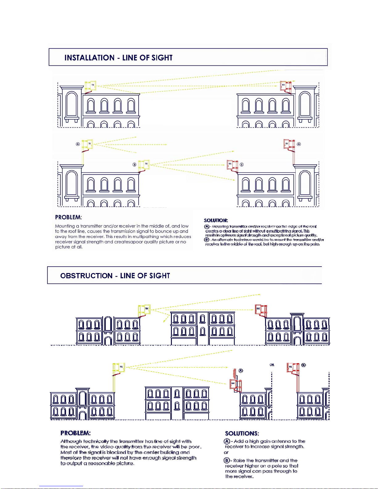
Designed with the harshest environments in mind, the robust :56$1.:3 delivers
high resolution, real time video in applications ranging from a few hundred feet up to
many miles, depending on system. Its rugged IP-67 all-weather enclosure transmits in
applications where trenching cable may not be possible, convenient or economical.
Operating in the unlicensed 5.8GHz ISM band, this unit features eight user selectable
channels and includes a universal mounting bracket system for a variety of mounting
scenarios.
ADVANTAGES
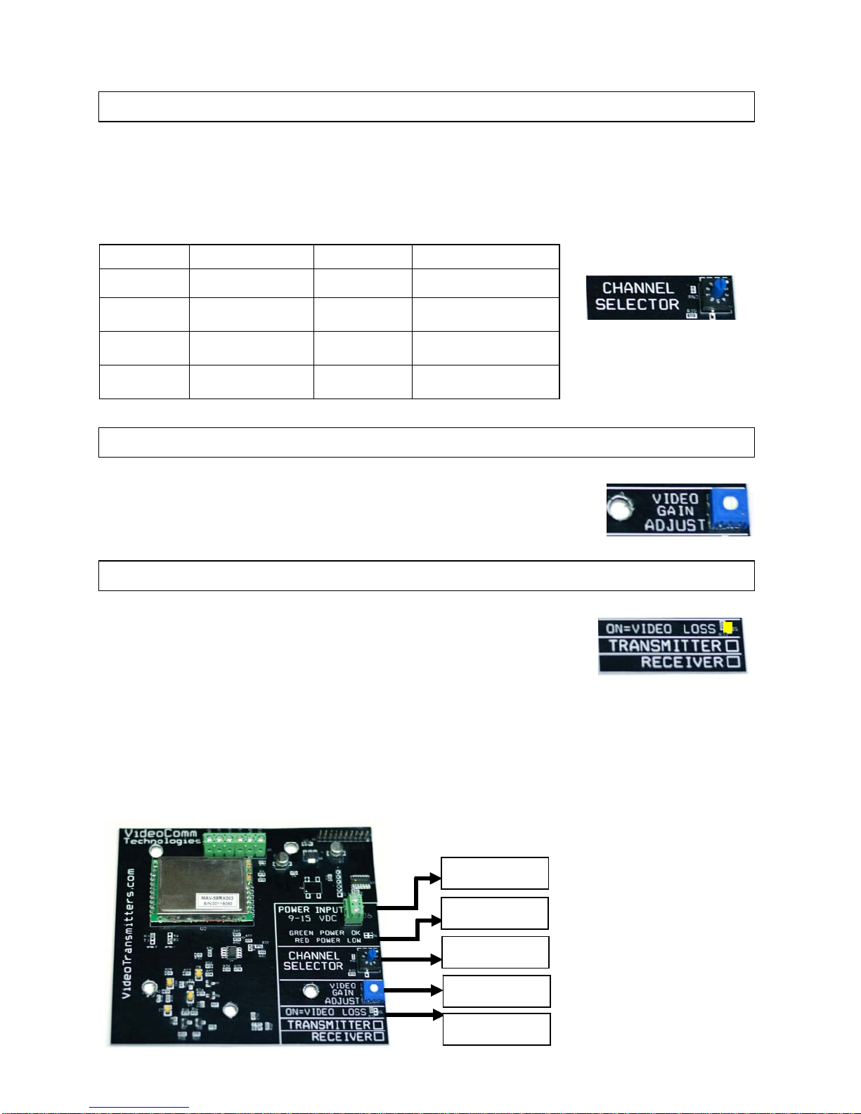
New & Improved power and video signal LED indicators for a quick and
easy installation
8 user selectable channels for multiple camera applications
Delivers high resolution, Real Time video from 2,000 feet up to 4 Miles
Not susceptible to wireless 802.11b/g data networks and other devices
Rugged IP-67 protective enclosure for extreme all weather environments
Perfect for commercial, industrial, scientific, law enforcement and government
video security applications.

4
PARTS LIST
Please inspect the packaging carefully to ensure you have received all the necessary
parts and accessories listed. Refer to the following chart to determine which parts are
included with your product. If any parts are missing or damaged, contact $YHQWXUD
Technologies, Customer Service or your re-seller immediately.
PRE INSTALLATION
Conducting a Bench Test
To arrive on the job site confident that all of your devices will install with the
least amount of on-site effort, first verify that all components of the system are
in good working order and set to the matching channels (see page 7).
Identify line-of-sight
Ensure there is a clear, unobstructed view between the transmitter and
receiver. Depending on the height of the building or structure, you must
consider the path that the wireless video will travel between the transmitter &
receiver to prevent interference from buildings or other obstacles.

5
Up & in the clear
The radio waves coming from your :56$1.:3 antennas do not shoot
out like a laser beam, rather they radiate from the antenna like a flash light
beam. Therefore the transmitter and receiver should both be up and in the
clear. $YHQWXUD recommends a minimum mounting height of 15 feet above
any obstructions which may block or interfere with the transmission signal.
Ground Plane
If the radio devices are not mounted high enough above obstructions, the signal
strength will be seriously reduced; therefore your distance will be reduced. The
signal will literately bounce up and away from your intended target. This is
known as a negative ground plane effect. The ground plane could not only be
the ground you stand on, but could also be the rooftops of cars or distant
buildings. If we have a choice, place the transmitter / receiver enclosures, or if
external antenna, on the edge of the roof looking AWAY from the building,
rather than installing them in the middle of the roof.
Trees Grow!
If we install the video link in the winter, the leaves that come out in spring may
eliminate your wireless link. Are you trying to transmit through trees? Then you
will need to seriously consider how much range will be lost. A field test is
always the best way to find out. Speak to a $YHQWXUD Technologies Tech for
a possible solution.
Unusual Traffic
Watch out for unusual traffic in your transmission path. Tractor-trailers or other
large vehicles may be a factor if trying to transmit over a highway. Metal
obstructions between the antennas cannot be ignored including electrical
transmission lines that may not be obvious in the distance.

6

7
Things that block transmission
Steel, or anything with steel in it such as reinforced concrete (rebar) or metal window
screens, or a tool-room cage. Aluminum siding, and energy-saving foil on the
insulation in the walls are sneaky killers for radio waves. Some metallic paints or
metallic wallpapers also block signals.
Mirrors block transmission, because the “mirror” consists of a metallic backing on the
glass.
Windows that contain lead can kill radio transmission; also windows that are UV
coated may have thin metal energy-saving film.
High Voltage transmission lines (physically they look small, but for video
transmission purposes, they might as well be 6-foot diameter metal sewer pipes.
Other materials like brick, drywall or wood, will also cut down on the signal,
depending on water content.
VIDEO & AUDIO CABLE TERMINATION
Do not use video or audio cable that is less than ¼” in diameter, as this may not
allow a proper seal when the cable gland is tightened. If a tight seal is not made
between the cable gland and the video cable, there is a chance of water leaking
into the enclosure, causing serious damage and voiding the warranty.
Loosen the desired cable gland.
Feed the video and audio coax cable starting from the outside of the
IP-67 enclosure through the cable gland hole. $YHQWXUD Technologies
recommends the use of RG-59 or higher grade coaxial cable for video
and audio terminations. At this time, attach your BNC-Male connector to
your Coax Cable and terminate inside.
Tighten the cable gland to ensure a water tight seal.

8
TERMINATING EXTERNAL ANTENNA – :56$1.:3
Carefully thread the RF cable SMA-Male connector
onto the receiver’s SMA-Female Input and tighten.
Tighten the grommet to seal the cable
to prevent water damage.
SEAL UN-USED GROMMETS
If there are cable glands not being used this means
that water can enter the enclosure, causing damage.
To prevent this from happening, use the included
black plugs to seal off any unused cable glands.
If you do not tighten the cable gland you do not have a water
tight seal which may cause water damage and void the warranty
POWER SUPPLY CONNECTION
WARNING! Unplug power supply before connecting raw leads to power input
terminal strip. An electrical short can occur, causing harmful damage to the
unit. Each unit is Polarity Protected.
Turn the small cable gland counter clock wise to loosen.
Feed the power cable wire through the cable gland hole.
Insert wire leads into the polarity protected power
input terminal and secure. (See Figure A) FIGURE A
Assuming that the power wire leads have been terminated properly,
plug in the power supply to an available AC source.
If the GREEN LED power level indicator light turns ON, your power is
within the acceptable operating range. If the system is receiving less
than 9VDC, the RED LED power indicator light will turn ON and the
system will not function. (See Figure B)
Now tighten the grommet to seal the cable
to prevent water damage.
FIGURE B

9
CHANNEL SELECTION
Both the transmitter and receiver must be set to the same channel. On the inside of the
transmitter and the receiver, you will find an 8-Channel rotary switch. Choose desired
channel and set the rotary switch accordingly. Ensure both the transmitter and receiver
have the same channel settings.
FIGURE C
VIDEO GAIN ADJUSTMENT
FIGURE D
VIDEO LOSS LED INDICATOR
Transmitter: If the Yellow LED video loss indicator is ON -
the transmitter is not receiving video from the camera. Check
your video source, cables and connections to the transmitter.
FIGURE E
Receiver: If the Yellow LED video loss indicator is ON – no video is being received from
the transmitter.
** Confirm that both the transmitter and receiver are set to the same channel
** There may not be enough RF signal for the receiver to demodulate the video
Frequency Frequency
CH # 1 5.733 GHz CH # 5 5.809 GHz
CH # 2 5.752 GHz CH # 6 5.828 GHz
CH # 3 5.771 GHz CH # 7 5.847 GHz
CH # 4 5.790 GHz CH # 8 5.866 GHz
The system has been carefully calibrated by the factory, however
video gain adjustments may be made if required. Contact
$YHQWXUD Technologies Technical support for assistance.
FIGURE B
FIGURE C
FIGURE D
FIGURE E
FIGURE A

10
INSTALLATION
These systems are designed with embedded directional antennas and aim out of the
front face of the enclosure. It is important for both antennas to be “looking at each other”
and ideally mounted at the same approximate height from the ground. We recommend
a mounting height no less than 15 feet above any obstruction.
Wall Mounting
Fasten the base plate of the
mounting brackets to the wall using
four screws or bolts (not included).
Ensure the mount is secure and
capable of supporting the weight of
the transmitter or receiver.
See Step 2
Pole Mounting
Fasten the base plate of the
mounting brackets to the pole
with the included hose clamps.
See step 2
Attach the pivot plate (of the mounting brackets) to the
base plate using four mounting screws – Included
Insert and secure the four mounting screws into each
corner of the IP-67 enclosure. Ensure the grommet
seal plugs a point down to avoid water damage and
void the warranty.
Replace the front cover of the transmitter or receiver.
Do not over tighten the screws as this can crack or
cause damage to the front cover of the unit. Verify all
cable glands are snug, and have a water tight seal.
Adjust the angle of both the transmitter and receiver to
ensure proper alignment and secure in place using the
included mounting screws.

11
TIPS & TROUBLE SHOOTING
Snow on the Monitor
If there is snow or noise on your monitor this is a good indication that the receiver is
receiving a weak signal.
To correct an image that has a lot of noise (snow) a number of things can be done.
Move the transmitter and receiver closer together.
Eliminate obstructions between the transmitter and receiver.
Add a high gain antenna to the receiver end to increase receive sensitivity.
Interference
We strongly recommend that you always conduct a temporary setup of any wireless
equipment before systems are permanently mounted. As we are sharing a radio
frequency that is considered part of the public band, we do not have any entitlement to
that frequency and must accept interference if it exists.
Examples of RF Interference
Other 5.8GHz video transmitters in your area.
5.8GHz wireless data network, LAN or WAN.
Proximity to some consumer products may be a source of interference.
Examples include cordless phones, consumer data transceivers for wireless
internet, and Bluetooth devices.
Other Examples of Interference Not Related to Wireless
Improper line-of-sight, installation or alignment of transmitters and receivers.
Power source ground loops.
Incorrect voltages to devices (too high or too low), including transmitters and
receivers.
Possible Solutions if Experiencing Interference
Change the channel of your transmitter or move your wireless video devices
farther away from the source of interference. Transmitters do not have to be
beside the camera source and the receivers do not have to be beside the
monitoring equipment.
Depending on the installation, use an existing building as a shield from
interfering sources.
Use separate regulated power supplies for each device.

12
SPECIFICATIONS
Operating Frequency 5.725GHz – 5.875GHz, 8 Selectable Channels
Radiated Power 50mV/m @ 3m
Range (Line-of-Sight) :56$1.:3 - Depends on optional antenna
7dB RX Antenna 2000ft
14dB RX Antenna 1 Mile
29dB RX Antenna 4 Miles
Transmitter Antenna Type 3dB Internal Fixed Directional Patch
Receiver Antenna TypeV2SWLRQDO
7dB Internal Removable Directional Patch
14dB Internal Removable Directional Patch
29dB External Removable Directional Parabolic
Receiver Sensitivity -84dBm
Video Format NTSC and PAL
Modulation FM - Frequency Modulation
Video Connector BNC Female @ 75 Ohms 1 Volt P–P
Stereo Audio Connector Left and Right BNC-F @ 600 Ohms 1 Volt P – P
Temperature Range -40 – 170 degrees Fahrenheit
Power Supplies 12 VDC@ 500mA - Model # 1250CLX
Current Consumption Tx: 170mA @ 12VDC Rx: 230mA @ 12VDC
Dimensions 7” x 7” x 4” OR 180mm x 180mm x 100mm
Mounting Bracket Two Universal Wall / Pole Mount - # BRK-250
Weight 8kg or 29oz each enclosure
FCC / IC / CE Approved Yes
Warranty One Year Limited Warranty
Table of contents
Other Aventura Receiver manuals
Popular Receiver manuals by other brands

Romantis Satellite Communications
Romantis Satellite Communications UHP-8000 General description and installation guide

AEORC
AEORC RX34 Series instruction manual

Harman Kardon
Harman Kardon AVR 130 quick start guide

Juniper
Juniper Day One+ ACX7024 manual

LG
LG LH-T363SD owner's manual

Yamaha
Yamaha RX-A 3070 quick start guide