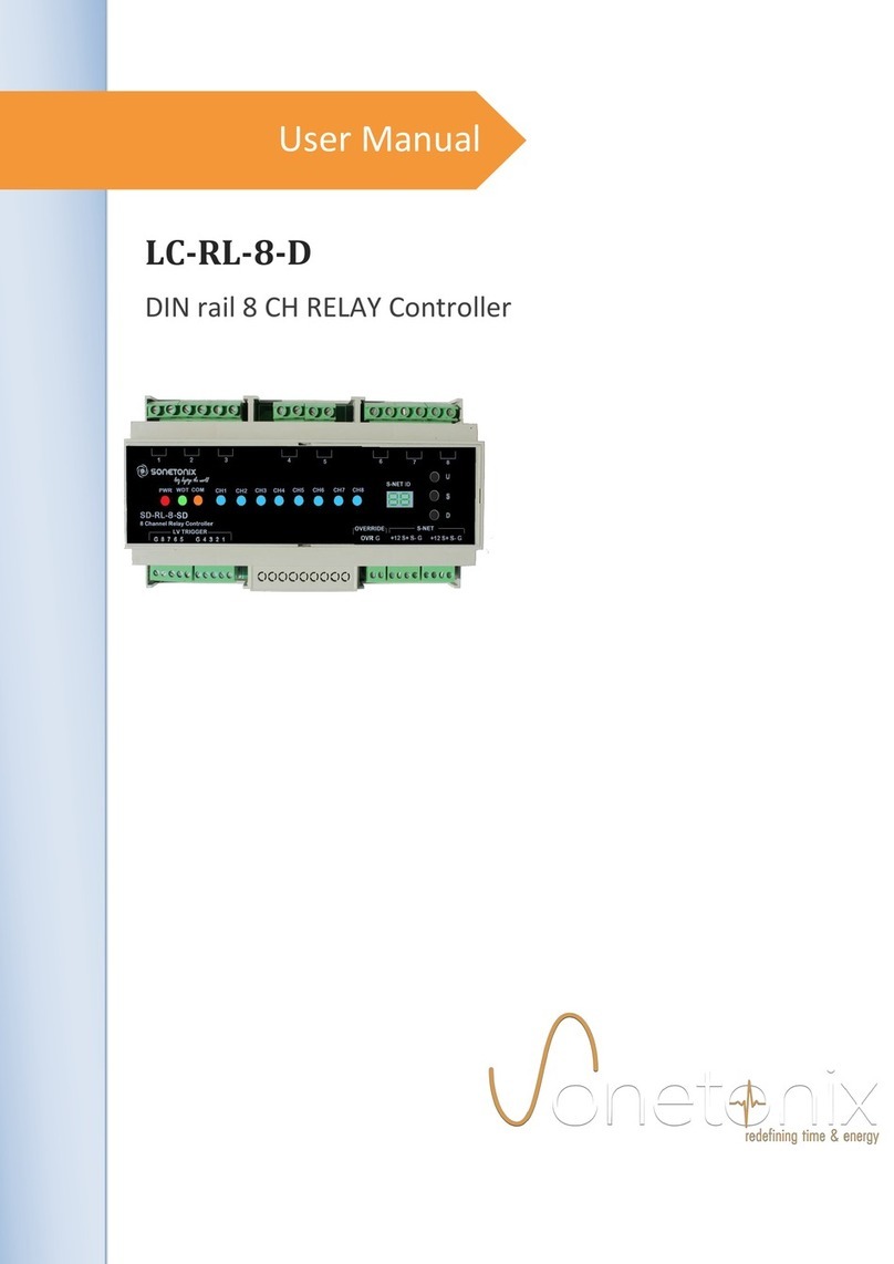
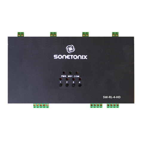
Sonetonix LC-RL-8-W User manual

User Manual
LC-RL-8-W
Wall Mount 8CH RELAY Controller

LC-RL-8-W User Manual
Sonetonix
Preface
Read this user manual carefully before using this product. Pictures shown in this manual is for
reference only, different model and specifications are subject to real product.
This manual is only for operation instruction only, not for any maintenance usage. The functions
described in this version are updated till January 2016. Any changes of functions and parameters
since then will be informed separately. Please refer to the dealers for the latest details.
Trademarks
Product model and its logo are trademarks. Any other trademarks mentioned in this manual are
acknowledged as the properties of the trademark owner. No part of this publication may be copied
or reproduced without prior written consent.
FCC Statement
This equipment generates uses and can radiate radio frequency energy and, if not installed and
used in accordance with the instructions, may cause harmful interference to radio
communications. It has been tested and found to comply with the limits for a Class B digital device,
pursuant to part 15 of the FCC Rules. These limits are designed to provide reasonable protection
against harmful interference in a commercial installation.
Operation of this equipment in a residential area is likely to cause interference, in which case the
user at their own expense will be required to take whatever measures may be necessary to
correct the interference
Any changes or modifications not expressly approved by the manufacture would void the user’s
authority to operate the equipment.

LC-RL-8-W User Manual
Sonetonix
SAFETY PRECAUTIONS
To insure the best from the product, please read all instructions carefully before using the device.
Save this manual for further reference.
Unpack the equipment carefully and save the original box and packing material for possible
future shipment
Follow basic safety precautions to reduce the risk of fire, electrical shock and injury to persons.
Do not dismantle the housing or modify the module. It may result in electrical shock or burn.
Using supplies or parts not meeting the products’ specifications may cause damage,
deterioration or malfunction.
Refer all servicing to qualified service personnel.
To prevent fire or shock hazard, do not expose the unit to rain, moisture or install this product
near water.
Do not put any heavy items on the extension cable in case of extrusion.
Do not remove the housing of the device as opening or removing housing may expose you to
dangerous voltage or other hazards.
Install the device in a place with fine ventilation to avoid damage caused by overheat.
Keep the module away from liquids.
Spillage into the housing may result in fire, electrical shock, or equipment damage. If an object
or liquid falls or spills on to the housing, unplug the module immediately.
Do not twist or pull by force ends of the optical cable. It can cause malfunction.
Do not use liquid or aerosol cleaners to clean this unit. Always unplug the power to the device
before cleaning.
Unplug the power cord when left unused for a long period of time.
Information on disposal for scrapped devices: do not burn or mix with general household waste,
please treat them as normal electrical wastes.

LC-RL-8-W User Manual
Sonetonix
Content
1. PRODUCT OVERVIEW.................................................................................................................................................................. 1
1.1 Key Features.............................................................................................................................................................................. 1
1.2 Override Input............................................................................................................................................................................ 2
1.3 Front panel..................................................................................................................................................................................2
1.4 Loads...........................................................................................................................................................................................2
1.5 S-NET..........................................................................................................................................................................................2
2. TECHNICAL SPECIFICATIONS....................................................................................................................................................3
2.1 Florescent/LED Dimmer Electrical Specifications................................................................................................................3
2.2 Power Requirements................................................................................................................................................................ 3
2.3 Connections................................................................................................................................................................................3
2.4 Controls and Indications...........................................................................................................................................................3
2.5 Mechanical specifications........................................................................................................................................................ 4
2.5.1 Enclosure............................................................................................................................................................................4
2.5.2 Environmental.................................................................................................................................................................... 4
2.5.3 Dimensions and weight.................................................................................................................................................... 4
3. APPLICATION AND WIRING DIAGRAM..................................................................................................................................... 5
4. MANUAL CONTROL........................................................................................................................................................................6
4.1 Programming the S-NET ID.....................................................................................................................................................6
4.2 Changing the Channel level / status.......................................................................................................................................6
5. S-NET COMMUNICATION............................................................................................................................................................. 7
5.1 Communication parameters.....................................................................................................................................................7
5.2 S-NET Commands.................................................................................................................................................................... 7
5.3 Examples.................................................................................................................................................................................... 8
6. TROUBLESHOOTING.....................................................................................................................................................................8
7. AFTER-SALES SERVICE...............................................................................................................................................................9

LC-RL-8-W User Manual
Sonetonix 1
1. Product Overview
Sonetonix LC-RL-8-W, Relay
module incorporates 8ch relays that can be
connected to control controllable devices.
The RELAY controller can be interfaced
Using our Touch Keypads or Android App
to control from anywhere in the room. Four
channels of Relay controller can be used in
non-dimmable lighting control, screen
control, Water fountain motor control (up to
0.5Hp motor), Gate/Shutter control and etc.
Maximum of 10A load can be connected to
each channel. Provision to store and re-call
up to 16 pre-set scenes. As with other
Sonetonix products, all S-NET commands
are available to use and program the Device
as per user needs thus extending its
functionality.
1.1 Key Features
- 8 Channels RELAY Controller, standard type @10A per channel
- Power switching
- Used in non-dimmable lighting control, screen control (up to 0.5Hp motor) etc.
- Supports 16 scenes with internal memory
- Low voltage control interface for each channel
- Restores channel status upon power reset
- Configurable START time for each channel, allows to set delay to start the switching at
required time
- S-NET ID programming sequence with front panel switches to set the Device’s S-NET ID
manually
- Front panel switches to operate each channels manually
- Watchdog LED on front panel blinking @1 sec Indicates normal working condition of the
Device
- Status indication LEDS for each channel
- S-NET Communication, using S-NET protocol enables the relay Controller to be
connected with other SONETONIX Lighting/ Dimming modules for a complete Automation
Solution
- Easy installation with Wall mounting
Fig 1 LC-RL-8-W, Wall Mount 8 channel RELAY
Controller

LC-RL-8-W User Manual
Sonetonix 2
1.2 Override Input
An override input is provided to allow an external contact closure to momentarily override
the control system program and set all channels output to its override pre-set state.
1.3 Front panel
Four tactile switches on the front panel provide two functionalities. One, the Device’s S-
NET id can be programmed manually at any time, using the CH1 (1) and CH2 (2) keys. The other
functionality of these switches is to navigate through the channels manually along with channel
status indication LEDS.
1.4 Loads
Two pin detachable terminal blocks on the rear side for each channel to control the
controllable devices. Live IN (230VAC Mains @50hz) to be connected on Pin 1 and Live output
to be taken from Pin 2 and connect to Load Live.
1.5 S-NET
The LC-RL-8-W communicates with all Sonetonix products or third party units via S-NET.
A pair of S-NET terminal blocks, allow for easy daisy-chaining of several DIN rail Series
automation control modules. 12VDC, S+, S- and Ground should be connected in each S-NET
terminal.

LC-RL-8-W User Manual
Sonetonix 3
2. Technical Specifications
2.1 RELAY Controller Electrical Specifications
Parameter
Value
Unit
Operating Voltage(@50hz)
220-240
VAC
Max Power per channel
2300
W
Max Load current per channel
10
A
Module Total current
80
A
Operating Temperature
0 – 45
°C
Table1. Relay controller Electrical specifications
2.2 Power Requirements
S-NET Power Usage:6 Watt (0.5A @12Volts)
2.3 Connections
CHANNELS (1-8): (4) 2-pin 5.08 mm detachable terminal blocks with SPST relay switch circuit
@10A per channel
LV TRIGGERS (G, 1-8): (1) 5-pin 5.08mm detachable terminal block to provide low voltage
trigger to each channel
S-NET: (1) 4-pin 5.08mm detachable terminal blocks for S-NET communication
2.4 Controls and Indications
PWR: (Red) Illuminates when DC power is applied on S-NET
WDT: (Green) Blinking @ 1 sec Indicates normal working condition of the Device
COM: (Orange) Blinks during S-NET communication
CH1 TO CH8: (Red) Channel status indication LEDs
1-8: Miniature tactile switches to set S-NET ID or control channels manually

LC-RL-8-W User Manual
Sonetonix 4
2.5 Mechanical specifications
2.5.1 Enclosure
Wall Mount dark Gray metal sheet enclosure
2.5.2 Environmental
Operating Temperature: 0° to 45°C
2.5.3 Dimensions and weight
Parameter
Value
Unit
Height
4.13
Inches
Width
9.05
Inches
Depth
1.57
Inches

LC-RL-8-W User Manual
Sonetonix 5
3. Application and wiring diagram

LC-RL-8-W User Manual
Sonetonix 6
4. Manual Control
4.1 Programming the S-NET ID
For any communication to take place with the LC-RL-8-W, it needs to be programmed with
a unique S-NET ID (1 to 230).
The S-NET ID can be set manually using the following procedure
Step 1: Press and hold the (1) Setup switch on front panel for 5 seconds
Step 2: The Watch dog LED stops blinking and the device enters in to programming mode
Step 3: The default S-NET ID will be displayed in terms of WDT LED blinking sequence.
Step 4: Press the (2) switches on front panel to set the S-NET ID number
Step 5: After choosing a suitable ID, press the (1) Set up Switch to enter in to normal mode, the
watchdog LED will flash a blinking sequence and enter in to Normal mode.
4.2 Changing the Channel level / status
Front panel 8 switches for control and configure the load status manually. Each channel’s
ON / OFF status is indicated on the Front panel LEDS
The load status for any channel can be changed manually by pressing corresponding tactile
switch.

LC-RL-8-W User Manual
Sonetonix 7
5. S-NET Communication
The LC-RL-8-W can be connected in S-NET with other Automation modules using
RS485 serial interface. The signal connection is shown in Fig 1. Wiring diagram
5.1 Communication parameters
Parameter
Description
Signal Level
RS-485 compliant
Synchronisation method
Asynchronous
Baud Rate
38400 bits / second
Parity
None
Data Bits
8
Stop Bits
1
5.2 S-NET Commands
Using the S-NET protocol command codes, various features of the LC-RL-8-W can
be controlled and used. The device control commands and channel control commands
are described here under.
Command
Description
Response
Get Device Info
<ID> $F2
$F5 <ID> <Device Type>
<Device model> $F5
Get New Device Info
$F0 $F2
$F5 <ID> <Device Type>
<Device model> $F5
Set New Device ID
$FE <ID> $F3 <new ID>$FD
$F5 <ID> <ch1 status> <ch n
status> $F5
Force Set Device ID
$FE $F4 <new ID> $00 $FD
$F5 <ID> <ch1 status> <ch n
status> $F5
Get Device Status
<ID> $F1
$F5 <ID> <ch1 status> <ch n
status> $F5
Turn ON all channels
$FE <ID> $FA $00 $FD
None
Turn OFF all channels
$FE <ID> $F9 $00 $FD
None
Set Load to ON
immediately
$FE <ID> <Ch.no> $01 $00 $00
$FD
None
Set Load to OFF
immediately
$FE <ID> <ch.no> $00 $00 $00
$FD
Multiple channels
control
$FE <ID> $F6 <no.of channels>
<ch1. Data>…..<ch n. Data>
$FD
None
Store scene
$FE <ID> $F7 <no.of channels>
<Scene.no> < ch1.
Data>….<ch n.data> $FD
None
Recall scene
$FE <ID> $F8 <scene. No>$FD
None
Set Load status after
delay
$FE <ID> <ch.no> $xx $00 $yy
$FD
None

LC-RL-8-W User Manual
Sonetonix 8
5.3 Examples
Command
Description
Get Device Info for ID 2
$02 $F2
Set New Device ID to ID 3 as 8
$FE $03 $F3 $08 $FD
Force Set Device ID of a new ID to 01
$FE $F4 $01 $00 $FD
Turn ON all channels to device ID 05
$FE $05 $FA $00 $FD
Turn OFF all channels to device ID 05
$FE $05 $F9 $00 $FD
Get Device Status of device ID 01
$01 $F1
Set Load 1 to ON immediately ID 01
$FE $01 $01 $01 $00 $00 $FD
Set Load 1 to OFF immediately ID 01
$FE $01 $01 $00 $00 $00 $FD
Set Load 1 to ON after 5 seconds ID 02
$FE $02 $01 $01 $00 $05 $FD
Store scene to device ID 01 – ch1 ON ch4 ON with
scene number as 05 (2 channels in scene)
$FE $01 $F7 $02 $05 $01 $01 $00
$00 $04 $01 $00 $00 $FD
Recall scene 5 for device ID 01
$FE $01 $F8 $05 $FD
Set multiple control command to ON load 1 and
Off load 2 after 5 seconds ID 01
$FE $01 $F6 $02 $01 $01 $00 $00
$02 $00 $00 $05 $FD
6. Troubleshooting
Trouble
Cause
Corrective Action
Load
Switching not
happening
Switch connection
Check the connection in load
side
Watchdog LED does not
blink
Relay module not functioning
Reset the device
Communication Failure
Switching not
happening with S-NET
Commands
Serial communication failure
(a) Check the RS485
cabling of S+ and S-
connections with other
units
(b) Verify functionality
manually
Get status does not
match the actual status
Communication failure
a) Check the Device ID
configured and used
b) Check the baud rate
c) Check the command
codes

LC-RL-8-W User Manual
Sonetonix 9
7. After-sales Service
If there appear some problems when running the device, please check and deal with the problems
reference to this user manual.
1) Product Limited Warranty: We warrant that our products will be free from defects in materials
and workmanship for three years, which starts from the first day the product leaves
warehouse (check the SN mark on the product).
Proof of purchase in the form of a bill of sale or receipted invoice must be presented to obtain
warranty service.
2) What the warranty does not cover:
Warranty expiration.
Factory applied serial number has been altered or removed from the product.
Damage, deterioration or malfunction caused by:
Normal wear and tear
Use of supplies or parts not meeting our specifications
No certificate or invoice as the proof of warranty.
The product model showed on the warranty card does not match with the model of
the product for repairing or had been altered.
Damage caused by force majeure.
Servicing not authorized
Other causes which does not relate to a product defect
Delivery, installation or labour charges for installation or setup of the product
3) Technical Support: Email to our after-sales department or make a call, please inform us the
following information about your cases.
Product version and name.
Detailed failure situations.
The formation of the cases.
Remarks: For any questions or problems, please try to get help from your local distributor.
Table of contents
Other Sonetonix Controllers manuals
Popular Controllers manuals by other brands
Castolin Eutectic
Castolin Eutectic Tri-Safe II Instructions and parts
Morningstar
Morningstar EC-10 Installation, operation and maintanance manual
STI
STI SA5000 Series Install
Pixsys
Pixsys PL260 user manual
Kutai electronics
Kutai electronics EG3002F user manual
Andersen
Andersen 100 Series Important safety information
