TECH ST-480 User manual


ST – 480
Declaration of Conformity No. 60/2010
Hereby, we declare under sole responsibility that the ST-480
230V 50Hz thermoregulator manufactured by TE H,
headquartered in Wieprz 1047A, 34-122 Wieprz, is compliant
with the Regulation by the Ministry of Economy. (Journal of Laws
Dz.U. 155 Item 1089) of July 21, 2007 implementing provisions
of the Low Voltage Directive (LVD) 2006/ 5/EC of January 16,
2007.
The ST-480 controller has been tested for electromagnetic
compatibility (EM ) with optimal loads applied.
For compliance assessment, harmonized standards were
used:
PN-EN 60730-2- :2006.
- 2 -

ST – 480
ATTENTION!
High voltage!
Make sure the regulator is disconnected from
the mains before working on the power
supply (cable connections, device installation,
etc.)!
All connection works must only be carried out
by qualified electricians.
Before activating the controller, measure the
motor resetting efficiency and inspect wire
insulation.
- 3 -


ST – 480
I. Description
ST–480 temperature controller is intended for use with central
heating boilers equipped with feeding screw. It controls water circulation
pump, domestic hot water pump, floor heating pump, circulation pump,
blower (fan) and fuel feeder. It incorporates a valve control module and
can operate with two mixing valves (via additional ST-61 modules),
conventional (two-state) room controller or RS-port communication, GSM
module or Ethernet module.
The advantage of the controller is the ease of use. The user can
change all parameters using the pulser knob. Another advantage is the
large and easy-to-read display where the current boiler operation
parameters are shown.
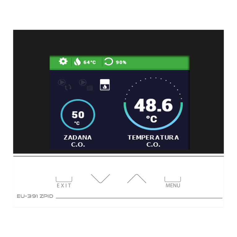
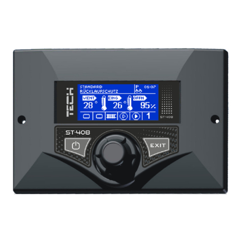
Exemplary view of the main screen:
Any remarks regarding the programme should be reported to the
boiler manufacturer. Each driver should be adjusted according to
individual needs depending on the fuel type used and the boiler type.
TE H shall not be held liable for wrong adjustment of the controller.
I.1. Basic terms
Operation– once activated the controllers enters the operation mode
and a "WORKING" message appears on the display. It is the basic state
of the controller where the blower is operating continuously and the
feeder operation time is set by the user (both operation time and pause
time can be set).
Sustain mode– the mode is entered automatically if the temperature is
higher than or equal to the preset temperature. In such a case the
controller feeds the fuel slowly to reduce the temperature smoothly and a
- 5 -

ST – 480
"SUSTAIN" message appears on the display. Both pause time and
operation time in sustain mode have to be configured for the temperature
to be reduced properly.
II. Functions of the controller
This chapter describes the controller functions, methods of changing
the settings and use of the menu with the pulser (knob). The main
controller screen displays boiler operating parameters. Operation mode
and a number of other settings can be selected by the user according to
the individual needs.
I.2. Main page
Main page is displayed on the graphic display during normal
operation of the controller. Other main screens are displayed according
the operation mode.
Once the pulser knob is pressed the first level menu appears. The
display shows three initial menu options. Further options are available
after turning the knob. An option can be selected by pressing the knob.
Similar procedure is followed when changing the parameters. In order for
the changes to be input they need to be confirmed by pressing the pulser
after the "CONFIRM" message appears. If the user does not intend to
make any changes in a function the pulser should be pressed after the
"CANCEL" message is displayed. Select "EXIT" in the menu or use EXIT
button to exit the menu.
Stand-by mode button located on the controller housing allows
disabling all operating units quickly, if necessary. It serves as an
additional emergency protection to cut-off power supply to all operating
units of the controller (feeder, fan, pumps).
ATTENTION: Power supply to the controller is not cut-off in the stand-by
mode.
I.3. Screen view
The user can select one of three main screens of the temperature
controller operation using that function. They include:
➔central heating screen (displays current boiler operation mode)
valve (displays working parameters of the valve)
➔valve 1 (displays working parameters of the first valve).
- 6 -

ST – 480
➔valve 2 (displays working parameters of the second valve).
NOTE The valve parameter views are available only if the valves have
been properly preinstalled and configured by a technician.
II.1.Preset temperature of the central heating system
The option is used to set the boiler temperature. The user can
change the boiler temperature within the range of 45O to 80O. The
preset central heating system temperature can also be changed directly
in the main screen of the controller by turning the pulser knob.
Additionally, the preset central heating system temperature can be
adjusted using the room temperature reduction function (see Item II.15)
and the weekly control function (see Item II.6). The preset temperature
is a sum of all those values but it may not exceed the range of 45O to
80O.
II.2. Preset temperature of hot domestic water
The option is used to set the temperature of hot domestic water.
The temperature is adjustable within the range between 40° and 75° .
II.3. Manual operation
For your convenience the controller is equipped with a Manual operation
module. When this function is active each actuator (blowing, central heating
pump, hot water pump, additional circulating or valve pump) can be switched
on or off independently and each active mixing valve can be closed, opened or
stopped.
- 7 -

ST – 480
You can start the motor of your selected device by pressing the pulser.
The device will remain activated until the pulser is pressed again.
Additionally, an option to control the blowing power is available where you
can set any fan speed in manual mode.
II.4. Weekly control
The function is used to programme daily changes in the boiler
temperature. The preset temperature deviations are within the range of
+/-100 .
Step #1:
The user needs to set current time and date first (Installer menu >
lock).
Step #2:
The user sets temperature values for individual days of the week (Set
mode 1):
Monday– Sunday
Select specific hours and required deviations from the preset temperature
(how many degrees the temperature should rise or drop) for each day of
the week. Additionally, the preset values can be copied to facilitate the
operation.
Example
Monday
preset: 3 00 , temp. -10° (temperature change– 10° )
preset: 4 00 , temp. -10° (temperature change – 10° )
preset: 5 00 , temp. -10° (temperature change – 10° )
In such a case, if the temperature preset on the boiler is 60º , it will
drop 10º to 50º between 3 a.m. and 6 a.m. on Monday.
- 8 -

ST – 480
As an alternative to the temperatures being preset separately for
individual days, the temperatures can also be set collectively, in the
second mode, for the working days (from Monday to Friday) and the
weekend (Saturday and Sunday) separately - Set mode 2.
Monday - Friday; Saturday - Sunday
Similarly to the previous mode it is necessary to select specific times and
required deviations from the temperature preset for the working days
(Monday - Friday) and the weekend (Saturday, Sunday).
Example
Monday - Friday
preset: 3 00 , temp. -10° (temperature change – 10° )
preset: 4 00 , temp. -10° (temperature change – 10° )
preset: 5 00 , temp. -10° (temperature change – 10° )
Saturday - Sunday
preset: 16 00 , temp. 5° (temperature change +5° )
preset: 17 00 , temp. 5° (temperature change +5° )
preset: 18 00 , temp. 5° (temperature change +5° )
In this case, if the preset boiler temperature is 60º , the temperature
will drop 10º to 50º between 3 a.m. and 6 a.m. on each day from
Monday to Friday. However, the temperature will rise 5º to 65º during
weekend (Saturday, Sunday) between 4 p.m. and 7 p.m.
Step #3:
The user enables one of two preset modes (Mode1, Mode2) or
disables the weekly control option.
Once the mode is enabled the value of the deviation currently set is
displayed on the main page of the controller next to the preset central
heating system temperature. This, additionally, indicates that the weekly
control is active.
Data deletion function is a simple method to remove all previously saved
weekly programme settings to enter new settings.
II.5.Feeding time
This option is used to set the fuel feeder operation time. The time should
be set according to the fuel being used and the boiler type.
II.6. Feeding pause
Feeding pause time is used to set the pause time in feeder operation. The
- 9 -

ST – 480
pause length should be adapted to the fuel type combusted in the boiler. Wrong
selection of operation and/or pause times may result in boiler malfunctioning
i.e. the fuel may be not fully combusted or the boiler may not reach the preset
temperature. Selection of appropriate times will ensure proper operation of the
boiler
II.7. Temperature alarm
The function is activated in the operation mode only (i.e. when the boiler
temperature is lower than the preset temperature). If the temperature is not
rising for a period defined by the user in that function an alarm is activated: the
feeder and the blower are turned off (the pump is turned on and off
independently) and sound is produced. A message reading “Central heating
system temperature is not rising” appears on the display. The alarm is cancelled
by pressing the pulser knob.
II.8. Blowing rate
The function controls the fan operating speed. The adjustment range is
between 1 and 100% (equivalent to fan speeds). The higher the speed is, the
faster the fan operates where 1% stands for the minimum fan speed and 100%
is the maximum speed.
II. . Pump operation modes
This function allows you to select one of the following four boiler operation
modes:
II. .a) House heating
When you select this option the controller switches over to a mode where
heating is provided only to heat the central heating circuit. The central heating
pump begins to run above the pump activation temperature (factory set at 38O
- 10 -

ST – 480
- see Section III.g). The pump will turn off below this temperature (minus a
hysteresis of 2° ).
II.9.b) Boiler tank priority
In this mode, the boiler tank (hot water) pump will be switched on first to run
until the set-point temperature is reached (see Section II.e), after which the
pump will be turned off and the H circulating pump will be enabled.
The central heating pump will run all the time until the boiler tank temperature
drops below its set-point by the hot water hysteresis value. At that moment the
H pump will turn off and the HW pump will turn on (both pumps operating
alternately).
In this mode the fan and the feeder are run only up to 62O as measured at the
boiler (instantaneous set-point) so as to prevent overheating of the boiler.
NOTE: The boiler must be fitted with check valves on the central heating and
hot water pump circuits. The valve mounted on the hot water pump is to
prevent drawing hot water from the boiler tank.
II. .c) Pumps in parallel
In this mode both pumps begin to run together (in parallel) above the pump
activation temperature. However, these temperatures may vary for each pump,
depending on your settings (see Sections III.g-h). When this is so one of the
pumps will switch on earlier than the other one, but after both thresholds are
crossed both pumps will run together. The central heating pump will run all the
time while the hot water pump will turn off when the boiler tank set-point
temperature is reached. It will turn on again when the temperature drops by
the preset HW hysteresis value below its set-point.
- 11 -

ST – 480
II. .d) Summer mode
Once this function is activated the central heating pump will be off and the
DHW pump will turn on above the preset activation temperature (see Section
III.h) and will work continuously until the temperature drops below the
activation temperature by the hot water hysteresis value or until the following
conditions are met:
(boiler temperature) + 2° ≤ (boiler tank temperature)
In summer mode you only enter the set-point temperature of the boiler,
which is also understood to mean the set-point temperature of the boiler
tank.
II.10. Sustained operation
This option is used to set simultaneously the feeder and blower
operating time while the boiler is in the sustain mode.
II.11. Sustain pause
The sustain pause function is used to set the break time in fuel
feeding in the sustain mode. Inappropriate selection of working and
pause times may result in further temperature rise or unintended boiler
shutdown or even lead to conditions where the fuel in the fuel tank gets
fired.
II.12. Fan in sustain mode
The option allows selection of appropriate working and pause times
during the fan operation in sustain mode.
II.15. Room temperature reduction
After the room controller reaches the preset temperature, the preset
boiler temperature (set in the installer menu - see Item III.16) will drop
by the value set there. The reduced temperature will not be lower
however than the minimum preset central heating temperature.
Example: Temperature preset on the boiler: 55º
Room temperature reduction: 15º
Minimum temperature set on the boiler: 45º (factory setting)
Once the preset room temperature is reached (signalled by the room
controller) the temperature preset on the boiler will drop to 45º i.e. only
by 10º although the room temperature reduction is 15º . At the same
- 12 -

ST – 480
time a message reading "!-10º" will be shown in the main display next to
the preset boiler temperature.
II.16 Factory settings
The controller is pre-configured for operation. However, it should be
adapted to individual needs. Factory settings can be restored at any
time. Selection of “factory settings” option will result in all boiler settings
(saved in user’s menu) being lost and reset to boiler manufacturer’s
settings. Individual boiler parameters can be set at that point again.
ATTENTION: Restoration of factory settings will not cause the changes
in service settings to be deleted.
II.17 Information about the programme
This function allows the user to check the controller programme
version.
III. Installation menu
The functions of the installation menu should be set by the person
installing the boiler or service personnel of the manufacturer.+
III.a Main valve
- 13 -

ST – 480
III.a.1 Switch on
This feature allows you to temporarily make the valve inactive.
III.a.2) Set-point valve temperature
This setting is used to set the circuit temperature to be maintained by the
mixing valve. This is the main temperature based on which the room
thermostat reduction function is to be run (see Section III.a.10). The room
thermostat reduction function is set separately for the H system (setting in the
user menu) and separately for each of the valves.
III.a.3) Temperature control
This parameter determines the sampling (control) frequency of the water
temperature downstream of the valve for the central heating or hot water
system. If the sensor indicates a change in temperature (deviation from set-
point), then the solenoid will open or close partially by a preset step to restore
the set-point temperature.
III.a.4) Opening time
You can use this function to set the time for the full opening of the valve,
that is to say, how long it takes to open the valve to 100%. This time should be
selected according to your valve actuator (shown on the nameplate).
- 14 -

ST – 480
III.a.5) Single step
You can use this function to set a percentage value for a single step in the
operation of valve opening, that is to say the maximum percentage value of
opening or closing that the valve can move in a single step (maximum
movement of the valve in one measurement cycle).
III.a.6) Minimum opening
Use this function to set the minimum value for valve opening. Below this
value, the valve will not close shut.
III.a.7) Type of valve
You can use this option to select the type of valve: central heating
or floor type.
III.a.8) Weather program (weekly valve program)
In order to enable the weather function an outdoor sensor should be
installed in a place not exposed directly to sunlight or weather conditions.
After installing and connecting the sensor the Weather program function must
be enabled in the controller menu.
For the valve to work properly enter set-point temperatures (downstream
of the valve) for the following four intermediate outside temperatures:
TEMP. FO -20
TEMP. FO -10
TEMP. FO 0
TEMP. FO 10
Heating curve - curve which is used to determine the set-point temperature of
- 15 -

ST – 480
the controller based on the outside temperature. In our controller this curve is
established based on four temperature set-points selected for their respective
outside temperatures. Set-point temperatures must be provided for the
following outside temperatures: -20º , -10º , 0º and 10º .
The more points there are available for constructing the curve, the greater
is its accuracy, which allows you to determine its shape in a flexible way. In our
case, four points seem to be a very good compromise between accuracy and
ease of setting its shape.
Where in our controller:
XA = -20º , X = 0º ,
XB = -10º , XD = 10º ,
YA, YB, Y , YD – set-point valve temperatures for their corresponding outside
temperatures: XA, XB, X , XD
After weather control is enabled the valve set-point parameter is
calculated based on the heating curve. By changing this parameter you can
decrease or increase all the weather control settings.
III.a. ) Return protection
This feature allows you to enable protection for the boiler from excessively cold
water returning from the main circuit, which could cause the boiler to suffer
from low-temperature corrosion. The return protection function works to ensure
that when the temperature is too low the valve will close partially until the short
circuit of the boiler reaches the desired temperature. This feature also protects
the boiler from a dangerously high return temperature to prevent water from
boiling.
When this function is enabled you need to set the minimum and maximum
return temperatures.
III.a.10) Room thermostat reduction
This function is active only when the unit is operated with a (standard or
- 16 -

ST – 480
TE H) room thermostat. When the room thermostat reaches the desired
temperature in the house/flat (reports heated up condition), the valve will close
to such an extent so that the temperature downstream of the valve drops by
the <room thermostat reduction> temperature.
NOTE: If the installation includes a TECH room thermostat with S
communication (four-wire cable), you may choose an option providing dynamic
control for the mixing valve (see Section III.a.11)
III.a.11) Operation of TECH thermostat
This setting is active only if the controller is connected with a TE H room
thermostat (with RS communication) and allows a choice in how the thermostat
is to work together with the mixing valve:
temperature reduction – when you select this mode after heating up
the house/flat to your required temperature set-point temperature the TE H
room thermostat will lower the set-point temperature of the valve by the pre-
set room thermostat reduction value (see Section II.a.10);
dynamic changes - when you select this mode after heating up the
house/flat to the set-point temperature the TE H room thermostat will work as
per the following settings:
Change in valve set-point. This setting determines by how many
degrees the valve temperature is to increase or decrease with a single unit
change in room temperature. This function is closely related to the oom
temperature difference parameter.
oom temperature difference. This setting is used to define the single
unit change in the current room temperature (accurate to 0.1° ) at which there
is to occur a specific change in the set-point temperature of the valve.
Example:
setting: oom temperature difference 0.5ºC
setting: Change in set-point valve temperature 1ºC
setting: Set-point valve temperature 40ºC
setting: Set-point room thermostat temperature 23ºC
Case 1. If the room temperature rises to 23.5º (by 0.5º ) the valve will close
to such an extent as to have 39º as a set-point (by 1º ).
Case 2. If the room temperature drops to 22º (by 1º ) the valve will open to
such an extent as to have 42º as a set-point (by 2º ).
- 17 -

ST – 480
III.a.12) Factory settings
This parameter allows you to restore the mixing valve settings saved by
the manufacturer. By restoring the factory settings you will not change the
valve type setting (central heating or floor type).
III.b) Valve 1
NOTE: ontrol with an additional valve (1 or 2) is only possible after you
purchase and connect the controller to an additional control module (ST-61),
which is not provided as standard equipment with the controller. In order to
control two valves you need to connect two ST-61 modules.
The options presented in this chapter are used to adjust the operating
settings of an additional mixing valve. In order for the valve to work properly
and meet your expectations it should be configured with its parameters set like
in the case of the main valve.
- 18 -

ST – 480
III.b.1)Registration.
To register an additional valve enter the serial number of the control module of
the ST-61 mixing valve servo (look for the five-digit number on the cover of
this module). Without this number the valve cannot be activated.
III.b.2) Switch on (setting as for the main valve - see Section
III.a.1).
III.b.3) Set-point valve temperature (setting as for the main valve
– see Section III.a.2)
III.b.4)Room thermostat
If the valve is to be operated with a room thermostat, you should
select its type:
module controller (traditional two-state type – “from the module”),
standard or TE H controller (traditional two-state type – “from the
controller”),
TE H algorithm controller (RS communication),
room temperature difference (setting as for the main valve – see
Section III.a.11),
set-point change (setting as for the main valve – see Section III.a.11).
III.b.5) Temperature control (Setting as for the main valve – see
Section III.a.3).
III.b.6) Opening time (Setting as for the main valve – see Section
III.a.4)
III.b.7) Single step (Setting as for the main valve – see Section III.a.5).
III.b.8) Minimum opening (Setting as for the main valve – see Section
III.a.6).
III.b. ) Type of valve (Setting as for the main valve – see Section
- 19 -

ST – 480
III.a.7).
III.b.10) Weather program (weather control) (Setting as for the
main valve – see Section III.a.8).
III.b.11) Return protection - (Setting as for the main valve – see
Section III.a.9).
III.b.12) Additional sensors
When two mixing valves are used and you select this function you will be
able to select the sensors from which temperature data are to be retrieved for a
valve (for return and outside temperature sensors). Temperatures can be
retrieved from the sensors of the valve being set (Own) or as per the controller
sensors (Main controller).
III.b.13) Room thermostat reduction (Setting as for the main
valve – see Section III.a.10).
III.b.14) External sensor adjustment
The external sensor is to be adjusted during installation or after prolonged
use of the thermostat if the outside temperature displayed deviates from the
actual one. Adjustment range: -10 to +10 O with an accuracy of 1O
III.b.15) Factory settings (Settings as for the main valve – see Section
III.a.12)
III.b.16) Valve removal
This function is used to completely remove a valve from the controller
memory. Valve removal is used for example when removing or replacing a
module (the new module requires to be registered again).
- 20 -
Table of contents
Other TECH Controllers manuals
