Sonic Nuance Electronics TDI User manual

Page 1 © 2012-2020 Sonic Nuance Electronics
Hear Everything, Always
TDI User Manual v3.0
January 2020
Introduction
Hello,
My name is Ted and I have designed, assembled, tested and hand signed your TDI
(tuner + DI). I thank you for your purchase and welcome you to the Sonic Nuance
Electronics family - people like you who crave to hear every thing, always!
The TDI integrates a chromatic tuner with a DI and transparent 1/4” bu!er. It has a
quiet mute feature as well as 48V XLR or DC-jack powering and super bright LEDs.
Audiophile-grade quality components are used (including costly wide dynamic range, low
noise op amps, low distortion mechanical relays, "lm capacitors and tightly matched
resistors) for the all analog signal path to provide uncompromising sound quality over a
wide dynamic range for years to come.
While the TDI is simple to use, reading this manual will help you get the most out of it
and help answer common questions. However, don't hesitate to contact me should you have
any questions or suggestions at sonicnuance.com.
History
I started Sonic Nuance Electronics in 2012 with the original TDI, thus it has a special place
in my heart.
After years of playing live gigs as an amateur bassist and acoustic guitarist, my dream was
to minimize the gear I needed to bring while still having pristine and reliable sound. The idea
was to combine the only pieces of equipment I consistently needed (a tuner, a DI and a patch
cable connecting them), and removing the need for a separate power source like a battery or
DC adapter. Being part of a portable church’s worship team that set up and tore down
equipment multiple times a week, I learned quickly what was needed as well as what lasted
and what didn’t. I have been using the TDI to this day, usually in a minimalist setup as shown
in Figure 1. Soundmen love it for the sound, simplicity and no need for a battery. Stage and
lighting designers love it because it is so small.
I do
Figure 1: Minimalist setup with mixing board powering
the TDI.
Page 2 © 2012-2020 Sonic Nuance Electronics
Front Panel
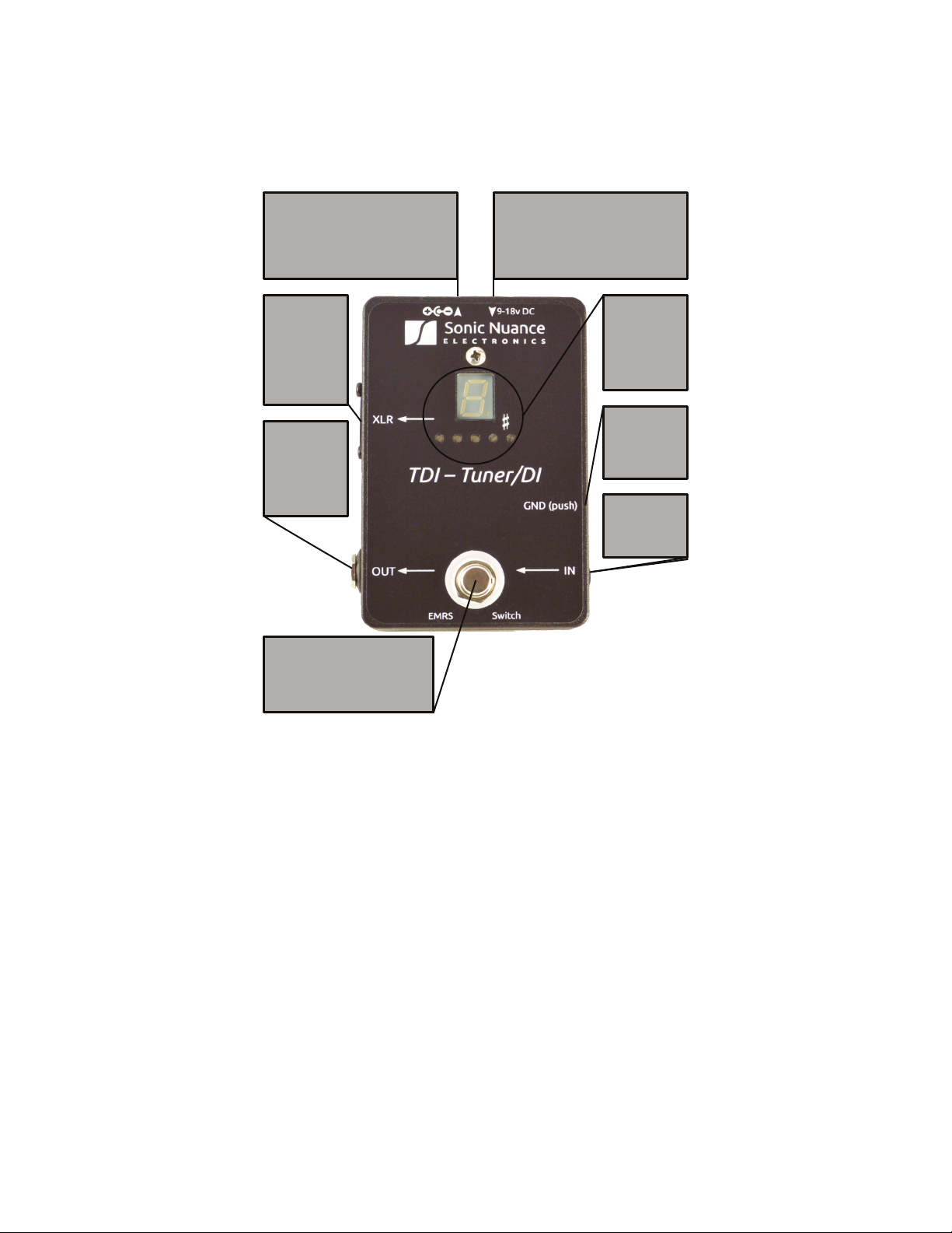
Figure 2 shows the TDI’s front panel, please take a moment to familiarize yourself with it.
XLR jack
This balanced
output allows the
TDI to be powered
by 48V phantom
power with a true
ground lift!
Phantom power
overrides DC IN
and does not
provide DC OUT.
OUT jack
Provides a
bu!ered output
of IN unless in
tuning mode
where it mutes.
Like the XLR
output this can
drive long lines.
LED display
Indicates mode of
operation ("P" is
play), tuning note
and accuracy level
(left is "at, right is
sharp, "ashing
motion is tune
properly).
IN jack
This unbalanced
high impedance
input accepts all
pickup types
including piezo.
Foot switch
This puts the TDI in TUNING mode
(which mutes OUT & XLR) or PLAY
mode. The switching scheme uses
EMRS (electro-mechanical relay soft)
switching for the ultimate in
reliability and sonic performance.
Ground button
Pressing this
button in ties pin1
of the XLR to the
TDI's ground.
Depressing lifts
the ground
DC OUT jack
This standard, center negative 2.1mm jack
is a copy of the input supply on DC IN jack
and provides an auxiliary output to free up
power supply outputs on "brick" power
supply units. Make sure total power
consumption doesn’t surpass power
supply’s rated output.
DC IN jack
Connect a standard, center negative
2.1mm terminal from an AC adapter. The
supply should be regulated and provide at
least 10mA. Voltage should be 9-18V.
Higher voltage gives more headroom.
Both DC jacks are polarity protected. Do
not exceed18V on DC IN.
Additional Notes on Front Panel
DC IN Jack: This jack is polarity and over-voltage protected. Use a center negative dc supply
(not included) with 9 to 18V voltage (18V is preferred as it gives additional headroom to
the signal path which further reduces unwanted distortion). The TDI uses very little current
(less than 10mA) so a standard 100mA power source will be plenty. If the TDI is XLR
powered, this jack does not function.
DC OUT Jack: This output is polarity protected so if you accidentally were to plug a power
supply here it won't damage the SBS under normal circumstances. This will be a copy of the
voltage provided on the DC IN jack. Make sure the power supply tied to DC IN has a current
capacity high enough to drive the TDI plus whatever is tied to DC OUT (maximum 300mA
out of DC OUT which is fuse protected).
IN Jack: If no input is provided, both 1/4" OUT and XLR are automatically muted. The input
impedance is typically 2Meg ohms.
XLR Jack: If powering the TDI via phantom power, make sure to provide 48V (P48) on this
jack. Lower voltages will not be able to power the unit consistently. The DC in and DC out
jacks are automatically disabled when XLR powering. Make sure to mute the channel the
XLR will be plugged into as the sudden current drain on the line will cause a loud "pop" just
Figure 2: TDI Front Panel

Page 3 © 2012-2020 Sonic Nuance Electronics
Additional Notes on Front Panel (Continued)
Foot switch: This will respond to toggling about once every three seconds. Faster toggle
rates will be !ltered out and ignored.
GND (push) switch: Unlike other products, the TDI uses a patented design allowing it to be
powered via the XLR jack even when the ground is lifted.
OUT jack: This is a bu"ered and transformer isolated copy of the signal on the IN Jack. It is
designed to provide superior performance to so called "true bypass" designs. This can drive
200 feet of cable with ease, and with transformer isolation, it helps remove the hum caused
by ground loops.
Powering the Unit
To avoid the transient audio "pop" when powering up or down the TDI, follow this rule:
make sure that what the TDI's XLR and 1/4" OUT jacks are connected to are muted or o! "rst.
For example, before powering on or o"the TDI when connected to the input of an
ampli!er, make sure the amp is muted or o" !rst. This way the turn on or o"transient
"pop" of the TDI (or any other equipment it is connected to for that matter) will be muted.
Similarly, if the TDI is to be powered via the XLR plug, make sure the channel the XLR is
connected to on the mixer is muted before connecting/disconnecting the XLR plug.
After powering up the TDI, it is recommended to wait 2-3 minutes before using the foot
switch. Due to the high input impedance of the bu"ers, it takes some time to allow internal
voltages to stabilize and make the switching as audibly quiet as possible.
Modes of Operation
The TDI can be in one of two modes: TUNING and PLAY modes. In TUNING mode, the
display shows the current note detected on the input jack (or C” if nothing is detected as
the tuning algorithm is cleared when !rst put in this mode or on power up. Once a note is
detected, the display will change accordingly and remain until another note is detected or
the mode is changed). Upon power up, the TDI will start in tuning mode for most situations.
In PLAY mode, the display indicates the letter P. The internal digital clock is slowed to a
minimum to avoid digital "hash" corrupting the analog signal. Getting rid of this hash is
especially important when using high gain ampli!ers. Also, unlike the competition, the
signal does not pass through a transistor switch which can cause unwanted distortion.
Tuning with the TDI
To engage the tuner, make sure the display does NOT show the letter P. When the tuner is
activated, both XLR and 1/4" OUT outputs are muted for silent tuning. (Note that this
could also be used to change instruments without bothering the soundman in live
situations.)
Pluck a single note at a time (you should mute the strings not being tuned) and the display
window will indicate the note that is being played. A dot in the lower right corner of the
display indicates the sharp (#) of the note. The display indicates the chromatic notes
detected in "mute mode" as shown in the table below:
Note A A# B C C# D D# E F F# G G#
Display AA.BCC.DD.EFF.GG.
Page 4 © 2012-2020 Sonic Nuance Electronics
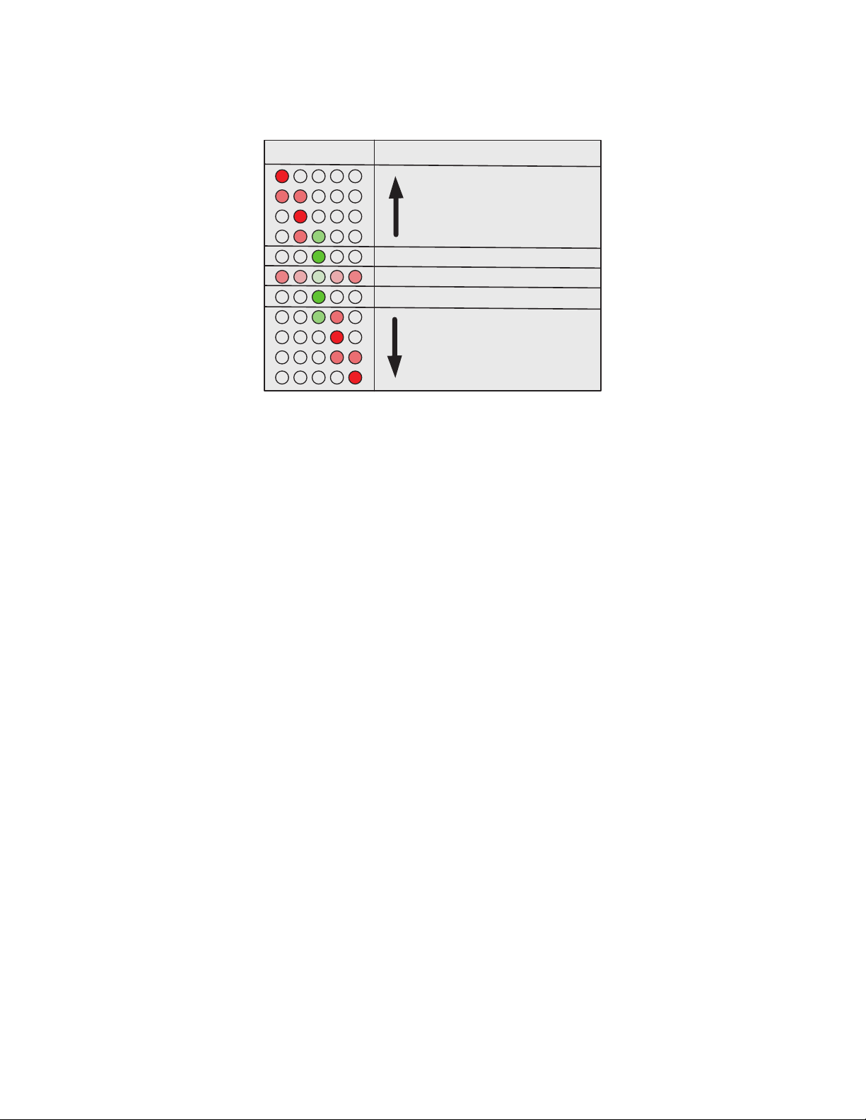
Tune your string up or down until the center "in tune" LED is displayed or a sequence of
outer LEDs go toward it in a !ashing pattern indicating proper tuning stability is achieved.
Figure 3 shows the mapping between the LED tuning accuracy display and the level of
tuning.
The TDI's chromatic tuner is quite sensitive (at least +/- 1 cent) and has a large dynamic
range. You may "nd that plucking a string lightly with the volume knob at maximum gives
faster and/or more stable note detection. This is due to the fact that most instrument
strings pull sharp by up to 10 cents depending on how hard they are plucked and introduce
more overtones. Rather than completely eliminating this information, the TDI shows some
of it allowing the user to see the e#ect of attack and overtones on pitch. The harder the
string is plucked, the more sharp the initial attack will be and the more overtones there will
be. For this reason, either plucking the string lightly or waiting for the string amplitude to
decay may give more stable results.
If tuning is still di$cult, try one or more of the following:
1) tune using the 12th fret harmonic on a guitar/bass
2) pluck closer to the neck or use the tone knob to get fewer overtones
3) use the neck pickup vs the bridge pickup on multi pickup instruments to get fewer
overtones
4) tune going from !at to sharp while slowly turning the instrument's tuning machine
5) dampen all strings but the one you are focusing on
6) tune an acoustic-electric instrument when the soundboard isn't vibrating due to other
band instruments playing (i.e. drums, loud bass, etc)
Due to the accuracy of the TDI, you may also notice the following:
1) tuning while sitting with your instrument gives a di#erent result than when standing
(since the torque on the neck is slightly di#erent between sitting and standing).
2) as a note decays it may not stay at the same tuning level. This depends on many factors
regarding stability of the instrument's saddles, neck and body.
Figure 3: Accuracy Display
Note Progressively Flatter
Note Progressively Sharper
Note in tune
Note in tune
Flashing indicates tuning is stable
Accuracy Display Description

Page 5 © 2012-2020 Sonic Nuance Electronics
Usage Models
The TDI can be used in a variety of settings. This section shows some of them.
Figure 4: Piezo equipped banjo direct into the TDI.
Mixing board powering the TDI via 48V on XLR cable.
Figure 5: TDI Powered via 48V on XLR cable
simultaneously driving an amp. Outputs are ground
isolated.

Page 6 © 2012-2020 Sonic Nuance Electronics
amp send
Figure 6: TDI used in ampli!er's e"ects loop while
powered with DC adapter. XLR signal has ampli!er's
tone while being ground isolated. Both amp and XLR
are muted during tuning.
amp return
Page 7 © 2012-2020 Sonic Nuance Electronics
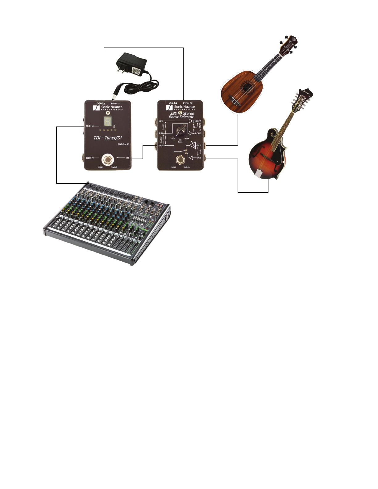
Figure 7: TDI DC powered and provides power
to a Sonic Nuance SBS stereo boost select
pedal. SBS has the same bu!er technology as
the TDI and can be driven by piezo pickups.
XLR gets either mandolin or ukulele signal
depending on SBS setting.
Additional Design Information
I spent a lot of time designing the signal path to make it as low noise, and transparent as possible
as I didn't want the TDI to color the signal in any way. In doing so I changed from a typical “hard"
mode switching scheme using latching foot switches which wear out to using electro mechanical
relays with foot switch actuators and “soft" switching. This was more expensive but more reliable and
consistently quiet during switching. The circuit uses a combination of high reliability and noise
immune discrete digital circuits combined with low signal mechanical relays with over 10 million cycle
lifetimes. The foot switch actuator used in the design translates up to 500 pounds to about 100
grams of force on the internal circuit board. This virtually eliminates wear and tear to the TDI's
internal circuits due to switching. I call this switching scheme EMRS (electro mechanical relay soft)
switching. I don't claim to have invented this approach, I just couldn't "nd an easier way to describe
it.
I also maximized the range of the XLR-derived power supply to allow the high end op amps to
maximize their dynamic range and minimize distortion. The circuit is able to be powered via a DC
adapter from 9V to 18V for extra headroom. Because the input impedance is quite high, piezo
pickups can drive the TDI directly. I also added a DC output so that this “accessory” pedal doesn’t use
up a precious DC power line on e!ects boards.
Finally, I ask that you not tighten any of the screws unless they are obviously loose. Thread
locking compound was used in many cases and over tightening could damage the unit. -Ted
Page 8 © 2012-2020 Sonic Nuance Electronics
Frequency Response (+/-0.5dB) 20~20kHz
Input Impedance 2Meg ohms
Output Impedance XLR & 1/4” 200 ohms
Maximum Input 10dBu @ 1kHz
XLR Output Bu!ered impedance balanced, low noise, high
slew rate, high dynamic range
1/4” Out Bu!ered, transformer isolated, low noise, high
slew rate, high dynamic range
Tuning Range E0-E5 (~20Hz to ~660Hz) (below low B of bass to
12th fret high E string of a standard tuned
guitar)
Tuner Accuracy +/- 1 cent minimum
Power Requirements XLR: 48V (P48) IN: 9-18V 100mA min
Maximum DC out current Limited by the smaller of the DC IN’s supply or
300mA
Mechanical Relay Lifetime 10,000,000 cycles min
Warranty Three years limited. See website for details
Speci!cations (Typical Values Unless Stated Otherwise)
California Proposition 65 Requirement
To meet the requirements of California Proposition 65, it is our responsibility to inform you
of the following: WARNING: This product contains chemicals known to the State of
California to cause cancer, birth defects or other reproductive harm. Please take proper
care when handling and consult local government regulations before discarding.
EMC Notice
This equipment has been tested and found to comply with the limits for a Class B digital device,
pursuant to part 15 of the FCC Rules. These limits are designed to provide reasonable protection
against harmful interference in a residential installation. This equipment generates, uses and can
radiate radio frequency energy and, if not installed and used in accordance with the instructions,
may cause harmful interference to radio communications. However, there is no guarantee that
interference will not occur in a particular installation. If this equipment does cause harmful
interference to radio or television reception, which can be determined by turning the equipment o!
and on, the user is encouraged to try to correct the interference by one or more of the following
measures:
— Reorient or relocate the receiving antenna.
— Increase the separation between the equipment and receiver.
— Connect the equipment into an outlet on a circuit di!erent from that to which the
receiver is connected.
— Consult the dealer or an experienced radio/TV technician for help.
Hear Everything, Always
www.sonicnuance.com
Table of contents


