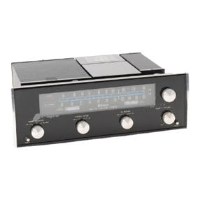
McIntosh MR66 User manual

STEREO
TUNER
MR66
TABLEOFCONTENTS
INTRODUCTION
TECHNICALDESCRIPTION
FRONTPANELINFORMATION
BACKPANELINFORMATION
INSTALLATION
CONNECTING
MonophonicFMandAM
StereophonicFMandAM
StereophonicFMMultiplex
RemoteAmplifiers
Off-The-AirTapeRecording
AntennaConnections
OPERATINGINSTRUCTIONS
MonophonicAMReception
MonophonicFMReception
StereophonicFM-AMReception
StereophonicFMMultiplexReception
ADJUSTMENTS
MutingThreshold
AMSignalStrengthIndicator
FMTuningMeter
AMandFMOutputLevels
DialPanelLight
GUARANTEE
1
1
3
5
6
8
8
9
9
9
9
9
11
11
11
12
12
12
12
12
13
13
14
14
MR66


MR66STEREOPHONICTUNER
INTRODUCTION
TheMclntoshMR66isa precisionengi-
neered,sensitiveAM-FMstereotuner.It
offersthefinestpossiblereceptionofAMand
FMbroadcasts.Everydesirablefeatureis
includedontheMR66.Itisperfectforusein
astereosystemwherenothinglessthan
THEBESTwilldo.
OnceyouhaveusedtheMR66anden-
joyeditsoutstandingperformance,youwill
understandwhyMclntoshproductshave
earnedtheirreputationasTHEBEST.
TheMR66isquiteflexibleinoperation.It
receivesmonophonicFM,monophonicAM
andstereophonicAM-FMbroadcasts.Italso
receivesFMmultiplexstereophonicbroad-
castswiththesimpleadditionoftheMcln-
toshMA6multiplexadapter.TheMR66front
panelcontrolandswitchfacilitiesprovidefor
everydesirablemodeoftuneroperation.
YourMclntoshMR66tunerwillgiveyou
yearsofthefinestpossibleAMandFM
receptionandwillbecomea highlyvalued
partofyourhomemusicsystem.
TECHNICALDESCRIPTION
FMSECTION
TheMR66FMRFtuningsectionusesa
specialcascodeamplifierthatamplifiesthe
weakestsignalsandyetmaintainslownoise
andfreedomfromspurioussignals.An
additionaltunedRFcircuitcombinedwitha
4gangtuningcapacitorcontributesgreatlyto
theexcellentselectivityandhighrejectionof
spurioussignals.
AnewlydevelopedAutomaticFrequency
Control(AFC)circuitgreatlysimplifiestuning.
Asthetuningknobismoved,thetunerre-
spondsasiftherewerenoAFCaction.
Approximately3 secondsafterthedialhas
cometorestona particularstation,theAFC
circuitgraduallycomesintooperation.The
AFCactionautomaticallybringstheelectrical
tuningtothecorrectpointforminimumdis-
tortion.Thisautomatictuningrepeatsits
actioneachtimethetuningdialismovedtoa
differentstation.TheamountofAFCaction
isfullyadjustable witha frontpanelcontrol.
TheuniqueAFCcircuitusesa variable-
capacitancesilicondiodeinplaceofa con-
ventionaltubetoimprovetheover-allAFC
performance.Thesilicondiodeisunaffected
bytemperaturechanges,hasnowarmup
drift,andeliminatestubefilamenthum.A
specialtemperature-compensatednarrow-
banddetectorsuppliesoperatingsignalsto
theAFCcircuittoinsurepositiveaction.
Thenarrow-banddetectoralsooperatesthe
FMtuningmeteramplifierandtheultrasonic
interstationmutingcircuit.
Threeflat-toppedresponseIFamplifiers
rejectadjacentchannelinterferenceand
provideadequategaintooperateboth
limitersoneventheweakestsignals.Two
limitersareusedtoinsurethebestpossible
signal-to-noiseratio.BoththeRFandIF
circuitsarecompletelyshieldedandexceed
theFCCrequirementsforsuppressionof
FMoscillatorandIFfrequencyradiation.
1

AMSECTION
TheMR66deliversAMreceptionofthe
highestpossiblequality.FourdifferentAM
bandwidth/frequencyresponsesettingsare
available.TheNARROWsettingprovides
excellentselectivityandhighnoiserejection
fortheweakerandmoredistantstations.
TheMEDIUM1,MEDIUM2 andBROAD
settingsprovideprogressivelywiderfre-
quencyresponseforreceivingthecloser
morepowerfulstations.
InallbuttheBROADsettinga verysharply-
tunedwhistlefiltereliminatesthe10KC
interferencecausedbyadjacent-channelsta-
tioncarriers.Thishighly-selectivefilterre-
ducesthe10KCinterference60db(decibels)
belownormalprogramlevelwithnoeffecton
otheraudiofrequencies.
LocalAMreceptionattheBROADand
MEDIUM2 settingsisofunusuallyhigh
fidelityandlimitedonlybythequalityofthe
actualbroadcastsignalitself.
Adouble-tunedcircuitattheinputofthe
RFamplifierincreasesselectivitywhilere-
tainingtheexcellentAMbandwidth.The
antennacoilsareconnectedwitha rear
panelswitchtoallowperfectmatchingofa
convenientshortloopantennaora conven-
tionallongleadantenna.
AnamplifiedautomaticVOLUMEcontrol
circuitmaintainsuniformvolumeoutputover
awiderangeofstationsignalstrengths.
Powerfullocalstations,aswellasweakor
distantstations,arereproducedatanalmost
equalvolumelevel.Theneedforconstant
volumeadjustmentduringtuningisthere-
foreeliminated.
TwoIFamplifiersarecoupledthrougha
low-distortiondetectorintoa two-stagefeed-
backamplifier.Theoutputislow-impedance
andapproximatelyequalinleveltotheFM
output.Levelcontrolsontherearpanelallow
youtoexactlymatchtheAMandFMoutput
volumelevels.
GENERAL
Anewtypeofmechanicaltuningassembly
givestheMR66extremelysmoothflywheel
tuning.Thetuningcapacitorsaredriven
directly;thetuningcapacitors,inturn,drive
thedialpointers.Backlashispractically
eliminatedwiththismethodofdesign.
Ateflon-linedpointercarriageandnylon
pulleysreducefrictionandweartogivean
unusuallysmoothandquietdialaction.
SPECIFICATIONS
FMCHANNEL
Sensitivity
3¼microvoltsat100%modulation(±75KC
deviation)forlessthan3%totalnoiseand
distortioninaccordancewithIHFMstandards.
Distortion
Lessthan0.8%at100%modulation(±75KC
deviation),above10microvoltsatantenna
terminals.
AudioFrequencyResponse
Within2dbfrom20to20,000cycles.
CaptureRatio
1to0.7
Muting
IFinjectedultrasonicmuting;60dbormore
noisereductionbetweenstations.
OscillatorDrift
Lessthan25KCwithAFCdisabled;negligible
withAFCinoperation.
ImageRejection
Betterthan80dbat90MC;betterthan
70dbat105MC.
Hum
Betterthan65dbbelow100%modulation.
IFAmplifiers
Three(notincludingtwolimiters)with200KC
bandwidth,flat-topresponse.
RFAmplifier
Cascode
Radiation
SubstantiallybelowFCCrequirements.
AntennaInputs
300ohmsbalanced;75ohmsunbalanced.
Output
Approximately4 volts,lowimpedance.
2

AMCHANNEL
Sensitivity
1.5microvolts.
Selectivity
Narrow;4KCbandwidth,± 10KCfromcenter
down53db.
Medium1;13KCbandwidth,±10KCfrom
centerdown20db.
Medium2;23KCbandwidth,±10KCfrom
centerdown1.5db.
Broad;23KCbandwidth,± 10KCfromcenter
down1.5db.
Thesecharacteristicsaresubstantiallyun-
changedoverentireRFtuningrange.
Distortion
Lessthan1½%at100%modulation.
Hum
50dbbelowfullsignal.
AudioBandwidth
Narrow;within3db,20to2,000cycles.
Medium1;within3db,20to6,500cycles.
Medium2;within3db,20to8,000cycles.
Broad;within3db,20to11,500cycles.
10KCWhistleFilter
70dbrejectionat10KC;noneonBroad
setting.
Output
Approximately4 volts,lowimpedance,
PowerConsumption
75watts,105to125volts,50to60cycles,
(entiretuner).
TubeComplement(18)
6BA6AMRFAmplifier
6BE6AMConverter
6BA61stAMIFAmplifier
6BY82ndAMIFAmplifier
6BY8AGCAmplifier
6U8AMAudioPreamplifier
6BN4AFMRFAmplifier
6BN4AFMOscillator
12AT7FMMixer
(3)6AU6FMIFAmplifiers
6BN8FMUltrasonicMuting
6AU61stFMLimiter
6CS62ndFMLimiter
12AU7FMMeterandAGCClamp
6U8FMAudioPreamplifier
6BW4HighVoltageRectifier
(10mmutobothchannels)
Dimensions
FrontPanel:155/8inchesby51/8inches.
Overalldepthofchassisbehindfrontpanel:
123/16inches.
Depthfromfaceofknobstofaceofmount-
ingpanel:1¼inches.
Weight
Chassis-only,27pounds;inshippingcarton,
32pounds.
FRONTPANELINFORMATION
TUNINGDIALS
TheMR66includesAMandFMtuning
dialsonthefrontpanel.TheAMtuningknob
isattheleftandtheFMtuningknobisatthe
right.TheAMtuningdialiscalibratedin
kilocyclesandtheFMtuningdialiscalibrated
Figure1.MR66FrontPanel.
inmegacycles.Eachtuningdialalsoincludes
a0-100loggingscale.Tuningbacktoa
particularstationismucheasierbykeeping
arecordoftheexactstationlocationonthe
loggingscale.3

TUNINGMETERS
Twotuningmetersareincludedinthedial
panel.AttheleftistheAMSIGNALSTRENGTH
tuningmeter.AttherightistheFMTUNING
meter.
AnAMstationiscorrectlytunedwhenthe
AMsignalstrengthmeterpointerindicates
maximumright-handdeflection.Theactual
amountofmeterpointerdeflectionindicates
therelativesignalstrengthofeachparticular
station.Stronglocalstationswillcause
almostfullmeterdeflection.Weakerormore
distantstationsmaycauseonlya slight
meterdeflection.
AnFMstationiscorrectlytunedwhenthe
pointeroftheFMtuningmetercomestorest
anywhereinthesmallblackcenterareaof
themeterscale.
Thezerosettingsofbothmeterscanbe
adjustedifnecessary.Seethesectiontitled
"ADJUSTMENTS."
AMFUNCTIONSWITCH
MultiplexFM
ProvidesmultiplexFMstereoreceptionwith
thesimpleadditionofa MclntoshMA6
multiplexFMadapter.
AMOut
TurnsofftheAMsectionoftheMR66.
Narrow
SharpestandmostselectiveAMtuningfor
receivingdistantorweakstationswith
minimumnoiseandinterferencefromother
stations.
Medium1 andMedium2
Progressivelywiderfrequencyresponsefor
closerormorepowerfullocalstations.
Broad
WidestpossibleAMfrequencyresponsefor
high-fideiityreceptionofpowerfullocalsta-
tions.The10KCwhistlefilterisnotoperative
atthisswitchsetting.
MODESELECTORSWITCH
Figure3.ModeSelectorSwitch.
PowerOff
TurnsofftheMR66ACpower.TheACoutlet
onthebackpanelalsoturnsoffwiththis
switch.Ifa TVantennaisusedforFMinthe
mannerdescribedunder"ANTENNACON-
NECTIONS,"itwillautomatically beswitched
backtotheTVsetinthePOWEROFFposition.
Stereo
TurnstheMR66ACpowerONandprovides
simultaneousAMandFMsignalsattheback
paneljacksmarkedSTEREO-MON1 and2,
respectively.
MONFM
ProvidesmonophonicFMsignalsat"both"
theSTEREO-MON1 and2 backpaneljacks.
MONAM
ProvidesmonophonicAMsignalsat"both"
theSTEREO-MON1 and2 backpaneljacks.
Note:
AMsignalsarealwayspresentattheback
pane!AMjack,andFMsignalsarealways
presentattheFMjack,regardlessofthe
MODESELECTORswitchsettings.
AUTOFREQCONTROL
Theautomaticfrequencycontrol(AFC)
circuitmakesFMtuningeasierandelimi-
4
Figure2.AMFunctionSwitch.

natesthepossibilityofthetunerdriftingoff
thestation.TheAFCcircuitintheMR66in-
cludesanElectronicDelaywhichisanexclu-
siveMclntoshdevelopment.Asthetuning
dialismoved,theAFCcircuitistemporarily
cutoff.Approximatelythreesecondsafter
thedialpointerhascometorestona particu-
larstation,theAFCactiongraduallycomes
intooperation.TheAFCautomaticallybrings
theelectricaltuningtothecorrectpointfor
minimumdistortion.Thisautomatictuning
repeatsitselfeachtimetheFMdialismoved
toa differentstation.
ThedegreeofAFCactionisadjustable
withtheAUTOFREQCONTROL.Fullleft
(MIN)positionofthecontrolcutsoffAFC
action.Fullright(MAX)positiongivesmaxi-
mumAFCaction.
Normally,thebesttuningoccurswiththe
AUTOFREQCONTROLsetatornearMAX
position.Ifseveralstationsareveryclose
togetheronthedialorifa desiredstationis
closetoa muchstrongerstation,a lower
AFCsettingisusuallynecessaryforbest
tuning.
FMFUNCTIONSWITCH
FMOut
TurnsofftheFMsectionoftheMR66.
MuteIn
TurnsonFMwiththeMclntoshdeveloped
ultrasonicmute-inoperation.Ultrasonicmut-
ingsuppressesallnoisebetweenstations
includingnoisesheardtuninginandoutofa
station.Weakordistantstationsmixedwith
noiseorinterferencearealsosuppressed.
MuteOut
Turnsofftheultrasonicmutingtoallowcon-
ventionalFMtuningwithinter-stationnoise
present.Usethissettingtolistentoweakor
distantstationsthatmaybemixedwithnoise
orinterference.
BACKPANELINFORMATION
Figure6-MR66BackPanel.
FMMULTIPLEXOUTPUT
ConnectstotheinputleadoftheMclntosh
MA6FMmultiplexadapter.
FMMULTIPLEXPOWER
ConnectstotheMclntoshMA6FMmulti-
plexadapterpowerplug.Correctoperating
voltagesaresuppliedfortheMA6(6.3volts
ACat1 ampand120voltsDCat25ma.)
MULTIPLEXINPUTS
ConnecttotheMclntoshMA6FMmulti-
plexadapteroutputleads.
AMANTENNA
TerminalsforconnectingtheAMantenna
totheMR66.
Figure4.AutoFreqControl.
5
Figure5.FMFunctionSwitch.

ANTLOOPSWITCH
AdjuststheMR66circuittomatchthe
particulartypeofAMantennaused.ANT
positionisfora conventionalantenna,
usuallyoftheoutdoortype,from50to150
feetinlength.LOOPpositionisfortheshort
loopantennasuppliedwiththeMR66.
LAMPSSWITCH
Providesbright(HI)ordim(LO)front
panellighting.
ACOUTLET
Provides117voltACpowerupto350
wattsmaximumforadditionalequipment
suchasturntablesorothertuners.Thisout-
letisnotfusedandturnsonandoffwiththe
frontpanelMODESELECTORswitch.
FUSE
1ampSlo-Blotypefusetoprotectthe
tunercircuit.Thisfusedoesnotoperateon
theACoutlet.
FMANT
TerminalsforconnectinganFMantenna
totheMR66.
TOTVSET
TerminalsforconnectingTVsetantenna
leadswhena VHFTVantennaisusedfor
boththeMR66andtheTVset.Theantenna
isautomaticallyswitchedtotheMR66when
theMODESELECTORturnstheMR66ON.
TheantennaisswitchedbacktotheTVset
whentheMODESELECTORisturnedto
POWEROFF.
STEREO-MONOUTPUTS
1and2 outputjackssupplytunersignals
ofthecorrectvaluetoconnecttotunerinputs
orauxiliaryinputsofa controlpreamplifier.
ThefrontpanelMODESELECTORswitchpro-
videsstereoAM-FMatjacks1 and2,re-
spectively;monophonicFMat"both"jacks
1and2;ormonophonicAMat"both"jacks
1and2.
AMFMOUTPUTS
AMsignalsarepresentattheAMjackand
FMsignalsarepresentattheFMjackatall
timesthetunerisoperating,regardlessof
theMODESELECTORswitchsetting.The
AMfunctionswitchandtheFMfunction
switchaffectthesignalsattheseoutput
jacks.Usethesejackstoconnectthetuner
toremoteamplifiers,apartfromthemain
soundsystem.
AMOUTPUTLEVELCONTROL
AdjuststhevolumeleveloftheAMoutput.
Seesectiontitled"ADJUSTMENTS."
FMOUTPUTLEVELCONTROL
AdjuststhevolumeleveloftheFMout-
put. Seesectiontitled"ADJUSTMENTS."
INSTALLATION
TheMclntoshMR66tunermaybein-
stalledona table,ona shelf,ina custom
built-incabinetorina professionalequip-
mentrack.Forbestappearanceinanopen
installation,itissuggestedthatyoumount
theMR66intheattractiveMclntoshModel
L66finishedwoodcabinet.
TheMR66maybemountedinpanelsup
to1 inchinthickness.Ifthepanelisatleast
¼inchinthickness,thetunerwillbeade-
quatelysupportedbythefourfrontpanel
mountingscrews.Incaseswherethefront
panelmaybethinorflexible,a shelfisneces-
sarytosupporttheweightofthetuner.A
shelfisnotrequiredwhentheMR66is
mountedina metalrackpanel.
AnMR66cabinetinstallationshouldpro-
videatleast13%inchesbehindthemount-
ingpanelforclearanceofleadsandcon-
nectors.Allowinsidedimensionsofatleast
16½inchesinwidthand5 inchesinheight
foradequateaircirculation.Thebackpanel
oftheMR66cabinetshouldbeleftasopenas
possibleforbestventilation.Avoidmounting
thetunerdirectlyovera poweramplifier.The
heatfromtheamplifieroutputtubesmay
affecttheprecisiontunercalibration.Ade-
quateventilationwillinsureyourtunera long
andtrouble-freelife.
6

CUTTINGTHEFRONTPANEL
ThePANELCUTOUTTEMPLATEsupplied
withyourtunerisa fullsizelayoutofthefront
panelcutoutandmountingholes.Thetem-
plateispositionedaccuratelyonthecabinet
frontpanelbydrillingtwolocatingholes
throughfromthebacksideofthepanel.All
measurementsforpanelcutoutlocationare
madeonthebacksideofthepanel.Oneof
thetwoendmountingstripssuppliedwith
thetuner(3½inchesby½ inch)makesa
convenientmeasuringtoolfordetermining
theexactpositionsofthelocatingholes.
Determinetheexactcenterofthepro-
posedpanelcutoutarea.Scribea vertical
lineatthecenter,fromthetopsurfaceofthe
mountingshelftothetopofthepanelas
shownin"A"ofFigure7.Usingoneofthe
mountingstripsasa measuringtool,scribea
horizontalline3½inchesabovethetop
surfaceofthemountingshelfasshownin
"B"ofFigure7.Againusingthemounting
strip,marka pointonthehorizontalline3½
inchestotheleftofthecenterline.Marka
secondpoint3½inchestotherightofthe
centerline.Thesetwopointsshouldbe7
inchesapart,3½inchesabovethemounting
shelfand3½inchestoeachsideofthe
verticalcenterline.See"C"ofFigure7.Drill
a3/16inchdiameterholethroughthebackof
thepanelateachofthetwopoints.Make
certainthatyouholdthedrillperpendicular
tothepanelsotheholeswillbeaccurately
locatedonthefrontsideofthepanel.
VERTICALCENTERLINE
Positions"A"to"C"showthelocationofthe
verticalcenterline,theuseofthemeasuring
tool(mountingstrip)tolocatethehorizontal
centerline,andhowtomeasureoffthetwo
pointstotherightandleftoftheverticalcenter
line.
Usingthepreviouslydrilledlocatingholes
forcorrectalignment,carefullypositionthe
cutouttemplateonthefrontpanel.
Scribetherectangularcutoutonthefront
panelandmarkthepositionsofthesix
mountingholes.Drillthesix3/16inchdiameter
mountingholesbeforecuttingthepanel
opening.Nextcutthemainpanelopening.It
isimportantthatthecutoutbejustwithinthe
heavyblacklinesonthetemplate.
SHELFMOUNTING
Locatetheexactcenteroftheproposed
shelfareaandscribea linefromthefrontto
thebackoftheshelf.TheSHELFCUTOUT
TEMPLATEismarkedforfrontpanelthick-
nessfrom¼ inchto1 inch.Foldthetemplate
onthelinethatcorrespondstothethickness
oftheparticularpanelbeingused.Placethe
foldedtemplateontheshelf,buttedagainst
thebacksideofthefrontpanel.Matchthe
centerlineonthetemplatetothescribed
centerlineontheshelf.Theshelfcenterline
shouldalsoexactlymeettheverticalcenter
lineusedtomakethefrontpanelcutout.
Markthepositionsofthefour¼ inchdiame-
termountingholes.Scribetherectangular
cutoutfortheventilatinghole.Drillthefour
¼inchdiametermountingholesandcutout
therectangularventilatinghole.
INSTALLINGTHEMR66
Removethefour10-32x ¾ inchscrews
holdingtheMR66totheshippingboard.
Savethesescrewssinceyouwillneedthemif
yourcabinetshelfis½ inchor5/8inchthick.
Removethefourplasticfeetfromthebottom
ofthetuner.
Themountinghardwarepackageincludes
four6-32flatheadscrewsandeight6-32
roundheadscrews.Twooftheflathead
screwsoftheproperlengthareusedto
attachthemountingstripstothecabinet
panel.Fouroftheroundheadscrewsofthe
properlengthareusedtoattachthetunerto
themountingstripsandthecabinetpanel.
The6-32x ½ inchscrewsareusedwith
panelsunder3/8inchthickness.The6-32x
1¼inchscrewsareusedwithpanelsfrom
3/8inchto1 inchthickness.
Figure7.FrontPanelCutoutMeasurements.
7
Theedgeofthestripwiththeclipsmust
facetowardthepanelopening.Lineupthe
mountingstripsoneachsideofthepanel
cutoutsotheholesinthestripsareinline
withtheholesinthepanel.(SeeFigure8.)
Installtheproperlengthflatheadscrews
throughthefrontpanelandintothecenter
holeofeachstrip.Drivethescrewsinsothe
flatheadsareflushwiththepanel.Ifneces-
sary,countersinkthetwocenterholes.
Carefullyinsertthetunerthroughthe
frontpanelopeningsoitrestsonthesup-
portingshelf.Inserttheproperlengthround
headscrewsintothefourholesinthemount-
ingflangesoneachendofthetunerpanel.
Drivethescrewsinthroughthepanelandinto
thethreadedclipsonthemountingstrips.
Donottightenthesescrewsyet.
Ifthecabinetisfixedandwillnotbe
movedabout,itisnotnecessarytosecure
thetunerchassistotheshelf.Ifthecabinet
istobemovedabout,itisrecommended
thatthetunerchassisbesecuredtothe
shelfinthefollowingmanner.
Tightenthefourscrewsholdingthetuner
tothefrontpanel.Thefour10-32x ¾ inch
screwsusedinshippingthetunerarealso
usedtomountittoa shelfof½ inchor5/8
inchthickness.Usethe10-32x ½ inch
screwsifthemountingshelfis3/8inchthick-
nessorless.Usethe10-32x 1 inchscrewsif
theshelfis¾ inchor7/8inchthickness.
Securethechassiswiththeproperlength
10-32screwsbyinsertingthem upthrough
theholesintheshelfandintothethreaded
holesinthetunerchassisbottom.Tighten
the10-32screwsafteryouhavefirsttight-
enedthefrontpanelscrews.
IMPORTANT
Useofthewronglength10-32
screwsmaycauseelectricalshort-
inginthetunercircuits.
Attachthetwometalpanelendcaps
(packedwiththetuner)oneachendofthe
tunerpanelbyslidingontothepins.(See
Figure9.)Theendcapsareheldbyspring
tensionandcaneasilyberemovedifthe
tuneristobetakenoutofthecabinet.
PUSHON
MOUNTINGINTHEL66CABINET
TheMclntoshL66cabinetissupplied
withcompleteinstructionsandallnecessary
hardwareforinstallingtheMR66tuner.The
dimensionsoftheL66cabinetare169/16
incheswideby611/16incheshighincluding
mountingfeetby13¾inchesdeepincluding
tunerfrontpanelandcontrolknobs.
CONNECTING
MONOPHONICFMANDAM
Connectoneendofa shieldedcablesup-
pliedwiththetunertoeithertheSTEREO-
MON1 or2 outputjackonthebackpanelof
theMR66.Connecttheotherendofthe
cabletoa high-levelauxiliaryortunerinputof
amonophonicpreamplifier.TheMR66has
sufficientoutputleveltobeconnected
Figure9.FittingEndCapsToTunerPanel.
8
Figure8.SecuringTheMountingStripToTheFrontPanel.

directlytoa poweramplifierifdesired.
SincetheMR66doesnotincludea front
panelvolumecontrol,allvolumeadjust-
mentsmustbemadeatthepreamplifier.
TheMR66rearpaneloutputlevelcontrols
providemeansforsettingandbalancingthe
volumelevelsoftheAMandFMoutputs.
AMmonophonicandFMmonophonicpro-
gramsappearatbothSTEREOMON1 and
2jacks,dependingonwhethertheMODE
SELECTORswitchissettoMONAMor
MONFM.
STEREOPHONICFMANDAM
Connectoneendofa shieldedcablesup-
pliedwiththeMR66totheSTEREOMON
1outputjackonthebackpaneloftheMR66.
Connecttheotherendofthiscabletothe
left-channelhigh-levelauxiliaryortunerin-
putofa stereophoniccontrolpreamplifier.
Connectoneendofanothershieldedcable
fromtheSTEREOMON2 outputjacktothe
right-channelhigh-levelauxiliaryortuner
inputofthestereophoniccontrolpreampli-
fier.Twoseparatemonophonicpreampli-
fiersmayalsobeusedfortheseparate
channelsina similarmanner.:Channe!s1
and2 refertoleftandrightrespectively.)
AM-FMstereophonicprogramswillbe
heardwiththeAMthroughtheleftchannel
andtheFMthroughtherightchannel.Mono-
phonicAMandmonophonicFMprograms
willalsobeheardwiththeseconnections
dependingontheMR66MODESELECTOR
switchsetting.Monophonicprogramswill
appearthroughbothchannelssimultane-
ously.
STEREOPHONICFMMULTIPLEX
ForreceptionofFMMultiplexStereo,con-
necttheMR66tunerthesameasforstereo-
phonicFM-AM.ThenconnecttheMclntosh
MA6MultiplexAdaptertotheMR66as
follows.
ConnecttheMA6MultiplexAdapterpower
plugtotheFMmultiplexpowersocketonthe
MR66backpanel.Connecta 24-inchshielded
cablesuppliedwiththeMA6adapterfrom
theadapterINPUTjacktotheFMMULTI-
PLEXOUTPUTjackontheMR66backpanel.
Connecta 24-inchshieldedcablefromthe
LEFTOUTPUTjackontheMA6adapterto
theMULTIPLEXINPUT1 ontheMR66back
panel.Connecta 24-inchshieldedcablefrom
theRIGHTOUTPUTjackontheMA6adapter
totheMULTIPLEXINPUT2 ontheMR66
rearpanel.Thenumbers1 and2 onthe
MR66backpanelrefertoleftandright
channelsrespectively.
REMOTEAMPLIFIERS
TheAMandFMOUTPUTjacksonthe
MR66backpanelprovideseparateAMand
FMsignalsatalltimes,regardlessofthe
MR66MODESELECTORswitchsetting.
Thesejacksmaybeconnectedtoexternal
poweramplifiersforpurposesoffeeding
AMandFMprogramstootherspeakerloca-
tionsapartfromthemainsoundsystem.
OFF-THE-AIRTAPERECORDING
Taperecordersortapedeckswithrecord-
playbackpreamplifiersarenormallycon-
nectedtotheTapeOutputjacksonthecon-
trolpreamplifier.AnyFMorAMprogram
comingfromthetunerintothepreamplifier
canthenberecordedontape.Youmayalso
connecttheAMandFMorSTEREO-MON
jacksdirectlytotherecorderinputsifdesired.
AMANTENNAS
INDOORLOOP
FormostlocalandmoderatelydistantAM
receptiontheconvenientloopantennawire
suppliedwiththeMR66maybeused.Re-
movethemetallinkbetweentheAMAN-
TENNAterminalsmarkedLOandGNDon
theMR66backpanel.Connectoneendof
thelooptotheHIterminal.Connecttheother
endofthelooptotheLOterminal.Setthe
AMANTENNAslideswitchontheMR66back
paneltotheLOOPposition.(SeeFigure11.)
Figure11.IndoorLoopAntennaConnections.
9

TheAMloopmaybeconvenientlytacked
behindthestereoequipmentcabinet,or
stretchedalongthefloororbaseboard.The
loopshouldbespacedaswideapartas
possible.
AMOUTDOORANTENNA
300OHMINDOOR
DIPOLEFMANTENNA
ForbestlongdistanceAMreception,usea
copperantennawire50to150feetinlength.
Suspendthewireina straightlineashighas
possible.Attachthewireateachendwith
suitableglassorceramicinsulators.Connect
alead-inwireatanyconvenientpointonthe
antenna.(SeeFigure12.)Itisrecommended
thata lightningarresterbeusedwithanout-
doorAMantenna.Thearrestershouldbe
wellgroundedtoa suitablewaterpipeor
copperoraluminumrodsunkintotheground.
Connectthelead-inwiretotheHIter-
minalontheAMANTENNAterminalstripon
theMR66backpanel.Leavethemetallinkin
placebetweentheLOandGNDterminals.
SettheAMANTENNASlideSwitchonthe
MR66backpaneltotheANTposition.
andmayhavetobepositionedina particular
locationforbestreceptionofthedesired
stations.Thedipolemaybecarefullytacked
ortapedintoposition.
IMPORTANT
Keepthedipoleawayfromlarge
metalobjectsorsurfacessince
theymayinterferewiththeeffi-
ciencyoftheantenna.
FMOUTDOORANTENNA
AnoutdoorFMantennaisalwaysrecom-
mendedforbestFMreceptionunderallcon-
ditions.Infringeoroutlyingareas,a highly
directionalFMantennausedinconjunction
witha rotatorwillgivethefinestpossibleFM
reception.Rotatetheantennauntilitpoints
towardthestationorreceivesthebestpos-
siblesignal.
INDOORFLEXIBLEFMDIPOLE
Theconvenientflexibleindoordipole
(300ohm)antennaissuppliedwiththeMR66
tuner.Thisantennaissuitable forFMrecep-
tioninurbanorhigh-intensitysignalareas.
Connectthetwoleadsofthedipolean-
tennatothetwoterminalsmarkedFMANT
ontheMR66backpanel.(See.Figure12.)
Theflexibilityofthethinflatwireallowsthe
dipoletobeeasilylocatedbehindtheequip-
mentenclosureorinanyconvenientposition
nearthetuner.Openthedipoleintoa "T"
andextendthearmsasstraightaspossible.
ThedipoleantennaissomewhatdirectionalFigure14.ConnectionFor300OhmOutdoorFMAntenna.
10
Figure12.AMOutdoorAntenna.
Figure13.ConnectionFor
300OhmIndoorDipoleFMAntenna.

Connectthetwowiresofthe300ohm
lead-infromtheexternalantennatothe
MR66backpanelFMANTterminals.
75OHMANTENNA
FROMVHFTV
ANTENNA
Anunbalanced75ohmFMantennamay
alsobeusedwiththeMR66.Connectthe
centerleadofthecoaxiallead-incabletothe
righthandFMANTterminal.Connectthe
shieldofthecoaxialcabletotheground
screwnexttotherightofthissameFMANT
terminal.
VHF-TVANTENNA
AconventionalVHFTVantennaofthe
typealsosuitable forFMmaybeusedwith
theMR66.Connectthetwoleadsfromthe
300ohmTVantennalead-inwiretothetwo
FMANTterminalsontheMR66backpanel.
Connecta lengthof300ohmflatlead-inwire
fromtheTOTVSETterminalsontheMR66
backpaneltotheantennaterminalsofthe
TVset.
TheMR66MODESELECTORswitchauto-
maticallyswitchestheVHFTVantennatothe
MR66inanyofthe"on"positions.The
antennaisswitchedbacktotheTVsetinthe
POWEROFFposition.
OPERATINGINSTRUCTIONS
MONOPHONICAMRECEPTION
TurntheMR66MODESELECTORswitch
toMONAM.TurntheFMFUNCTIONswitch
toFMOUT.TurntheAMFUNCTIONswitch
toanyofthefourbandwidthsettings.Itis
usuallyeasiesttotuneattheNARROWor
MEDIUM1 position.Aftera warmuptimeof
approximately30seconds,turntheAM
tuningdialtothedesiredstation.Depending
onthequalityoftheAMsignal,selectthe
bestpossiblebandwidthsetting.(Seethe
sectiontitled"AMFUNCTIONSWITCH.":
TheAMSignalStrengthmeterwillindicate
therelativestrengthoftheparticularAM
stationbeingreceived.
MONOPHONICFMRECEPTION
TurntheMODESELECTORswitchto
MONFM.TurntheAMFUNCTIONswitchto
AMOUT.TurntheFMFUNCTIONswitchto
MUTEIN.SettheAUTOFREQCONTROLto
anypositionbetweenMINandMAX.(Seethe
sectiontitled"AUTOFREQCONTROL.")
Aftera warmuptimeofapproximately30
seconds,turntheFMtuningdialtothede-
siredstation.ThecorrectFMtuningpointis
reachedwhentheFMTUNINGmeterpointer
comestorestanywhereinthecenterblack
areaofthemeterscale.Whiletuningacross
thedialyoumaynoticemovementofthe
tuningmeter,yetdon'theara station.Thisis
11
Figure16.VHFTVAntennaConnections.
TOTVSET
Figure15.ConnectionFor75OhmCoaxialAntenna.

causedbya stationsoweakordistantthatit
doesnotover-ridethebackgroundnoise.
Withultrasonicmutinginoperationa noisy
stationofthistypeisautomatically rejected.
Toheartheseweakerordistantstations,turn
theFMFUNCTIONswitchtoMUTEOUT.
Usuallythelisteningqualityofa stationof
thistypewillberatherpoorduetotheweak
signalandbackgroundnoise.(Seesection
titled"MUTINGADJUSTMENTS.")
IftwoFMstationsareveryclosetogether
onthedial,theAFCactionmaytendtocap-
tureandholdthestrongerofthetwosta-
tions.TurntheAUTOFREQCONTROLtothe
left(counterclockwise)toreduceAFCin
ordertotuneintheweakerstation.The
qualityoftheFMprogramisunaffectedby
thesettingoftheAUTOFREQCONTROL.
(Seesectiontitled"AUTOFREQCONTROL.")
STEREOPHONICAM-FMRECEPTION
TurntheAMFUNCTIONswitchtoBROAD,
theMODESELECTORswitchtoSTEREO,and
theFMFUNCTIONswitchtoMUTEIN.Set
theAUTOFREQCONTROLtoanysetting
betweenMINandMAX.Allowa warmuptime
ofapproximately30seconds.
TunetheAMdialtotheAMstationbroad-
castingonechannelofthestereophonic
program.ThentunetheFMdialtotheFM
stationbroadcastingtheotherchannelofthe
samestereophonicprogram.
If10KCsquealinterferenceispresentin
theAMchannel,turntheAMFUNCTION
switchtotheMED2 position.Thisplacesthe
10KCfilterinoperation.
STEREOPHONICFMMULTIPLEX
RECEPTION
TheMclntoshMA6FMMultiplexAdapter
mustbeproperlyinstalledintheMR66in
ordertoreceiveFMMultiplexStereophonic
programs.(SeeSectionunder"CONNECT-
ING"titled"STEREOPHONICFMMULTI-
PLEX.")
TurntheAMFUNCTIONswitchtoMULTI-
PLEXFM,theMODESELECTORswitchto
STEREOandtheFMFUNCTIONswitchto
MUTEIN.SettheAUTOFREQCONTROLto
anypositionbetweenMINandMAX.Tune
theFMdialtothestationbroadcastingFM
MultiplexStereo.SatisfactoryFMMultiplex
Stereoreceptionrequiresapproximately10
timesasmuchsignalfromtheantennacom-
paredtoequivalentFMmonophonicrecep-
tion.Monophonicinstallationsthatwere
satisfactorywithanindoorFMantennamay
requireanoutsideordirectionalFMantenna
forequivalentFMMultiplexreception.
ADJUSTMENTS
MUTINGTHRESHOLD
TheMR66ultrasonicmutingcircuitsup-
pressesallnoisebetweenstations.Italso
suppressesallweakerstationsnotstrong
enoughtoover-ridethebackgroundnoise.
Themutingthresholdsettingdetermines
thestrengthofthesignalwhichcanbe
heardwithmutinginoperation.Themuting
thresholdiscarefullyadjustedtooptimumat
thefactoryusingprecisiontestinstruments.
Casualadjustmentofthemutingthreshold
isnotrecommended.
Ifitisfoundnecessarytoadjustthe
mutingthreshold,usetheSQUELCHADJ
controlontopoftheMR66chassis.Turnthe
SQUELCHADJcontroltotheRIGHT(clock-
wise)tolowerthemutingthreshold.This
allowsweaker,noisierstationstobeheardat
theMUTEINsetting.TurntheSQUELCH
ADJcontroltotheLEFT(counterclockwise)to
raisethemutingthreshold.Thisallowsonly
themorepowerfulstationstobeheardat
theMUTEINsetting.
AMSIGNALSTRENGTHINDICATOR
TheAMSignalStrengthindicatorpointer
normallyshouldrestonthezeroscalemark-
ingwithAMoperatingbutnostationtunedin.
Toadjust, turntheAMFUNCTIONswitch
toBROADandtheMODESELECTORswitch
toMONAM.TurntheAMtuningdialuntilthe
pointerisnotonorneara station.Remove
theAMantennafromthebackpanelantenna
terminals.(Thiseliminatesanynoiseor
interferencewhichmaycausea slightmeter
deflection.)RotatetheredAMMTRADJ
thumbwheelcontrol(undertheleftdial
12

panelendcap)untilthemeterpointeris
centeredonthezeroscalemarking.(Tuner
SerialNos.1N001to1N961haverecessed
screwdriver-adjustAMmetercontrolnear
backoftunerchassis.)
Inareaswherenoiseorinterferenceis
high,themetermaymoveabovethezero
positionwhentheAMantennaisrecon-
nectedtothebackpanelterminals.Thisis
normalanddoesnotaffectthemeterop-
eration.
FMTUNINGMETER
TurntheFMFUNCTIONswitchtoFM
OUTposition.(Themeterpilotlampturnsoff
butthecircuitisstillon.)Allothercontrols
andswitchesmaybeinanyposition.Allow
thetunertooperateforapproximately
5minutes.TheFMtuningmeterpointer
shouldrestinthecenteroftheblackscale.
Toadjust,rotatetheredFMMTRADJ
thumbwheelcontrol(underrightdialpanel
endcap)untilthemeterpointerrestsinthe
centeroftheblackscale.(TunerSerial
Nos.1N001to1N961havea screwdriver-
adjustFMmetercontrolnearbackoftuner
chassis.)
AMANDFMOUTPUTLEVELS
AdjusteachcontroluntiltheMR66AM
andFMoutputvolumelevelsareequalto
eachother.Theyshouldalsobeequaltothe
volumelevelsofothersignalsources(such
asphono)connectedtothecontrolpre-
amplifier.Youcannowswitchthepre-
amplifierfromtheMR66tootherprogram
sourceswithoutneedforreadjustingthe
mainpreamplifiervolumecontrol.
DIALPANELLIGHTS
Adjustthebrightnessofthedialpanel
lightsbymeansofthelampslideswitchon
theMR66backpanel.SettheswitchtoHI
positionformaximumdiallight.Setthe
switchtoLOfora dimmerlightandextended
lamplife.
13

YourMclntoshMR66tunerwillgiveyoumanyyearsofpleas-
antandsatisfactoryperformance.Ifyouhaveanyquestionscon-
cerningtheoperationormaintenanceofthistuner,pleasecontact
CUSTOMERSERVICE
McINTOSHLABORATORYINC.
2CHAMBERSSTREET
BINGHAMTON,NEWYORK
Ourtelephonenumberis723-5491.
Thedirectdialareacodeis607.
GUARANTEE
MclntoshLaboratory,Inc.guaranteesthisequipmenttoper-
formasadvertised.Wealsoguaranteethemechanicaland
electricalworkmanshipandcomponentsofthisequipmenttobe
freeofdefectsfora periodof90daysfromdateofpurchase.
Thisguaranteedoesnotextendtocomponentsdamagedby
improperusenordoesitextendtodamageincurredduring
transportationtoandfromMclntoshLaboratory,Inc.
InCanada:Manufacturedunderlicenseby:
McCurdyRadioIndustries,Ltd.
22FrontStreetWest
Toronto,Canada
14

AMSTATIONLOG
STATIONDIAL
FREQ.
LOG
SCALELOCATION
CITY,STATE
ANTENNA
DIRECTIONREMARKS
MONO—STEREO-TIME—DATE

FMSTATIONLOG
STATIONDIAL
FREQ.
LOG
SCALELOCATION
CITY,STATE
ANTENNA
DIRECTIONREMARKS
MONO—STEREO—TIME—DATE


LABORATORYINC.
2CHAMBERSSTREET,BINGHAMTON,N.Y.
MadeinU.S.A.
Phone—AreaCode607-723-5491
PrintedinU.S.A.
1M-AA107-236
BE122003
Table of contents
Other McIntosh Tuner manuals

McIntosh
McIntosh MR85 User manual

McIntosh
McIntosh M85 User manual

McIntosh
McIntosh MR 74 User manual

McIntosh
McIntosh MR 67 User manual

McIntosh
McIntosh MR85 User manual

McIntosh
McIntosh MR-55A User manual

McIntosh
McIntosh MR 77 User manual

McIntosh
McIntosh MR65B User manual

McIntosh
McIntosh MR 73 User manual

McIntosh
McIntosh MR 500 User manual

McIntosh
McIntosh MR 71 User manual

McIntosh
McIntosh MR-55A User manual

McIntosh
McIntosh MR65 User manual

McIntosh
McIntosh MX 114 User manual

McIntosh
McIntosh MR85 User manual

McIntosh
McIntosh MR 78 User manual

McIntosh
McIntosh MR 73 User manual

McIntosh
McIntosh MR65B User manual

McIntosh
McIntosh MR80 User manual

McIntosh
McIntosh MX 110 User manual