Sony REA-C1000 User manual

Edge Analytics
Appliance
Operating Instructions
Software Version 4.00
Before operating the unit, please read this manual thoroughly
and retain it for future reference.
REA-C1000
© 2018 Sony Corporation
5-000-618-13 (1)

2
Table of Contents
Overview
Using This Manual ................................................ 4
Precautions Regarding Personal Information .... 5
Precautions for Preventing Access to the Unit by
an Unintended Third Party .................................. 5
Features .................................................................. 5
Location and Function of Parts ........................... 6
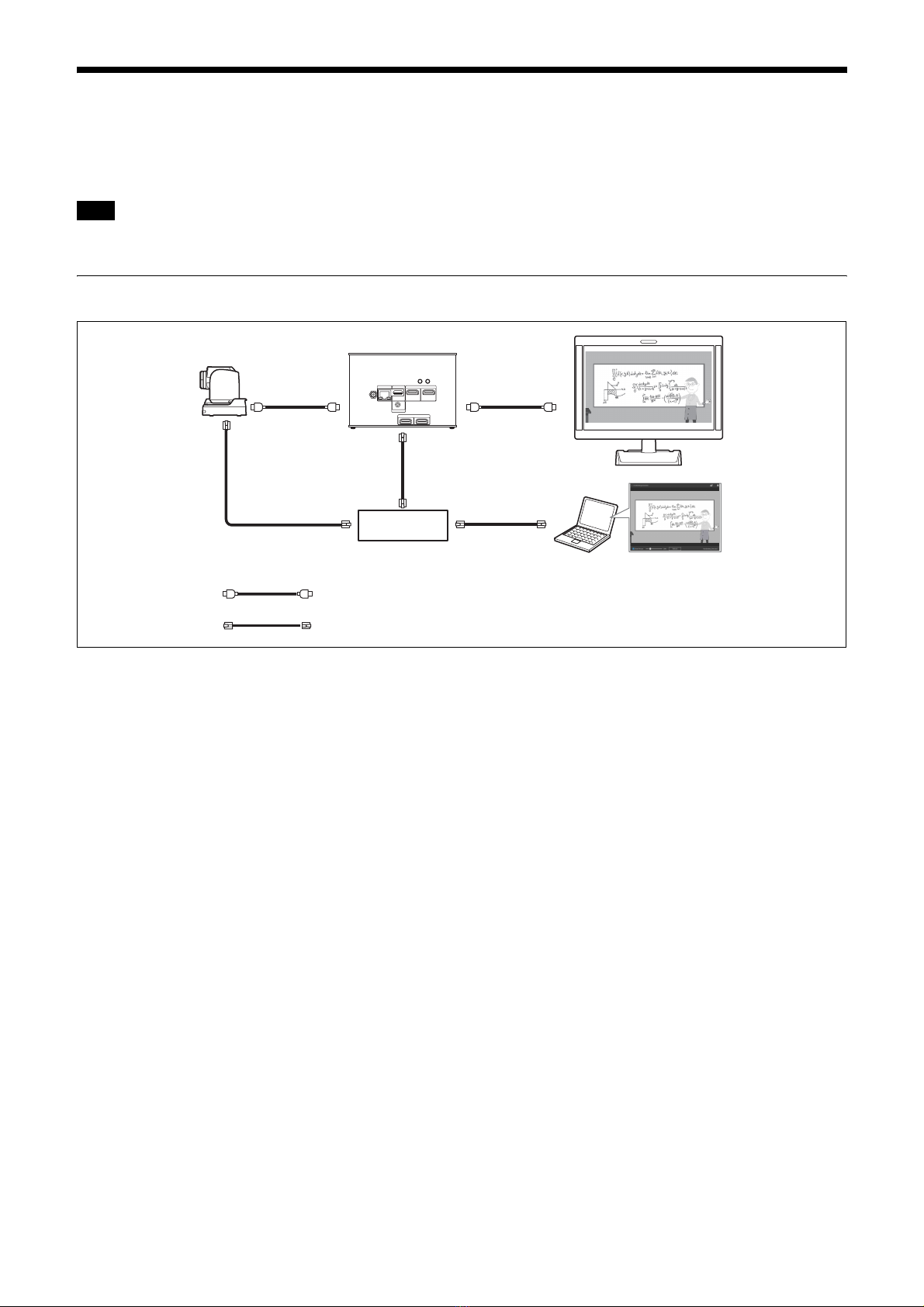
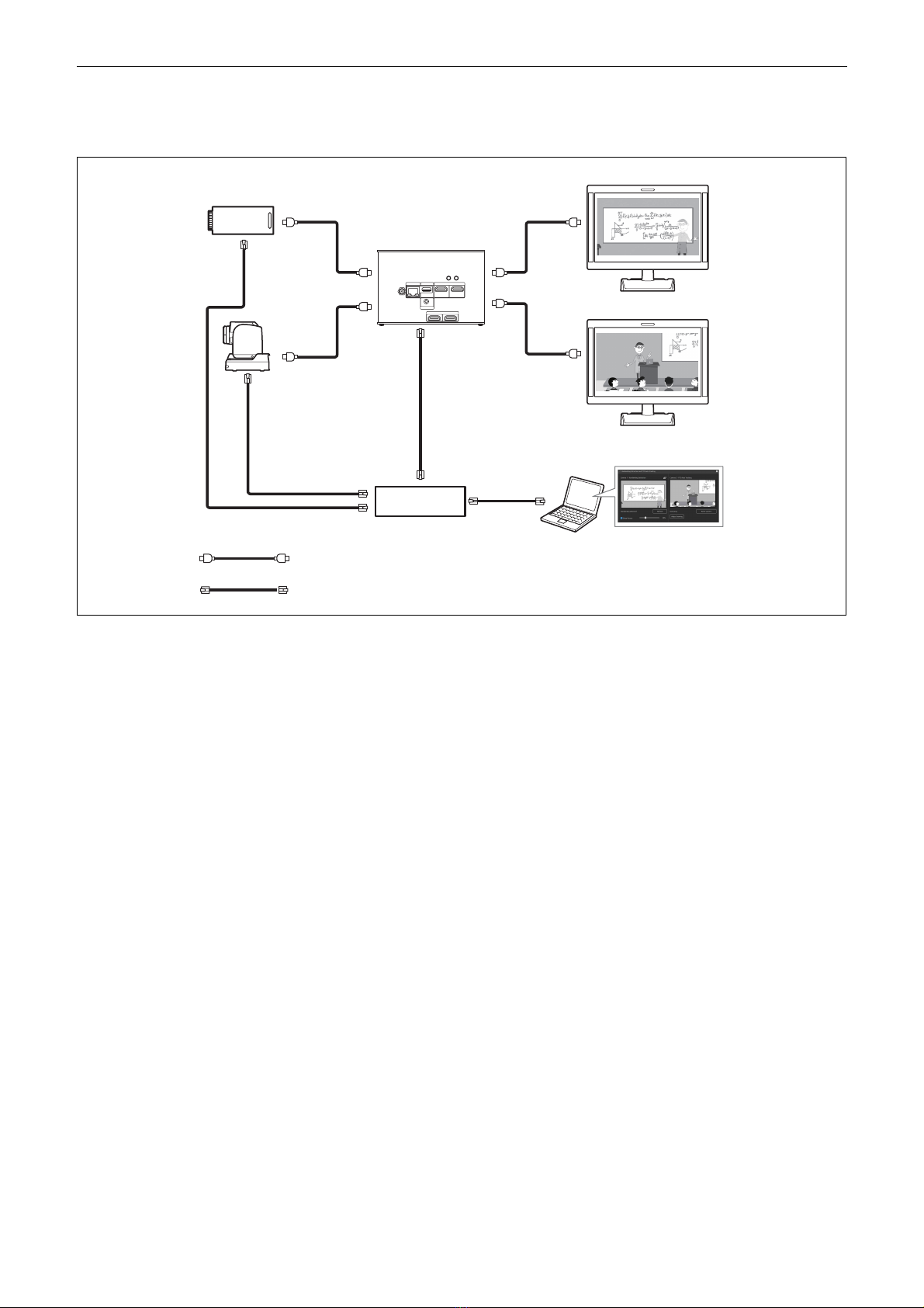
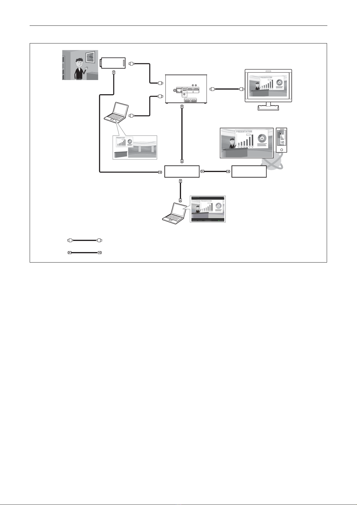
System Configuration ........................................... 7
Using single HDMI input and output ............. 7
Using two HDMI input and outputs ............... 8
Live streaming using RTMP protocol ............. 9
Installation and Connection
Installing .............................................................. 10
Mounting using mounting screws ................. 10
Connecting ........................................................... 10
Connecting to AC power supply ................... 10
Initial Setup
Setting Up a Computer ....................................... 11
Accessing the Unit from a Web Browser .......... 11
Screen Structure .................................................. 12
Configuring Initial Setup Items ......................... 12
Enabling option functions ............................. 12
Starting applications ..................................... 13
Checking notifications .................................. 13
Unit Setup (Common Settings)
Basic Operations in the Common Settings
Menu .................................................................... 14
Input/Output ....................................................... 14
Video ..................................................................... 15
Audio .................................................................... 16
Network ................................................................ 17
Security ................................................................ 18
[User] tab ...................................................... 18
[Access] tab .................................................. 18
[SSL] tab ....................................................... 19
[Referer] tab .................................................. 20
Streaming ............................................................. 21
[Streaming] tab ............................................. 21
[Codec] tab ................................................... 23
Starting/stopping RTMP streaming .............. 23
Licenses ................................................................ 24
[License] tab ................................................. 24
[History] tab ..................................................25
System ...................................................................25
[Information] tab ...........................................25
[Date & Time] tab .........................................26
[Initialize] tab ................................................26
[Update] tab ...................................................27
[EULA] tab ....................................................27
[Software] tab ................................................27
Application Setup and Operation
Configuring an Application ................................28
Common application setup operation ...........28
Running an application .................................28
Handwriting Extraction Application .................29
Preparation before setup ................................29
Configuring the Handwriting Extraction
application .....................................................30
Running the Handwriting Extraction
application .....................................................33
PTZ Auto Tracking Application .........................35
Preparation before setup ................................35
Configuring the PTZ Auto Tracking
application .....................................................36
Running the PTZ Auto Tracking
application .....................................................39
Close-up by Gesture Application .......................41
Preparation before setup ................................41
Configuring the Close-up by Gesture
application .....................................................41
Running the Close-up by Gesture
application .....................................................42
Chroma key-less CG Overlay Application ........43
Preparation before setup ................................43
Configuring the Chroma key-less CG Overlay
application .....................................................44
Running the Chroma key-less CG Overlay
application .....................................................45
Real-time Cropping Application ........................46
Preparation before setup ................................46
Configuring the Real-time Cropping
application .....................................................47
Running the Real-time Cropping
application .....................................................48
Registering a face in the face database ..........49
Editing the face database ...............................50
Appendix
Message List .........................................................51
LED indicators ..............................................51
Web browser display .....................................51
Troubleshooting ...................................................53
Supported Cameras and Available Camera
Functions ..............................................................54

4
Overview
Safety Regulations (supplied)
Describes the important points for safe use of the unit.
Be sure to read it.
Operating Instructions (This document/
Web)
These operating instructions describe the names of the
various parts of the unit, and installation, connection,
and operation methods.
Using This Manual
The Operating Instructions document is designed to be
read on a computer display.
The content you need to know in order to use the unit is
described here.
Read it before you operate the unit.
Jumping to a related page
When you read the instructions on a computer display
and click on the related part of the relevant page that is
being displayed, you jump to the related page. Relevant
pages can be searched easily.
Software display examples
The software displays described in this manual are
explanatory examples. Note that some displays may be
different from the ones that actually appear.
Printing the Operating Instructions
Depending on your system, certain displays or
illustrations in the Operating Instructions, when printed
out, may differ from those that appear on your screen.
NOTICE TO USERS
© 2018 Sony Corporation.
All rights reserved. This manual or the software
described herein, in whole or in part, may not be
reproduced, translated or reduced to any machine
readable form without prior written approval from
Sony Corporation.
SONY CORPORATION PROVIDES NO
WARRANTY WITH REGARD TO THIS
MANUAL, THE SOFTWARE OR OTHER
INFORMATION CONTAINED HEREIN AND
HEREBY EXPRESSLY DISCLAIMS ANY
IMPLIED WARRANTIES OF
MERCHANTABILITY OR FITNESS FOR ANY
PARTICULAR PURPOSE WITH REGARD TO
THIS MANUAL, THE SOFTWARE OR SUCH
OTHER INFORMATION. IN NO EVENT SHALL
SONY CORPORATION BE LIABLE FOR ANY
INCIDENTAL, CONSEQUENTIAL OR SPECIAL
DAMAGES, WHETHER BASED ON TORT,
CONTRACT, OR OTHERWISE, ARISING OUT
OF OR IN CONNECTION WITH THIS MANUAL,
THE SOFTWARE OR OTHER INFORMATION
CONTAINED HEREIN OR THE USE THEREOF.
Sony Corporation reserves the right to make any
modification to this manual or the information
contained herein at any time without notice. The
software described herein may also be governed by
the terms of a separate user license agreement.
• The terms HDMI and HDMI High-Definition
Multimedia Interface, and the HDMI Logo are
trademarks or registered trademarks of HDMI
Licensing Administrator, Inc. in the United States
and other countries.
• Microsoft, Windows, and Internet Explorer are
registered trademarks of United States Microsoft
Corporation in the United States and/or other
countries.
• JavaScript is a trademark or registered trademark of
Oracle Corporation, its affiliates or subsidiaries in
the United States and other countries.
• Adobe, Adobe Reader and Adobe Flash are
trademarks of Adobe Systems Incorporated.
• Google Chrome is a registered trademark of
Google Inc.
Other system names, product names appearing in this
document are trademarks or registered trademarks of
their respective manufacturers. Trademarked items
are not indicated by ® or ™ symbols in this
document.

5
Precautions Regarding
Personal Information
You can register the face of a person for the face
identification function of “Real-time Cropping” in the
unit. The registered face recognition information is
retained inside the unit. If the unit is accessed by an
unintended third party, there is a risk that the registered
face information could be viewed.
Precautions for
Preventing Access to
the Unit by an
Unintended Third Party
The unit may be accessible by an unintended third party
on the network, depending on the usage environment.
Changing the user name and password of the
administrator from the default settings is highly
recommended for security reasons. For details about
changing the user name and password, see “Security”
(page 18).
If the unit is accessed by an unintended third party, there
may be undesired effects, such as operations or settings
that may interfere with operation of the unit or the
registered face information could be viewed.
The unit can be fraudulently accessed in a network
environment where a device is connected or can be
connected to the network without the administrator’s
permission, or a computer or other network device
connected to the network can be used without any
permission. Connect to these environments at your own
risk. Also, use the SSL function, Referer check function,
or other security measures to prevent unauthorized
access to the unit. For details about functions, see
“Security” (page 18).
• The China model does not support the SSL function.
• To protect customer information, reset the settings of
this unit to the factory settings when lending or
transferring the unit to another person and when
disposing of the unit.
Features
The REA-C1000 is a device that analyzes video that is
input from a camera, computer, or other device, and
automatically generates video content in real-time that
previously would have required significant time and
human resources, and been expensive to create.
REA-C1000 configuration and application operation
can be controlled intuitively using a simple screen
displayed in a web browser on a computer connected to
the network.
The unit features the following applications.
Handwriting Extraction
This application identifies and extracts text and
diagrams drawn on a whiteboard or blackboard in real-
time, and renders them so that they appear in front of the
speaker.
PTZ Auto Tracking
This application tracks a moving target, and
automatically moves a remote camera to maintain
optimum compositing while shooting.
For details about supported remote cameras, contact
your distributor.
Close-up by Gesture
This application interprets specific gestures of people in
the video, and automatically zooms in on the
corresponding area. You can display two images (a wide
angle view and zoomed view) in real-time.
Chroma key-less CG Overlay
This application can generate simple CG composite
content in real-time, without requiring a studio with
dedicated green or blue screen facilities.
Real-time Cropping
This application simultaneously displays the wide-angle
view and a cropped view, from a single camera, by
cutting out a desired portion of the main view in real-
time, creating the effect of shooting with two cameras.
The focus area extraction function includes a “Focus
Area Cropping” function that automatically tracks and
extracts a specific object, and a “Fixed Area Cropping”
function that extracts a specified area. The cropped view,
simultaneously output with the main view, can be
selected from two configured areas.
Notes
Note

6
Location and Function
of Parts
A12 V (DC power input) connector
Connect to an AC adapter (not supplied).
For details about supported AC adapters, contact
your distributor. Use of other AC adapters may
cause a fire or malfunction.
BLAN (network) connector (RJ-45)
Connect to a 10BASE-T, 100BASE-TX, or
1000BASE-T switching hub using a LAN cable (not
supplied, category 5 or higher, shielded twisted
pair).
• For safety, do not connect the connector for
peripheral device wiring that might have
excessive voltage to this port. Follow the
instructions for this port.
• When connecting this product to a network,
connect via a system that provides a protection
function, such as a router or firewall. If connected
without such protection, security issues may
occur.
CEXTERNAL connector
Not supported in the current software version.
DHDMI OUT 1/HDMI OUT 2 connectors
Connect to the HDMI input connectors of a display,
projector, or other video device to display the output
video from the unit.
ESTATUS button/LED
Press and hold the button for 5 seconds with the unit
turned so that the POWER LED starts flashing
green. Press and hold the POWER button for
3 seconds while the LED is flashing to restart the
unit and restore all settings, including network
settings, to their factory default settings.
Lights in green when the unit is operating normally.
Lights in red when not connected to the network.
Flashes in red when an error (such as an over-
temperature alarm) occurs in the unit.
FPOWER button/LED
Power is supplied and the POWER LED lights in
green when the unit is connected to an outlet using
an AC adapter (not supplied) and power cord.
To turn the unit off, press and hold the button for
3 seconds. The POWER LED goes out when the
unit turns off.
To turn the unit on again, press the POWER button.
The POWER LED lights in green.
In standby state, the power LED lights in orange.
For details about switching to standby state, see
“[Standby]” (page 26).
GHDMI IN 1/HDMI IN 2 connectors
Connect to the HDMI output connectors of a
camera, computer, or other video device.
HMIC IN connector
Connect to the audio output connector of an audio
device.
IMounting screw holes (four locations on
bottom panel)
Use to mount the unit.
For details, see “Mounting using mounting screws”
(page 10).
JRatings label (bottom panel)
This label shows the name of the unit and its
electrical ratings.
Note
Notes
Note
12 3 456
78
0
9 9
Important

7
System Configuration
The unit can be arranged into various system configurations with other devices (not supplied). The diagram below
shows a typical system configuration.
We recommend that you build a 1000BASE-T network if using the streaming function.
Using single HDMI input and output
Tip
Camera
Monitor
Router
Computer for setup
HDMI cable
LAN cable (category 5e or higher, shielded twisted pair)
REA-C1000

8
Using two HDMI input and outputs
Using two HDMI inputs and outputs allows simultaneous use of the PTZ Auto Tracking and Handwriting Extraction
functions.
REA-C1000
Camera
HDMI cable
LAN cable (category 5e or higher, shielded twisted pair)
Router
Computer for setup
Camera
Monitor
Monitor

9
Live streaming using RTMP protocol
REA-C1000
Camera
HDMI cable
LAN cable (category 5e or higher, shielded twisted pair)
Router
Computer for setup
Camera image
Monitor (optional)
Streaming
service
WAN
Content for compositing

10
Installation and Connection
Installing
Install the unit on a level surface, such as a desktop.
If, unavoidably, you need to mount the unit on an
inclined surface, mount the unit using the mounting
screw holes on the bottom panel to prevent the unit from
falling.
• Cables may catch on the connector shell of other
cables connected to adjacent connectors and not be
connected properly, depending on the cables used.
Check that the cables can be used with the unit
beforehand.
• Mount the unit so that no strong force is applied to the
cables connected to the unit. Cables may be pulled out
or the unit may malfunction.
• Notes about temperature rise of the unit
– The unit may become hot during use. This is not a
malfunction.
– Avoid use where the unit is in direct contact with
exposed skin for extended periods.
– The temperature rise may occur quickly in high-
temperature environments.
Mounting using mounting screws
Attach the unit using the four mounting holes (for M3
screws) on the bottom panel. Use M3 screws that meet
the following criteria. Attach the unit with the screws
against a flat surface, without ridges or undulations, and
tighten securely.
4= 3 mm to 8 mm
Connecting
Connecting to AC power supply
Connect to the AC power supply using an AC adapter
(not supplied) and power cord.
The POWER LED lights green when power is supplied.
After the unit has powered up, the STATUS LED lights
green when access from a web browser becomes
enabled.
• For details about supported AC adapters (not
supplied), contact your distributor. Use of other AC
adapters may cause a fire or malfunction.
• Connect the power supply to the unit only after
powering on the other peripheral devices.
Notes
M3 screw
Notes

11
Initial Setup
Perform the following configuration when starting the
unit for the first time. This configuration is performed by
the administrator.
Setting Up a Computer
Prepare a computer and connect it to the network. The
recommended operating environment is given below.
OS: Windows 10 Pro (32-bit version/64-bit version)
Web browser: Google Chrome Ver. 85 or later
• Turn off tablet mode.
• Do not use the Back button of the browser.
• JavaScript is used for the web page display when
accessing the unit. The web page may not display
correctly if your computer uses certain software, such
as anti-virus software.
Accessing the Unit from
a Web Browser
Perform the following configuration to enable access of
the unit from a web browser.
1
Assign an IP address to the unit using
RM-IP Setup Tool.
The IP address of the unit is obtained automatically
using DHCP, but you can change it using RM-IP
Setup Tool if required.
For details about setting the IP address, refer to the
RM-IP Setup Tool guide.
Download RM-IP Setup Tool and the RM-IP Setup
Tool guide separately from the following website.
www.sony.net/CameraSystem
2
Check the IP address of the unit.
You can check the IP address using RM-IP Setup
Tool.
For details about checking the IP address, refer to
the RM-IP Setup Tool guide.
3
Start a web browser on the computer, and
enter the IP address of the unit in the
address bar.
4
Access the unit.
User name and password authentication is required
to access the unit. The user name and factory-set
password of the unit are given below.
User name: admin
Password: Admin_1234
In RM-IP Setup Tool, the unit is detected on the
“Camera” tab. You can check and set the name and IP
address of the unit from RM-IP Setup Tool in the same
way as for a remote camera. By default, “Device0” is
displayed as the name of the unit.
Notes Tip
Tip

12
Screen Structure
The following screen appears in the web browser when
you access the unit.
You can configure the unit, and configure and run
applications from this screen.
The initial setup screen appears by default when you
access the unit in its factory default state.
A[Applications]
Click to select, configure, or run an application.
Clicking displays the available applications.
Selecting an application displays the setup and run
screen of the application.
For details about selecting, configuring, and running
applications, see “Application Setup and Operation”
(page 28).
BCommon settings menu
Click to configure common settings of the unit, such
as video and network settings.
COperation/settings area
Displays the selected menu item screen or
application setup screen.
DNotifications button
A red indicator is displayed on the notifications
button when there is a notification relating to the
status of the unit. Click it to display the notifications
dialog.
Configuring Initial Setup
Items
Access the unit in the factory default state, and configure
the following items.
[EULA]
Displays the EULA (End User License Agreement).
[Language]
Specify the display language of the screen. For details
about configuration, see “System” (page 25).
[Administrator]
Set [User Name] and [Password] for the administrator.
For details about configuration, see “Security”
(page 18).
[Network]
Configure the network settings for connection between
the unit and a computer. For details about configuration,
see “Network” (page 17).
[Date & Time]
Set the date and time on the unit. For details about
configuration, see “System” (page 25).
[System Frequency]
Set the system frequency for the unit to support. For
details about configuration, see “Video” (page 15).
• Be sure to change the default user name and password
used when you first start the unit. After changing the
user name and password, reauthentication using the
new user name and password is required.
• If the network settings are changed, access the unit
again using the changed network information.
• The unit must be restarted after completing the initial
setup.
Enabling option functions
Option functions must be enabled before configuring or
running an application. To enable an option function,
you must activate a pre-installed license or purchase and
install a license. For details about installing a license,
see “Licenses” (page 24).
Note
Notes

13
Licenses
The following option function licenses are available for
the unit.
• Handwriting Extraction license
Enables the Handwriting Extraction function.
REA-L0100: Permanent license
REA-L0106: Period license (180 days)
REA-L0112: Period license (365 days)
• PTZ Auto Tracking license
Enables the PTZ Auto Tracking function.
REA-L0200: Permanent license
• Close-up by Gesture license
Enables the Close-up by Gesture function.
REA-L0300: Permanent license
REA-L0306: Period license (180 days)
REA-L0312: Period license (365 days)
• Chroma key-less CG Overlay license
Enables the Chroma key-less CG Overlay function.
REA-L0400: Permanent license
REA-L0401: Period license (30 days)
REA-L0403: Period license (90 days)
REA-L0412: Period license (365 days)
• Focus Area Cropping license
Enables the Focus Area Cropping function.
REA-L0500: Permanent license
REA-L0501: Period license (30 days)
REA-L0503: Period license (90 days)
REA-L0512: Period license (365 days)
Pre-installed licenses
You can trial test option functions by activating pre-
installed licenses on the unit, without having to purchase
and install any licenses.
For details about activation, see “Licenses” (page 24).
• Activating pre-installed licenses enables you to trial
test option functions for a limited time only. However,
if a period license is installed for the same function as
a trial license which has not been activated, that trial
license becomes disabled.
• For details about purchasing licenses, contact your
distributor.
Starting applications
Access the unit from a web browser to select and run an
application.
A license may need to be enabled to run an application.
For details about configuring applications, see
“Application Setup and Operation” (page 28).
Tip
If the unit is turned off normally while an application is
running, the application will automatically restart the
next time the unit is turned on.
Checking notifications
You can check the status of the unit and the status of
connections with external devices in the notifications
dialog.
The notifications dialog is displayed automatically
when the status of the unit changes. You can also display
the dialog by clicking the notifications button at the top
right of the screen.
For details about notifications, see “Message List”
(page 51).
Notes
Tip

14
Unit Setup (Common Settings)
This section describes the common settings of the unit
on each menu page.
This configuration is performed by the administrator.
Basic Operations in the
Common Settings Menu
Click an item in the common settings menu on the left
side of the screen to display the setup screen for that
item.
If the setup screen displays multiple tabs, click on a tab
to switch the display in the setup screen.
The following buttons at the bottom of the setup screen
are common for all items.
[OK]: Click to apply the settings. The settings are not
applied on the unit until you click this button.
[Cancel]: Click to discard the settings and return to the
previous state.
Only those items that are currently configurable are
displayed. Items that are grayed out cannot be
configured. Functions that are not installed are not
displayed.
Input/Output
Use to configure the connected camera that supplies the
video input of the unit.
You can preview and adjust the video from a camera or
device connected to the HDMI IN 1 connector or HDMI
IN 2 connector.
[HDMI IN 1] / [HDMI IN 2]
Select the connector to which the camera or device
whose video you want to preview is connected.
Preview image
When a camera or other video device connected to the
HDMI IN 1 connector or HDMI IN 2 connector is
operating normally, a preview of the image from the
camera or device is displayed.
[Nickname]
Enter a nickname for the connected camera or device.
This is used as an identifier when configuring
applications.
[IP Address]
Enter the IP address of the remote camera to control a
Sony remote camera from the unit using VISCA over IP.
To clear the IP address, enter “0.0.0.0”.
[Model Name]
Select the model name or enter an arbitrary model name
for the remote camera to control from the unit using
VISCA over IP.
When a supported camera is connected. the following
camera functions can be controlled by the unit. For
correct camera operation, configure the [IP Address]
and [Model Name] settings.
• Pan, tilt, and zoom functions
– Control using PTZ Auto Tracking application
• Exposure and white balance functions
– Control using Handwriting Extraction application
• Tally lamp function
– Control using PTZ Auto Tracking application
– Control using Real-time Cropping application
Note
Note

15
For details about supported cameras and their available
camera functions, see “Supported Cameras and
Available Camera Functions” (page 54).
To use the PTZ Auto Tracking application, be sure to
connect a camera that supports pan, tilt, and zoom
functions.
Video
Use to configure the system frequency and output video
of the unit.
[System Frequency]
Select the system frequency.
[59.94Hz]: Supports input and output video in 59.94 Hz
systems.
[50Hz]: Supports input and output video in 50 Hz
systems.
HDMI OUT 1
Set the output image size and frame rate of the video
output from the HDMI OUT 1 connector.
[EDID]: Automatically determine and output a video
image that is compatible with the connected output
device.
[3840×2160 / 29.97P]: Output at 3840×2160 29.97P.
(Available only when the system frequency is
59.94 Hz)
[3840×2160 / 25P]: Output at 3840×2160 25P.
(Available only when the system frequency is 50 Hz)
[1920×1080 / 59.94P]: Output at 1920×1080 59.94P.
(Available only when the system frequency is
59.94 Hz)
[1920×1080 / 50P]: Output at 1920×1080 50P.
(Available only when the system frequency is 50 Hz)
HDMI OUT 2
Set the output image size and frame rate of the video
output from the HDMI OUT 2 connector.
[EDID]: Automatically determine and output a video
image that is compatible with the connected output
device.
[1920×1080 / 59.94P]: Output at 1920×1080 59.94P.
(Available only when the system frequency is
59.94 Hz)
[1920×1080 / 50P]: Output at 1920×1080 50P.
(Available only when the system frequency is 50 Hz)

16
If the system frequency is changed, you must restart the
unit.
Audio
Use to configure the audio of the unit.
To enable the audio function
Select [Enable] in [Send]. The following items can be
configured when the audio function is enabled.
[Audio Input Selection]
Select the audio data ([HDMI IN] or [MIC IN]) that is
output on [HDMI OUT 1] and [HDMI OUT 2].
[HDMI IN]: Use the audio data that is input on the
HDMI IN connector.
[MIC IN]: Use the audio data that is input on the MIC
IN connector.
[Mic Input Setting]
Set the audio data that is input from the microphone
connected to the MIC IN connector.
[Delay]: Set the audio delay so that the audio data input
from the microphone is synced with the video data
that is input from HDMI IN.
[Volume]: Set the volume.
Note

17
Network
Use to configure the network settings for connection
between the unit and a computer.
[MAC Address]: Displays the MAC address of the unit.
[Ethernet Status]: Displays the current
communications speed.
[HTTP Port Number]: Displays the port number for
HTTP.
[HTTPS Port Number]: Displays the port number for
HTTPS.
The China model does not support the SSL function.
To obtain an IP address (IPv4) automatically
from a DHCP server
Place a check mark in [Obtain an IP address
automatically (DHCP)] to automatically acquire the IP
address, subnet mask, and default gateway.
[IP Address]: Displays the current IP address.
[Subnet Mask]: Displays the current subnet mask
value.
[Default Gateway]: Displays the current default
gateway.
If you select [Obtain an IP address automatically
(DHCP)], check that a DHCP server is operating on the
network.
To specify a fixed IP address (IPv4)
Clear the [Obtain an IP address automatically (DHCP)]
checkbox and enter the following items.
[IP Address]: Enter the IP address of the unit.
[Subnet Mask]: Enter the subnet mask value.
[Default Gateway]: Enter the default gateway.
To obtain an IP address (IPv6) automatically
Place a check mark in [Obtain IPv6 address
automatically] to automatically acquire the IP address,
prefix length, and default gateway.
[IPv6 Address 1] / [IPv6 Address 2]: Displays the
current IPv6 addresses.
[Link-Local IP Address]: Displays the current IPv6
link-local IP address.
[Prefix Length]: Displays the current prefix length.
[IPv6 Default Gateway]: Displays the current IPv6
default gateway.
• If you select [Obtain IPv6 address automatically],
check with the network administrator whether IPv6
assignment is supported.
• Operation in a multi-prefix environment is not
supported, and communication may not operate
correctly.
To specify a fixed IP address (IPv6)
Clear the [Obtain IPv6 address automatically] checkbox
and enter the following items.
[IPv6 Address 1]: Enter the IP address of the unit.
[Prefix Length]: Enter the prefix length.
[IPv6 Default Gateway]: Enter the default gateway.
To obtain the DNS server address
automatically
Place a check mark in [Obtain DNS server address
automatically] to automatically acquire the addresses of
the primary DNS server and secondary DNS server.
[Primary DNS Server]: Displays the current primary
DNS server IP address.
[Secondary DNS Server]: Displays the current
secondary DNS server IP address.
To obtain the DNS server address automatically, either
[Obtain an IP address automatically (DHCP)] or [Obtain
IPv6 address automatically] must be enabled. Check
with the network administrator whether the environment
supports a server address being obtained automatically.
To specify the DNS server address manually
Clear the [Obtain DNS server address automatically]
checkbox and enter the following items.
[Primary DNS Server]: Enter the IP address of the
primary DNS server.
[Secondary DNS Server]: Enter the IP address of the
secondary DNS server.
Note
Note
Notes
Note

18
Security
Use to configure settings relating to security on the unit.
The screen consists of [User], [Access], [SSL], and
[Referer] tabs.
[User] tab
Use to configure users.
You can configure the user name, password, and user
access permissions of one administrator and nine
general users.
Administrator and general users
Users on the unit are categorized into administrator and
general users.
The administrator can access all functions of the unit,
including configuration of the unit and applications. A
general user has permission to monitor running
applications only.
[Administrator], [User 1] to [User 9]
Set the following items for the administrator and each
general user.
[User Name]: Enter a user name comprising 5 to 16
characters.
[Current Password]: Enter the currently configured
password comprising 8 to 64 characters.
[New Password]: Enter the new password you want to
set comprising 8 to 64 characters.
[Re-type Password]: Re-enter the new password you
want to set to verify the password.
Administrator permission selection: To grant
administrator access to a user, select
[Administrator]. To set a general user without
administrator access, select [User].
• The following characters are valid in user names and
passwords. Include at least one upper-case letter, one
lower-case letter, and one number in passwords.
– Alphanumeric characters
– Symbols (!$%'()=-~^|@`[{}]_/?<>+*.)
• A user name and new password must be configured
when adding a user.
• To change the user information, all items must be
specified again.
• When deleting a user, leave all fields other than
[Current Password] blank.
[Access] tab
Use to configure the security function to restrict the
computers that can access the unit.
Similarly, you can also configure security for each
network when using IPv6.
To enable IP address restrictions
Select [Enable] for [Access restricted by IP address],
and configure the following items.
[Default Policy]
Select [Allow] or [Deny] to allow or deny access from
computers whose network address is outside the ranges
configured in [Network Address/Subnet 1] to [Network
Address/Subnet 10].
[Network Address/Subnet 1] to [Network
Address/Subnet 10]
Enter the network address/subnet mask value that you
want to allow or deny access.
You can specify up to ten network addresses and subnet
mask values.
Enter a subnet mask value of 8 to 32 (8 to 128 for IPv6).
Set access to [Allow] or [Deny] individually for each
network address/subnet mask.
Notes

19
• The subnet mask value indicates the number of bits
that are masked off from the left. For example, the
subnet mask value for 255.255.255.0 is 24.
If you set “192.168.0.0/24” and [Allow], computers
having an IP address between 192.168.0.0 and
192.168.0.255 have access allowed.
• You can access the unit even from a computer with an
IP address whose access right is set to [Deny], if you
enter the user name and password set for the
Administrator using the [User] tab of the [Security]
page on the authentication screen.
[SSL] tab
Use to configure the SSL or TLS function (hereinafter
referred to as SSL). Configuring these settings allows
the unit to use SSL communication with client devices.
• The China model does not support the SSL function.
• When using the SSL function, always configure the
settings after setting the date and time of the unit. If
the date and time are not set correctly, it may not be
possible to connect to the unit using a web browser.
• Reload the web browser after you change the SSL
settings.
• Software version 2.00 and later employs “TLS1.2”
encryption for high-security communication.
To enable the SSL function
Select [Enable] from the [SSL Function] pull-down
menu to enable the SSL function.
When [Enable (Allow HTTP connection for some
clients)] is selected, both SSL connections and HTTP
connections are allowed.
When [Enable] is selected, only SSL connections are
allowed.
Precautions with SSL connections
When you use only SSL connections with the SSL
function set to [Enable], you will not be able to access
the unit if the SSL function is not working properly.
In this case, you must reset the unit to the factory
settings. (All settings will be initialized.)
To avoid this, check that SSL connection can be
established before configuration by performing the
following steps.
1
Set the SSL function to [Enable (Allow HTTP
connection for some clients)].
Always select [Enable (Allow HTTP connection for
some clients)]. If it is not selected and the SSL
connection fails, you will not be able to access the
unit.
2
Click the [OK] button to close the web
browser.
3
Display the web browser using an SSL
connection.
4
After confirming that SSL connection is
possible, set the SSL function to [Enable].
If the SSL connection fails while checking the
connection, you can select [Enable (Allow HTTP
connection for some clients)] to connect using an HTTP
connection. Check the settings on the [SSL] tab using an
HTTP connection, and then check the SSL connection
again.
[Certificate Options]
Select the certificate installation mode.
[Use an external certificate]: This mode uses a
certificate (including private key information) issued
by a CA. PKCS#12 and PEM certificate formats are
supported.
[Use a self-signed certificate (For test use)]: This
mode uses a certificate and private key pair
generated as described in “To generate a self-signed
certificate” (page 20). The private key information
corresponding to the certificate is stored within the
unit.
You do not need to install an external certificate, but
validating its existence, which is one of the SSL
functions, is not possible for the following reasons.
• Self-signing uses the private key generated in the
unit.
• A preconfigured value is set for the Distinguished
Name (Common Name, and so on).
• The certificate is not issued by a CA trusted by the
customer’s system.
For reasons of security, we recommend using this
certificate only when there is no problem and a lack
of total security is not a concern, such as for testing.
• When [Use a self-signed certificate (For test use)] is
selected, a security alert appears when initiating an
SSL connection with a web browser.
Tips
Notes
Note
Tip
Notes

20
• SSL connection may not be possible depending on the
type of certificate installed in the unit.
To import a certificate
Click the [Browse] button at the bottom right of the
setup screen and select the certificate. Click the [OK]
button in the file selection dialog to import the selected
file into the unit.
• The import process is invalid if the selected file is not
a certificate or if the format of the imported certificate
is not allowed.
• In software version 2.00 and later, the following
insecure certificates are disabled.
– Certificates with a private key of 1024 bits or
smaller
– Certificates that use a weak algorithm, such as
MD5/SHA1
To generate a self-signed certificate
A self-signed certificate must be generated when [Use a
self-signed certificate (For test use)] is selected in
[Certificate Options].
Click the [Generate] button to generate a self-signed
certificate in the unit.
Clicking the [Generate] button again after generating a
self-signed certificate will update the self-signed
certificate stored in the unit.
• Make sure to set the date and time on the unit before
performing this operation. If the date and time are not
set correctly, it may not be possible to connect to the
unit using a web browser.
• Before clicking the [Generate] button to generate a
self-signed certificate, select [Use a self-signed
certificate (For test use)] in [Certificate Options] and
click the [OK] button.
To display the certificate contents
When the certificate has been configured in the unit
correctly, information from the certificate appears in
[Status], [Issuer DN], [Subject DN], [Available Period],
and [Extended Key Usage].
[Status]
Displays whether the status of the certificate is valid or
invalid. The following status types are displayed.
[Valid]: The certificate is correctly stored and
configured.
[Invalid]: The certificate is not correctly stored and
configured. If invalid, possible causes are as follows:
• [Use an external certificate] is selected but the
private key password included in the certificate is
not specified correctly.
• [Use an external certificate] is selected but the
private key included in the certificate is not
encrypted. Or the private key password is specified
but is not encrypted.
• [Use an external certificate] is selected but the
required private key is not included in the
certificate.
• [Use a self-signed certificate (For test use)] is
selected but a self-signed certificate has not been
generated.
When the certificate to be imported is in PKCS#12
format and the private key password is not specified
correctly, “<Put correct private key password>” is
displayed in the [Issuer DN], [Subject DN], [Available
Period], and [Extended Key Usage] fields. Specify the
correct private key password.
To delete the imported certificate or self-signed
certificate
Click the [Delete] button on the setup screen to delete
the imported certificate or self-signed certificate.
To specify the private key password
Enter a password comprising up to 50 characters for the
private key included in the certificate in [Private Key
Password]. Entry is supported only when [Certificate
Options] is set to [Use an external certificate].
Leave the field for this parameter blank if the private key
included in the certificate is not encrypted.
To enter the private key password, click the [Reset]
button and enter a password.
Click the [Cancel] button at the bottom of the screen if
you want to cancel changing the private key password
after clicking the [Reset] button. Note that clicking the
[Cancel] button also restores all other setting items on
the [SSL] tab to the previous settings.
[Referer] tab
Use the [Referer] tab to configure the Referer check
function. “Referer Check” is a function that checks
whether the web page which requested the access is
legitimate when the unit is accessed from an external
source. If the web page cannot be confirmed as
legitimate, access is denied.
If you want to access the unit from a web page other than
one that the unit provides, register the host name and
port number that hosts the web page on this tab.
Notes
Notes
Note
Note
Other manuals for REA-C1000
1
Table of contents