manuals.online logo
Brands
  1. Home
  2. •
  3. Brands
  4. •
  5. Sony
  6. •
  7. Camcorder
  8. •
  9. Sony DCR-TRV33 PIXELA ImageMixer v1.5 User manual

Sony DCR-TRV33 PIXELA ImageMixer v1.5 User manual

Other manuals for DCR-TRV33 PIXELA ImageMixer v1.5

3

This manual suits for next models

1

Other Sony Camcorder manuals

Sony Handycam NEX-VG10 User manual

Sony

Sony Handycam NEX-VG10 User manual

Sony Handycam CCD-TR416 User manual

Sony

Sony Handycam CCD-TR416 User manual

Sony Super HAD CCD II SSC-FB531 User manual

Sony

Sony Super HAD CCD II SSC-FB531 User manual

Sony HDCAM HDW-700A User manual

Sony

Sony HDCAM HDW-700A User manual

Sony Handycam HDR-CX240 Reference guide

Sony

Sony Handycam HDR-CX240 Reference guide

Sony UMC-S3C User manual

Sony

Sony UMC-S3C User manual

Sony DCR-TRV38 PIXELA ImageMixer v1.5 User manual

Sony

Sony DCR-TRV38 PIXELA ImageMixer v1.5 User manual

Sony FCBEH6500 User manual

Sony

Sony FCBEH6500 User manual

Sony PDW-F355L User manual

Sony

Sony PDW-F355L User manual

Sony PMW-500 Owner's manual

Sony

Sony PMW-500 Owner's manual

Sony Handycam CCD-FX520 User manual

Sony

Sony Handycam CCD-FX520 User manual

Sony Handycam DCR-SR46 User manual

Sony

Sony Handycam DCR-SR46 User manual

Sony PMW10MD User manual

Sony

Sony PMW10MD User manual

Sony CX160E User manual

Sony

Sony CX160E User manual

Sony HDC-900 Series User manual

Sony

Sony HDC-900 Series User manual

Sony DXC-H10 User manual

Sony

Sony DXC-H10 User manual

Sony Handycam DCR-VX1000 User manual

Sony

Sony Handycam DCR-VX1000 User manual

Sony Handycam HDR-UX10 User manual

Sony

Sony Handycam HDR-UX10 User manual

Sony Handycam DCR-SX73E User manual

Sony

Sony Handycam DCR-SX73E User manual

Sony PDW-680 User manual

Sony

Sony PDW-680 User manual

Sony Handycam DCR-TRV940 User manual

Sony

Sony Handycam DCR-TRV940 User manual

Sony Handycam DCR-SR50E User manual

Sony

Sony Handycam DCR-SR50E User manual

Sony PXW-X400 Installation guide

Sony

Sony PXW-X400 Installation guide

Sony Handycam DCR-SR62 User manual

Sony

Sony Handycam DCR-SR62 User manual

Popular Camcorder manuals by other brands

Vivitar DVR 830XHD owner's manual

Vivitar

Vivitar DVR 830XHD owner's manual

Panasonic HX-WA20PP Service manual

Panasonic

Panasonic HX-WA20PP Service manual

Canon FS1 instruction manual

Canon

Canon FS1 instruction manual

Sharp VL-H400S Operation manual

Sharp

Sharp VL-H400S Operation manual

Panasonic AJ-D900WAP operating instructions

Panasonic

Panasonic AJ-D900WAP operating instructions

Samsung VP-D6550 Owner's instruction book

Samsung

Samsung VP-D6550 Owner's instruction book

Naxa NDC-402 instruction manual

Naxa

Naxa NDC-402 instruction manual

LG L320-BN owner's manual

LG

LG L320-BN owner's manual

Vivitar DVR 865HD user manual

Vivitar

Vivitar DVR 865HD user manual

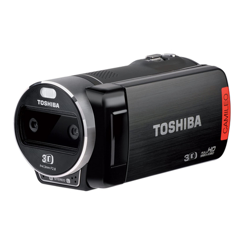
Toshiba CAMILEO Z100 user guide

Toshiba

Toshiba CAMILEO Z100 user guide

Panasonic NV-VS40B operating instructions

Panasonic

Panasonic NV-VS40B operating instructions

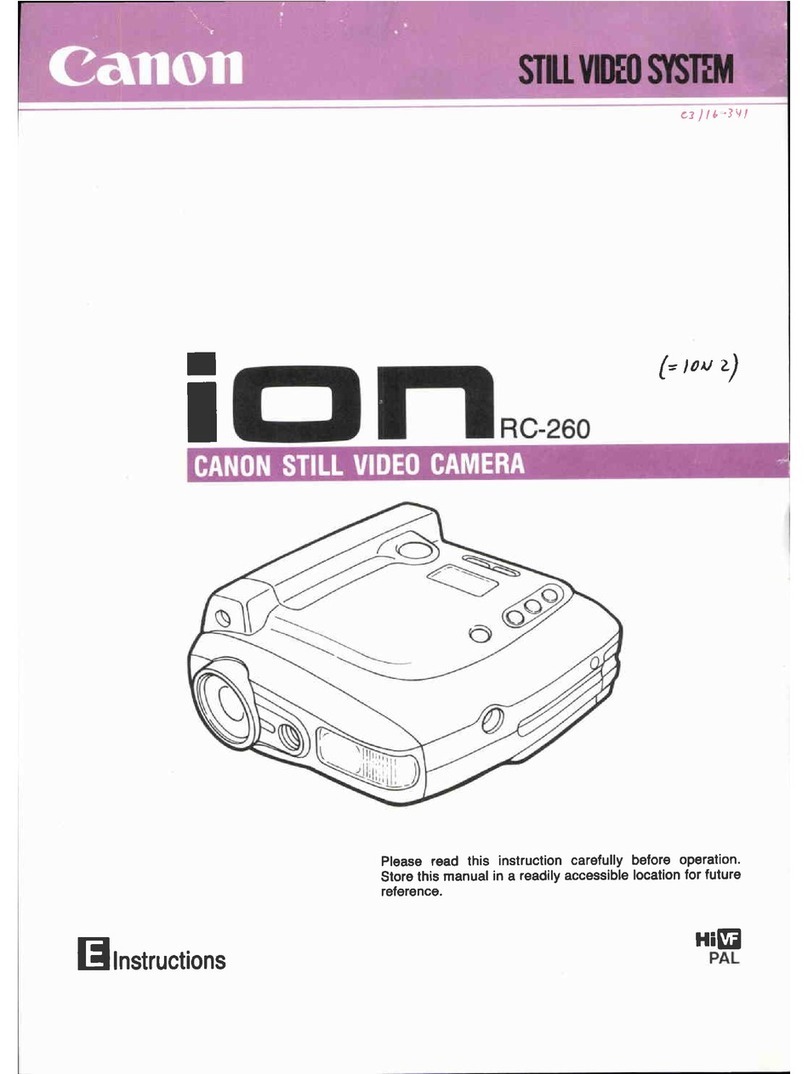
Canon RC 260 instructions

Canon

Canon RC 260 instructions

Brinno TimeLapse TLC200 user manual

Brinno

Brinno TimeLapse TLC200 user manual

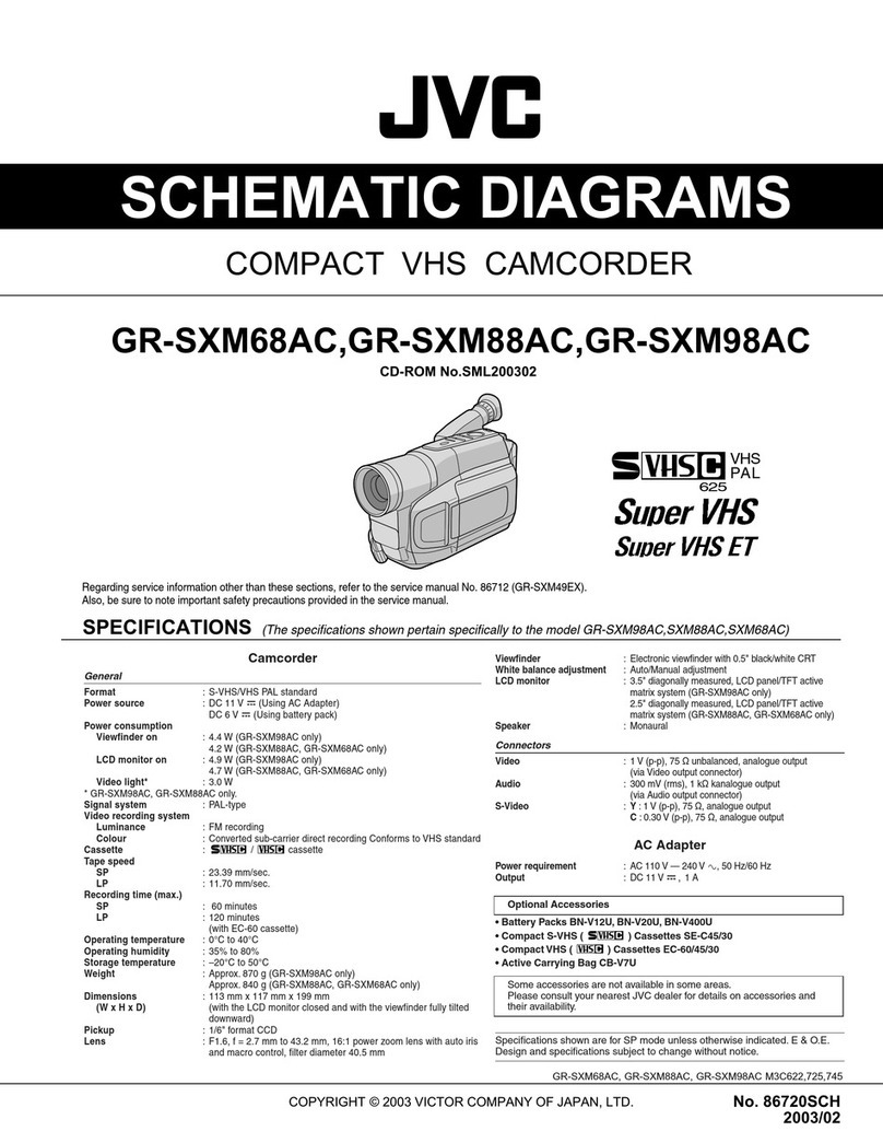
JVC GR-SXM68AC Schematic diagram

JVC

JVC GR-SXM68AC Schematic diagram

MYDLINK DCS-6100LH Quick installation guide

MYDLINK

MYDLINK DCS-6100LH Quick installation guide

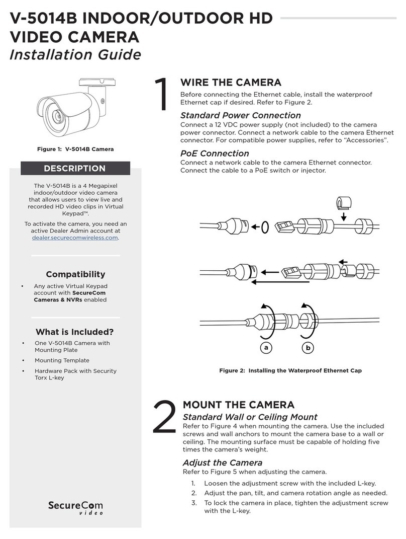
SECURECOM V-5014B installation guide

SECURECOM

SECURECOM V-5014B installation guide

JVC AA-V15EG instruction manual

JVC

JVC AA-V15EG instruction manual

Canon LEGRIA HV40 instruction manual

Canon

Canon LEGRIA HV40 instruction manual

manuals.online logo
manuals.online logoBrands
  • About & Mission
  • Contact us
  • Privacy Policy
  • Terms and Conditions

Copyright 2025 Manuals.Online. All Rights Reserved.

SERVICE MANUAL
• INSTRUCTION MANUAL is shown at the end of this document.
Revision History
Revision History
Ver 1.0 2003. 02
LEVEL 1
Link
SELF DIAGNOSIS FUNCTION
ORNAMENTAL PARTSSPECIFICATIONS
SELF DIAGNOSIS FUNCTION
ORNAMENTAL PARTSSPECIFICATIONS
Link
DIGITAL VIDEO CAMERA RECORDER
Z MECHANISM
Photo : DCR-TRV33
DCR-TRV33/TRV33E
RMT-814
US Model
Canadian Model
Korea Model
DCR-TRV33
AEP Model
UK Model
North European Model
East European Model
Chinese Model
Australian Model
DCR-TRV33E
E Model
Hong Kong Model
Tourist Model
DCR-TRV33/TRV33E
—2 —
DCR-TRV33/TRV33E
SPECIFICATIONS
COVER
COVER
Video camera
recorder
System
Video recording system
2 rotary heads
Helical scanning system
Audio recording system
Rotary heads, PCM system
Quantization: 12 bits (Fs 32 kHz,
stereo 1, stereo 2), 16 bits
(Fs 48 kHz, stereo)
Video signal
PAL colour, CCIR standards
Usable cassette
Mini DV cassette with the
mark printed
Tape speed
SP: Approx. 18.81 mm/s
LP: Approx. 12.56 mm/s
Recording/playback time
(using cassette DVM60)
SP: 1 hour
LP: 1.5 hours
Fastforward/rewind time
(using cassette DVM60)
Approx. 2 min. and 40 seconds
Viewfinder
Electric viewfinder (colour)
Image device
3.8 mm (1/4.7 type)
CCD (Charge Coupled Device)
Gross: Approx. 1 070 000 pixels
Effective (still):
Approx. 1 000 000 pixels
Effective (moving):
Approx. 690 000 pixels
Lens
Carl Zeiss Vario-Sonnar
Combined power zoom lens
Filter diameter: 30 mm
(1 3/16 in)
10×(Optical), 120×(Digital)
F = 1.8 – 2.0
Focal length
3.7 – 37 mm (5/32 – 1 1/2 in.)1)
50 – 500 mm (2 – 19 3/4 in.)2)
42 – 420 mm (1 11/16 – 16 5/8
in.)3)
1) When converted to a 35 mm still
camera
2) In CAMERA mode
3) In MEMORY mode
Colour temperature
Auto, HOLD, INDOOR (3 200 K),
OUTDOOR (5 800 K)
Minimum illumination
7 lx (lux) (F 1.8)
0 lx (lux) (in the NightShot
mode)*
* Objects unable to be seen due to
the dark can be shot with
infrared lighting.
Input/Output connectors
S video input /output
4-pin mini DIN
Luminance signal: 1 Vp-p,
75 Ω(ohms), unbalanced
Chrominance signal:
75 Ω(ohms), unbalanced
Audio/Video input /output
AV MINI JACK, 1 Vp-p,
75 Ω(ohms), unbalanced
327 mV, (at output impedance
more than 47 kΩ(kilohms))
Output impedance with less than
2.2 kΩ(kilohms)/Stereo minijack
(ø 3.5 mm)
Input impedance more than
47 kΩ(kilohms)
DV input/output
4-pin connector
Headphone jack
Stereo minijack (ø 3.5 mm)
LANC jack
Stereo mini-minijack (ø 2.5 mm)
USB jack
mini-B
MIC jack
Minijack, 0.388 mV low impedance
with 2.5 to 3.0 V DC, output
impedance 6.8 kΩ(kilohms)
(ø 3.5 mm)
Stereo type
LCD screen
Picture
6.2 cm (2.5 type)
50.3 ×37.4 mm (2 ×1 1/2 in.)
Total dot number
123 200 (560 ×220)
NTSC color, EIA standards
DCR-TRV33:
DCR-TRV33E: DCR-TRV33: 0.286 Vp-p,
DCR-TRV33E: 0.3 Vp-p,
General
Power requirements
7.2 V (battery pack)
8.4 V (AC Adaptor)
Average power consumption
(when using the battery pack)
DCR- TRV33 :4.1 W1)
DCR- TRV33E:4.0 W1)
DCR- TRV33 :3.3 W2)
DCR- TRV33E:3.2 W2)
1) During camera recording using
LCD
2) Viewfinder
Operating temperature
0°C to 40°C (32°F to 104°F)
Storage temperature
–20°C to + 60°C
(–4°F to + 140°F)
Dimensions (approx.)
71 ×90 ×112 mm
(2 7/8 ×3 5/8 ×4 1/2 in.) (w/h/d)
Mass (approx.)
Main unit only
540 g (1 lb 2 oz)
Including the rechargeable battery
pack NP-FM30, cassette DVM60
and lens cap
630 g (1 lb 5 oz)
Supplied accessories
See page 3.
AC Adaptor
AC-L15A/L15B
Power requirements
100 – 240 V AC, 50/60 Hz
Current consumption
0.35 – 0.18 A
Power consumption
18 W
Output voltage
DC OUT: 8.4 V, 1.5 A
Operating temperature
0°C to 40°C (32°F to 104°F)
Storage temperature
–20°C to + 60°C
(–4°F to + 140°F)
Dimensions (approx.)
56 ×31 ×100 mm
(2 1/4 ×1 1/4 ×4 in.) (w/h/d)
excluding projecting parts
Mass (approx.)
190 g (6.7 oz)
excluding power cord
Rechargeable
battery pack
NP-FM30
Maximum output voltage
DC 8.4 V
Output voltage
DC 7.2 V
Capacity
5.0 Wh (700 mAh)
Dimensions (approx.)
38.2 ×20.5 ×55.6 mm
(1 9/16 ×13/16 ×2 1/4 in.)
(w/h/d)
Mass (approx.)
65 g (2.3 oz)
Operating temperature
0°C to 40°C (32°F to 104°F)
Type
Lithium ion
“Memory Stick”
Memory
Flash memory
8MB: MSA-8A
Operating voltage
2.7 – 3.6 V
Power consumption
Approx. 45 mA during operation
mode
Approx. 130 µA during tape
recording standby
Dimensions (approx.)
50 ×2.8 ×21.5 mm
(2 ×1/8 ×7/8 in.) (w/h/d)
Mass (approx.)
4 g (0.14 oz)
Design and specifications are
subject to change without notice.
—3 —
DCR-TRV33/TRV33E
Checking supplied accessories.
Other accessories
3-080-369-11 MANUAL, INSTRUCTION (ENGLISH)
(TRV33:US,CND,E,HK,JE)
3-080-369-21 MANUAL, INSTRUCTION (FRENCH)(TRV33:CND)
3-080-369-31 MANUAL, INSTRUCTION (SPANISH/PORTUGUESE)
(TRV33:E,JE)
3-080-369-41 MANUAL, INSTRUCTION (TRADITIONAL CHINESE)
(TRV33:E,HK)
3-080-369-51 MANUAL, INSTRUCTION (KOREAN) (TRV33:JE,KR)
3-080-369-61 MANUAL, INSTRUCTION (ARABIC) (TRV33:E)
3-080-368-11 MANUAL, INSTRUCTION (ENGLISH/FRENCH)
(TRV33E:AEP,UK,AUS,CH,HK,JE)
3-080-368-21 MANUAL, INSTRUCTION (SPANISH/PORTUGUESE)
(TRV33E:AEP)
3-080-368-31 MANUAL, INSTRUCTION (ITALIAN/GREEK) (TRV33E:AEP)
3-080-368-41 MANUAL, INSTRUCTION (GERMAN/DUTCH)
(TRV33E:AEP)
Make sure that the following accessories are supplied with your camcorder.
Power cord (Main lead)(1)
(AUS model)
0
1-696-819-21
Power cord (Main lead)(1)
(AEP, E, EE, NE model)
0
1-769-608-11
Power cord (Main lead)(1)
(CH model)
0
1-782-476-11
Power cord (Main lead)(1)
(UK, HK model)
0
1-783-374-11
Power cord (Main lead)(1)
(US, CND model)
0
1-790-107-22
Power cord (Main lead)(1)
(JE model)
0
1-790-732-11
Power cord (Main lead)(1)
(KR model)
0
1-776-985-11
AC power adaptor (1) (AC-L15A)
(US,CND,AEP,UK,EE,NE,E,
AUS,HK,KR,JE model)
0
1-477-533-31
AC power adaptor (1) (AC-L15B)
(CH model)
0
1-477-533-41
R6 (size AA) batteries
for the Remote
Commander (2)
(not supplied)
21-pin adaptor (1)
(AEP, UK, EE, NE
model)
1-770-783-21
Shoulder strap (1)
3-987-015-01
A/V connecting cable
(1.5m) (1)
1-824-097-11
NP-FM30 battery
pack (1)
(not supplied)
Wireless Remote Commander (1)
(RMT-814E)
1-475-141-61
CD-ROM
(SPVD-008 USB Driver) (1)
(AEP, UK, EE, NE, E, HK, AUS,
JE, KR, CH model)
3-078-942-01
CD-ROM
(SPVD-008(I) USB Driver) (1)
(US,CND model)
3-078-943-01
2-pin conversion adaptor (1)
(TRV33:JE/TRV33E:JE
only)
1-569-007-12
2-pin conversion adaptor (1)
(TRV33:E,HK/TRV33E:E,HK
only)
1-569-008-12
Note :
The components identified by
mark 0or dotted line with mark
0are critical for safety.
Replace only with part number
specified.
Note :
Les composants identifiés par
une marque 0sont critiques
pour la sécurité.
Ne les remplacer que par une
pièce portant le numéro spécifié.
Lens cap (1)
X-3953-088-1
Lid Battery
Case
(3-742-854-01)
Shoe cover (1)
3-080-571-01
“Memory Stick” (1)
(MSA-8A)
A-7024-735-A
Cleaning cloth (1)
3-073-861-01
USB cable (1)
1-823-931-11
• Abbreviation
CND : Canadian model
EE : East European model
NE : North European model
HK : Hong Kong model
AUS : Australian model
CH : Chinese model
JE : Tourist model
KR : Korea model
3-080-368-51 MANUAL, INSTRUCTION (SWEDISH/RUSSIAN)
(TRV33E:NE,E,JE)
3-080-368-61 MANUAL, INSTRUCTION
(DANISH/FINNISH)
(TRV33E:NE)
3-080-368-71 MANUAL, INSTRUCTION (ARABIC/PERSIAN)
(TRV33E:E)
3-080-368-81 MANUAL, INSTRUCTION (TRADITIONAL CHINESE)
(TRV33E:HK)
3-080-368-91 MANUAL, INSTRUCTION (SIMPLIFIED CHINESE)
(TRV33E:E,CH,JE)
—4 —
SAFETY-RELATED COMPONENT WARNING!!
COMPONENTS IDENTIFIED BY MARK 0OR DOTTED LINE WITH
MARK 0ON THE SCHEMATIC DIAGRAMS AND IN THE PARTS
LIST ARE CRITICAL TO SAFE OPERATION. REPLACE THESE
COMPONENTS WITH SONY PARTS WHOSE PART NUMBERS
APPEAR AS SHOWN IN THIS MANUAL OR IN SUPPLEMENTS
PUBLISHED BY SONY.
ATTENTION AU COMPOSANT AYANT RAPPORT
À LA SÉCURITÉ!
LES COMPOSANTS IDENTIFÉS PAR UNE MARQUE 0SUR LES
DIAGRAMMES SCHÉMATIQUES ET LA LISTE DES PIÈCES SONT
CRITIQUES POUR LA SÉCURITÉ DE FONCTIONNEMENT. NE
REMPLACER CES COMPOSANTS QUE PAR DES PIÈSES SONY
DONT LES NUMÉROS SONT DONNÉS DANS CE MANUEL OU
DANS LES SUPPÉMENTS PUBLIÉS PAR SONY.
1. Check theareaofyourrepair for unsoldered orpoorly-soldered
connections. Checktheentireboardsurface forsoldersplashes
and bridges.
2. Check the interboard wiring to ensure that no wires are
"pinched" or contact high-wattage resistors.
3. Look for unauthorized replacement parts, particularly
transistors, that were installed during a previous repair. Point
them out to the customer and recommend their replacement.
4. Look for parts which, through functioning, show obvioussigns
of deterioration. Point them out to the customer and
recommend their replacement.
5. Check the B+ voltage to see it is at the values specified.
6. Flexible Circuit Board Repairing
•Keep the temperature of the soldering iron around 270˚C
during repairing.
•Do not touch the soldering iron on the same conductor of the
circuit board (within 3 times).
•Be careful not to apply force on the conductor when soldering
or unsoldering.
SAFETY CHECK-OUT
After correcting the original service problem, perform the following
safety checks before releasing the set to the customer.
DCR-TRV33/TRV33E
CAUTION :
Danger of explosion if battery is incorrectly replaced.
Replace only with the same or equivalent type.
—5 —
DCR-TRV33/TRV33E
1. SELF-DIAGNOSIS FUNCTION
When problems occur while the unit is operating, the self-diagnosis
function starts working, and displays on the viewfinder, or LCD
screen what to do.
Detailsoftheself-diagnosisfunctionsareprovided in theInstruction
manual.
2. SELF-DIAGNOSIS DISPLAY
When problems occur while the unit is operating, the counter of the
viewfinderorLCDscreen consists ofanalphabetand 4-digit number,
which blinks at 3.2Hz. This 5-character display indicates the
“repairedby:”,“block”in which theproblemoccurred,and“detailed
code”of the problem.
1 1
3 1C
Repaired by:
Refer to page 6.
Self-diagnosis Code Table.
Indicates the appropriate
step to be taken.
E.g.
31 ....Reload the tape.
32 ....Turn on power again.
Block Detailed Code
Blinks at 3.2Hz
C : Corrected by customer
H : Corrected by dealer
E : Corrected by service
engineer
Viewfinder or LCD screen
C : 3 1 : 1 1
SELF-DIAGNOSIS FUNCTION
COVER
COVER
Note: The “self-diagnosis display”data will be kept even if the lithium battery (BT5201 of CK-129 board) is removed.
—6 —
DCR-TRV33/TRV33E
3. SELF-DIAGNOSIS CODE TABLE
C
C
C
C
C
C
C
C
C
C
C
C
C
C
C
C
C
C
C
C
C
C
C
Block
Function
04
21
22
31
31
31
31
31
31
31
31
31
31
31
31
32
32
32
32
32
32
32
32
Detailed
Code
00
00
00
10
11
20
21
22
23
24
30
40
42
10
11
20
21
22
23
24
30
40
42
Symptom/State
Non-standard battery is used.
Condensation.
Video head is dirty.
LOAD direction. Loading does not
complete within specified time
UNLOAD direction. Loading does not
complete within specified time
T reel side tape slacking when unloading
.
Winding S reel fault when counting the
rest of tape.
T reel fault.
S reel fault.
T reel fault.
FG fault when starting capstan.
FG fault when starting drum.
FG fault during normal drum operations.
LOAD direction loading motor time-
out.
UNLOAD direction loading motor
time-out.
T reel side tape slacking when
unloading.
Winding S reel fault when counting the
rest of tape.
T reel fault.
S reel fault.
T reel fault.
FG fault when starting capstan.
FG fault when starting drum
FG fault during normal drum
operations
Self-diagnosis Code
Repaired by:
Correction
Use the info LITHIUM battery.
Remove the cassette, and insert it again after one hour.
Clean with the optional cleaning cassette.
Load the tape again, and perform operations from the beginning.
Remove the battery or power cable, connect, and perform
operations from the beginning.
Remove the battery or power cable, connect, and perform
operations from the beginning.
Remove the battery or power cable, connect, and perform
operations from the beginning.
Remove the battery or power cable, connect, and perform
operations from the beginning.
Remove the battery or power cable, connect, and perform
operations from the beginning.
Remove the battery or power cable, connect, and perform
operations from the beginning.
Remove the battery or power cable, connect, and perform
operations from the beginning.
Remove the battery or power cable, connect, and perform
operations from the beginning.
Remove the battery or power cable, connect, and perform
operations from the beginning.
Remove the battery or power cable, connect, and perform
operations from the beginning.
Note: Add the sentence as follows.
If other codes are displayed, service is required.
Please send the set to a specialized center.
—7 —
DCR-TRV33/TRV33E
MAIN PARTS
Note:
•Follow the disassembly procedure in the numerical order given.
•Items marked “*”are not stocked since they are seldom required for routine service.
Some delay should be anticipated when ordering these items.
•The parts numbers of such as a cabinet are also appeared in this section.
Refer to the parts number mentioned below the name of parts to order.
1. ORNAMENTAL PARTS
COVER
COVER
DC-IN jack cover
Note: Disassembling the main unit
is necessary to replace it.
Jack cover (F)
(3-080-573-01)
Shoe cover
(3-080-571-01)
Jack cover (L)
(3-080-572-01)
Grip belt
Note: Disassembling the main unit
is necessary to replace it.
CPC lid
(3-080-570-01)
Screw
(M1.7
×
4), lock ace, p2
(3-989-735-81)
Remote commander (RMT-814E)
1-475-141-61
Battery case lid (for RMT-814E)
3-742-854-01
DCR-TRV33/TRV33E
—8 —
Sony EMCS Co. 2003B1600-1
©2003.2
Published by DI Customer Center
9-876-223-41
3-080-369-11(1)
©2003 Sony Corporation
Operating Instructions
Before operating the unit, please read this manual thoroughly,
and retain it for future reference.
Owner’s Record
The model and serial numbers are located on the bottom. Record the
serial number in the space provided below. Refer to these numbers
whenever you call upon your Sony dealer regarding this product.
Model No. DCR-TRV ____________________ Model No. AC- ________________________
Serial No. _____________________________ Serial No. _____________________________
DCR-TRV19/TRV22/TRV33
Digital
Video Camera
Recorder
DCR-TRV33
2
Welcome!
Congratulations on your purchase of this Sony Handycam. With your Handycam, you can
capture life’s precious moments with superior picture and sound quality. Your Handycam is
loaded with advanced features, but at the same time it is very easy to use. You will soon be
producing home video that you can enjoy for years to come.
WARNING
To prevent fire or shock hazard, do
not expose the unit to rain or
moisture.
Notice
If static electricity or electromagnetism causes
data transfer to discontinue midway (fail),
restart the application or disconnect and
connect the USB cable again.
This symbol is intended to
alert the user to the presence
of uninsulated “dangerous
voltage” within the product’s
enclosure that may be of
sufficient magnitude to
constitute a risk of electric
shock to persons.
This symbol is intended to
alert the user to the presence
of important operating and
maintenance (servicing)
instructions in the literature
accompanying the appliance.
For customers in the U.S.A.
and CANADA
CAUTION
TO PREVENT ELECTRIC SHOCK, MATCH
WIDE BLADE OF PLUG TO WIDE SLOT,
FULLY INSERT.
RECYCLING LITHIUM-ION BATTERIES
Lithium-Ion batteries are
recyclable.
You can help preserve our
environment by returning
your used rechargeable
batteries to the collection and
recycling location nearest you.
For more information regarding recycling of
rechargeable batteries, call toll free 1-800-822-
8837, or visit http://www.rbrc.org/
Caution: Do not handle damaged or leaking
Lithium-Ion batteries.
“Memory Stick” (DCR-TRV22/
TRV33 only)
This device complies with Part 15 of the FCC
Rules. Operation is subject to the following
two conditions: (1) This device may not cause
harmful interference, and (2) this device must
accept any interference received, including
interference that may cause undesired
operation.
This Class B digital apparatus complies with
Canadian ICES-003.