manuals.online logo
Brands
  1. Home
  2. •
  3. Brands
  4. •
  5. Sony
  6. •
  7. Camcorder
  8. •
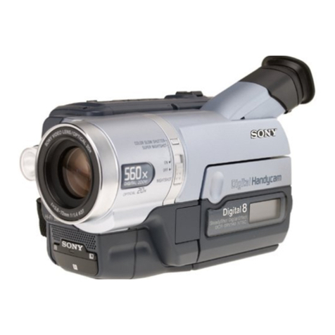
  9. Sony Handycam Vision CCD-TRV300E User manual

Sony Handycam Vision CCD-TRV300E User manual

Other manuals for Handycam Vision CCD-TRV300E

2

This manual suits for next models

1

Other Sony Camcorder manuals

Sony DSR-250 User manual

Sony

Sony DSR-250 User manual

Sony Handycam DCR-HC85E User manual

Sony

Sony Handycam DCR-HC85E User manual

Sony Handycam DCR-IP5 User manual

Sony

Sony Handycam DCR-IP5 User manual

Sony CCD-TRV30 - Video Camera Recorder 8mm User manual

Sony

Sony CCD-TRV30 - Video Camera Recorder 8mm User manual

Sony HANDYCAM PMW-320K User manual

Sony

Sony HANDYCAM PMW-320K User manual

Sony Handycam NEX-VG900E User manual

Sony

Sony Handycam NEX-VG900E User manual

Sony PXW-X320 User manual

Sony

Sony PXW-X320 User manual

Sony Handycam CCD-TR416 User manual

Sony

Sony Handycam CCD-TR416 User manual

Sony Handycam HDR-SR11E User manual

Sony

Sony Handycam HDR-SR11E User manual

Sony Handycam HDR-CX240 User manual

Sony

Sony Handycam HDR-CX240 User manual

Sony XDCAM PMW-160 User manual

Sony

Sony XDCAM PMW-160 User manual

Sony IPELA PCS-G70 User manual

Sony

Sony IPELA PCS-G70 User manual

Sony DCR-DVD610 User manual

Sony

Sony DCR-DVD610 User manual

Sony HXR-MC2000U User manual

Sony

Sony HXR-MC2000U User manual

Sony PXW-FX9V General instructions

Sony

Sony PXW-FX9V General instructions

Sony HDR-CX110 - High Definition Flash Memory Handycam... User manual

Sony

Sony HDR-CX110 - High Definition Flash Memory Handycam... User manual

Sony Handycam Vision DCR-TRV9 User manual

Sony

Sony Handycam Vision DCR-TRV9 User manual

Sony Handycam DCR-HC27E User manual

Sony

Sony Handycam DCR-HC27E User manual

Sony CFI-ZEY1 User manual

Sony

Sony CFI-ZEY1 User manual

Sony BRC-Z330 User manual

Sony

Sony BRC-Z330 User manual

Sony EVI-HD1 User manual

Sony

Sony EVI-HD1 User manual

Sony Handycam HDR-HC5E User manual

Sony

Sony Handycam HDR-HC5E User manual

Sony Handycam DCR-SR58E User manual

Sony

Sony Handycam DCR-SR58E User manual

Sony Handycam HDR-HC9 User manual

Sony

Sony Handycam HDR-HC9 User manual

Popular Camcorder manuals by other brands

Vivitar DVR 830XHD owner's manual

Vivitar

Vivitar DVR 830XHD owner's manual

Panasonic HX-WA20PP Service manual

Panasonic

Panasonic HX-WA20PP Service manual

Canon FS1 instruction manual

Canon

Canon FS1 instruction manual

Sharp VL-H400S Operation manual

Sharp

Sharp VL-H400S Operation manual

Panasonic AJ-D900WAP operating instructions

Panasonic

Panasonic AJ-D900WAP operating instructions

Samsung VP-D6550 Owner's instruction book

Samsung

Samsung VP-D6550 Owner's instruction book

Naxa NDC-402 instruction manual

Naxa

Naxa NDC-402 instruction manual

LG L320-BN owner's manual

LG

LG L320-BN owner's manual

Vivitar DVR 865HD user manual

Vivitar

Vivitar DVR 865HD user manual

Toshiba CAMILEO Z100 user guide

Toshiba

Toshiba CAMILEO Z100 user guide

Panasonic NV-VS40B operating instructions

Panasonic

Panasonic NV-VS40B operating instructions

Canon RC 260 instructions

Canon

Canon RC 260 instructions

Brinno TimeLapse TLC200 user manual

Brinno

Brinno TimeLapse TLC200 user manual

JVC GR-SXM68AC Schematic diagram

JVC

JVC GR-SXM68AC Schematic diagram

MYDLINK DCS-6100LH Quick installation guide

MYDLINK

MYDLINK DCS-6100LH Quick installation guide

SECURECOM V-5014B installation guide

SECURECOM

SECURECOM V-5014B installation guide

JVC AA-V15EG instruction manual

JVC

JVC AA-V15EG instruction manual

Canon LEGRIA HV40 instruction manual

Canon

Canon LEGRIA HV40 instruction manual

manuals.online logo
manuals.online logoBrands
  • About & Mission
  • Contact us
  • Privacy Policy
  • Terms and Conditions

Copyright 2025 Manuals.Online. All Rights Reserved.

Sony Corporation
CCD-TRV300ERMT-717
SERVICE MANUAL
CCD-TRV300E
RMT-717
SERVICE MANUAL
MICROFILM
For MECHANISM ADJUSTMENTS, refer to
the“8mmVideoMECHANICALADJUSTMENT
MANUAL VII” (9-973-801-11).
SPECIFICATIONS
HVIDEO CAMERA RECORDER
B MECHANISM
Sony Corporation
Personal A&V Products Company9-974-057-11
98C0941-1
Printed in Japan © 1998. 3
Published by Quality Engineering Dept.
(Osaki East)
– 266 –
CCD-TRV300E
AEP Model
CCD-TRV300E
• For printed wiring boards.
•b: Pattern from the side which enable seeing.
(The other layer's patterns are not indicated.)
• Circled numbers refer to waveforms.
• Through hole is omitted.
• There are few cases that the part printed on diagram isn’t
mounted in this model.
• Chip parts.
Transistor Diode
• For schematic diagrams.
• All capacitors are in µF unless otherwise noted. pF: µµF.
50Vorlessarenotindicatedexceptforelectrolyticsandtantalums.
• Chip resistor are 1/16W unless otherwise noted.
kΩ: 1000Ω, MΩ: 1000kΩ.
• Caution when replacing chip parts.
New parts must be attached after removal of chip.
Becarefulnottoheattheminussideoftantalumcapacitor,because
it is damaged by the heat.
• Some chip part will be indicated as follows.
Example C541 L452
22U 10UH
TA A 2520
• Constants of resistors, capasitors, ICs and etc with XX indicate
tha they are not used. In such cases, the unused circuits may be
indicated.
• Parts with differ according to the model/destination. Refer to
the mount table for each function.
• All variable and adjustable resistors have characteristic curve B,
unless otherwise noted.
• Signal name
XEDIT nEDIT PB/XREC nPB/REC
•2: non flammable resistor.
•1: fusible resistor.
•H: panel designation.
•A: B+ Line
•B: B– Line
•J: IN/OUT direction of (+, –) B LINE.
•C: adjustment for repair.
• Circled numbers refer to waveforms.
4-8 4-9
CD-200 (CCD IMAGER) PRINTED WIRING BOARD
– Ref No. CD-200 BOARD: 8,000 series –
CCD IMAGER
CD-200
Note on the CCD imager replacement
• The CCD imager is not mounted for the already mounted
CD-200 board supplied as the repair parts.
When replacing the CD-200 board, remove the CCD imager
from the old board and install on the new board.
• Perform all adjustments of the camera block when the CCD
imager has been replaced.
• Handle the CCD imager with attention such as MOS IC as it
may be broken by static electricity in the structure.
Also, prevent the receiving light section from dust attached
and strong light.
• For Printed Wiring Boards.
•Chip transistor
There are few cases that the part isn't mounted in this model is
printed on this diagram.
C
Q
BE
CD-200 BOARD
C401 A-3
C403 A-3
C405 A-3
C406 A-3
C407 B-3
CN401 B-3
IC401 A-1
L401 B-1
Q402 A-3
R401 A-3
R404 A-3
R405 A-3
4-2. PRINTED WIRING BOARDS AND SCHEMATIC DIAGRAMS
THIS NOTE IS COMMON FOR PRINTED WIRING BOARDS AND SCHEMATIC DIAGRAMS.
(In addition to this, the necessary note is printed in each block.)
• Measuring conditions voltage value and waveform.
• The object is color bar chart of pattern box.
• Voltages and dc between ground and measurement points.
Readings are taken with a digital multimeter (DC 10MΩ).
• Voltages variations may be noted due to normal production
tolerances.
1.Connection
2.Adjust the distance so that the output waveform of Fig. a and the
Fig. b can be obtain.
Fig. b (Picture on monitor TV)
Fig. a (Video output terminal output waveform)
Pattern box
1.5m
Kinds of capacitor
(
Â
External dimensions (mm)
Â
Temperature
chracteristics
The components identified by
mark !or dotted line with mark
!are critical for safety.
Replace only with part number
specified.
When indicating parts by refer-
encenumber,pleaseincludethe
board name.
4-7
Lens reference plane
surface lmaging surface
of CCD imager
(IC401 on CD-200 board)
Electron beam
scanned frame
CRT picture frame
Yellow
Cyan
Green
White
Magenta
Red
Blue
ABBA
A=B
H
Yellow
Cyan
Green
White
Magenta
Red
Blue
C
Q
BE
546
132
Q
564
312
Q
54
312
Q
21
Q
534
3
21
3
21
3
21
1234
A
B
09
CD-200 BOARD (SIDE B) CD-200 BOARD (SIDE A)
1-669-001- 11
1
2
3
CD-200 BOARD
CAMERA REC
H
7Vp-p
IC401 1 2
1
2
3
,
H
7Vp-p
IC401 3 4
H
1.3Vp-p
IC401 7
,
CD-200
(CCD IMAGER)
CF-54
(PANEL SWITCH)
MA-332
(STEREO MIC)
PJ-87
(
AV OUT
)
DD-105
(POWER)
CCD-TRV300E
4-16 4-17 4-18
CAMERA (1)
VC-195 (1/9)
CCD-TRV300E
VC-195 BOARD (1/9)
1
2
3
4
5
6
7
8
9
28.375 MHz
2.3Vp-p
IC501
CAMERA REC
5
14.18 MHz
2.3Vp-p
IC501
CAMERA REC
11 12,
H
7Vp-p
IC501 25
CAMERA REC
26,
H
7Vp-p
IC501 28
CAMERA REC
31,
H
3Vp-p
IC501 44
CAMERA REC
V
3Vp-p
IC501 45
CAMERA REC
3.2Vp-p
IC502 2 10
CAMERA REC
H
1.3Vp-p
IC502 26
CAMERA REC
H
0.4Vp-p
IC502 36
PB
—
0.14usec
CCD-TRV300E
4-19 4-20 4-21 4-22
CAMERA (2)
VC-195 (2/9)
• For schematic diagrams.
•Refer to page 4–11 for Printed Wiring Board.
CCD-TRV300E
CCD-TRV300E
4-24 4-25 4-26
4-23
Y/C PROCESSOR
VC-195 (3/9)
• For schematic diagrams.
•Refer to page 4–11 for Printed Wiring Board.
VC-195 BOARD (3/9)
10 20
21
22
23
24
25
26
27
28
29
11
12
13
14
15
16
17
18
19
H
0.34Vp-p
IC202 3
CAMERA REC
H
0.84Vp-p
IC202 6
CAMERA REC
4V
3Vp-p
IC202 71
CAMERA REC
2V
3Vp-p
IC202 72
CAMERA REC
V
3Vp-p
IC202 81
CAMERA REC
3.2Vp-p
IC201 8
CAMERA REC
H
3Vp-p
IC202 80
PB
H
0.5Vp-p
IC202 13
CAMERA REC
H
0.4Vp-p
IC202 16
CAMERA REC
H
0.18Vp-p
IC202 23
CAMERA REC
H
0.18Vp-p
IC202 26
CAMERA REC
H
0.9Vp-p
IC202 33
CAMERA REC
V
0.4Vp-p
IC202 40
PB
V
3Vp-p
IC202 60
CAMERA REC
H
3Vp-p
IC202 61
CAMERA REC
IC202 66
4.43 MHz
3.1Vp-p
CAMERA REC
7.16 MHz
V
3Vp-p
IC201 19
CAMERA REC
H
3Vp-p
IC201 20
CAMERA REC
0.14usec
3.5Vp-p
IC204 12 15
CAMERA REC
—
3.5Vp-p
IC204 23 30
CAMERA REC
—
0.14usec
CCD-TRV300E
4-27 4-28 4-29 4-30
IN/OUT
VC-195 (4/9)
• For schematic diagrams.
•Refer to page 4–11 for Printed Wiring Board.
CCD-TRV300E
VC-195 BOARD (4/9)
CAMERA REC
H
0.46Vp-p
IC151 3
H
0.32Vp-p
IC151 5
30
31
32
33
34
H
IC151 29
IC151 62
(2.1Vp-p)
(1.6Vp-p)
H
1.4Vp-p
IC151 17 64
,
H
1.8Vp-p
IC151 25 60
,
CCD-TRV300E
4-31 4-32 4-33 4-34
• For schematic diagrams.
•Refer to page 4–11 for Printed Wiring Board.
REC/PB HEAD AMP
VC-195 (5/9)
VC-195 BOARD (5/9)
2V
0.3Vp-p
IC001 TRIG :IC001
5 21
35
36
37
38
39
40
41
42
43
44
H
0.3Vp-p
IC001 3
CAMERA REC
CAMERA REC
H
0.4Vp-p
IC001 7
PB
V
0.4Vp-p
IC001 11
PB
V
0.4Vp-p
IC001 17
PB
2V
2.9Vp-p
IC001 21
CAMERA REC
2V
3Vp-p
IC001 44 48
CAMERA REC
,
V
0.18Vp-p
IC001 61
CAMERA REC
V
3Vp-p
IC001 62
CAMERA REC
45
7Vp-p
Q001 C
CAMERA REC
H
3Vp-p
IC701 16
CAMERA REC
4.12 MHz
CCD-TRV300E
4-37
• For schematic diagrams.
•Refer to page 4–11 for Printed Wiring Board.
SERVO/SYSTEM CONTROL
VC-195 (6/9)
4-35 4-36
VC-195 BOARD (6/9)
CAMERA REC
2V
3Vp-p
IC402
47
4V
3Vp-p
IC402
48
2V
3Vp-p
IC402
55 57
3Vp-p
IC402
68
13usec
3Vp-p
IC402
69
13usec
3Vp-p
IC402
70
46
47
48
49
50
51
52
53
54
55
IC402
1
20 MHz
1.7Vp-p
1.2msec
3Vp-p
IC402
115
2.8msec
3Vp-p
IC402
116
2V
3Vp-p
IC402
117
,
13usec
CCD-TRV300E
• For schematic diagrams. • Refer to page 4–11 for Printed Wiring Board.
SERVO
VC-195 (7/9)
4-39
4-38 4-40
CCD-TRV300E
4-41 4-42 4-43 4-44
AUDIO
VC-195 (8/9)
• For schematic diagrams.
•Refer to page 4–11 for Printed Wiring Board.
CCD-TRV300E
VC-195 BOARD (8/9)
59
60
61
62
IC301 32
4.43 MHz
0.26Vp-p
2V
2.9Vp-p
IC301 21
CAMERA REC
V
0.4Vp-p
IC301 24
PB
V
0.36Vp-p
IC301 29
CAMERA REC
CAMERA REC
VC-195 BOARD (7/9)
CAMERA REC
2V
3Vp-p
IC451 11
2.8msec
3Vp-p
IC451 18
5.6msec
1.2Vp-p
IC451 1 2 29
56
57
58
,,