manuals.online logo
Brands
  1. Home
  2. •
  3. Brands
  4. •
  5. Sony
  6. •
  7. CD Player
  8. •
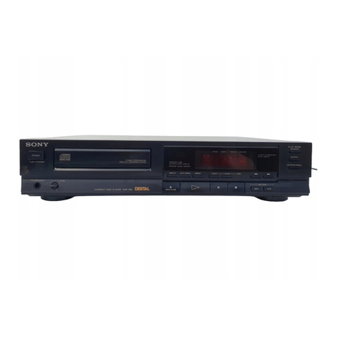
  9. Sony CDP-70 User manual

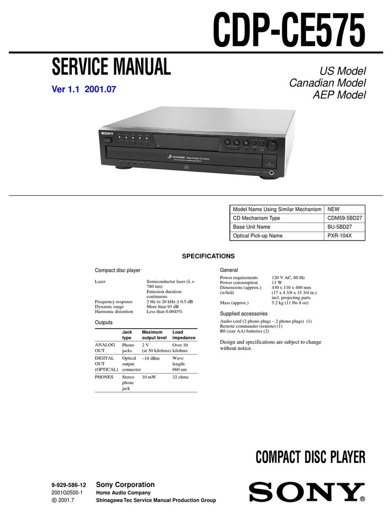
Sony CDP-70 User manual

SERVICE
MANUAL
US
Model
Canadian
Model
AEP
Model
UK
Model
E
Model
SPECIFICATIONS
Output
level
2
V
(at
50
kiloohms)
Load
impedance
over
10
kiloohms
Compact
disc
player
Compact
disc
digital
audio
system
Laser
output
Max.
44.6
pW"
*
This
output
is
the
value
measured
at
a
distance
of
about
200
mm
from
the
Pick-up
Block.
Frequency
response
|
2Hz-
20,000
Hz
(+0.3
dB)
Signal-to-noise
ratio
{|More
than
102
dB
Channel
separation
More
than
98
dB
(1kHz)
Outputs
LINE
OUT
(phono
jacks)
DIGITAL
OUT
(OPTICAL)
|
Wave
fength
660
nm
(optical
output
connector)
|
Output
level
-
18
dBm
HEADPHONES
Output
level
max.
15
mW
(stereo
phono
jack)
Load
Impedance
32
ohms
Dimensions
(approx.)
Laser
Semiconductor
laser
(A
=
780
nm)
Emission
duration:
continuous
objective
lens
surface
on
the
Optical
Dynamic
range
More
than
95
dB
Harmonic
distortion
Less
than
0.003%
(1kHz)
(Fixed)
General
(w/h/d)
120
V
AC,
60Hz
430
x
95
x
275
mm
(17
x
3%
x
10%
inches)
including
projecting
parts
and
controls
Weight
(approx.,
net)
|3.5
kg
(7
Ibs
11
02)
MICROFILM
Model
Name
Using
Similar
Mechanism)
CDP-208ESD
CD
Transport
Mechanism
Type
KSS-150A(RP)
Optical
Pick-Up
Block
Type
BU-5C
Supplied
accessories
Audio
signal
connecting
cord
1
(2
phono
plugs
-
2
phono
plugs)
Remote
commander
|
tT
Sony
SUM-3
(NS)
batteries
Remote
commander
Remote
control
Infrared
control
system
3
V
DC
with
two
size
AA
(Ré)
batteries
67
x
20
Xx
175
mm
(w/h/d)
(2%
x
13/16
X
7
inches)
Weight
135
g
(5
oz)
including
batteries
Design
and
specifications
subject
to
change
without
notice.
SAFETY-RELATED
COMPONENT
WARNING!!
COMPONENTS
IDENTIFIED
BY
MARK
A
OR
DOTTED
LINE
WITH
MARK
A
ON
THE
SCHEMATIC
DIAGRAMS
AND
IN
THE
PARTS
LIST
ARE
CRITICAL
TO
SAFE
OPERATION.
REPLACE
THESE
COMPONENTS
WITH
SONY
PARTS
WHOSE
PART
NUMBERS
APPEAR
AS
SHOWN
IN
THIS
MANUAL
OR
IN
SUPPLEMENTS
PUB-
LISHED
BY
SONY.
COMPACT
DISC
PLAYER
SONY.
Pe
Ree
Te
ee
ee
ae
ee
~
CDP-770
|
TABLE
OF
CONTENTS
Section
Title
SECTION
1
GENERAL
1-1.
Location
of
Controls
................
220
e
eens
SECTION
2
ELECTRICAL
ADJUSTMENTS
............
SECTION
3
DIAGRAMS
3-1.
Semiconductor
Lead
Layouts
..................
3-2.
Printed
wiring
Boards.................-02.
eee
3-3.
Schematic
Diagram
...........
0...
c
cess
eee eee
SAFETY
CHECK-OUT
After
correcting
the
original
service
problem,
perform
the
following
safety
check
before
releasing
the
set
to
the
customer:
Check
the
antenna
terminals,
metal
trim,
“metallized”
knobs,
screws,
and
all
other
exposed
metal
parts
for
AC
leakage.
Check
leakage
as
described
below.
LEAKAGE
TEST
The
AC
leakage
from
any
exposed
metal
part
to
earth
ground
and
from
all
exposed
metal
parts
to
any
exposed
metal
part
having
a
return
to
chassis,
must
not
exceed
0.5mA
(500
microampers).
Leakage
current
can
be
measured
by
any
one
of
three
methods.
1.
A
commercial
leakage
tester,
such
as
the
Simpson
229
or
RCA
WT-S40A._
Follow
the
manufacturers’
instructions
to
use
these
instru-
ments.
to
A
battery-operated
AC
milliammeter.
The
Data
Precision
245
digital
multimeter
is
suitable
for
this
job.
e
iy
Section
Title
3-4.
Explanation
of
IC601
(MSC6458-36SS)
..........
3-4-1...
Pin:
Descriptions
biases
iG
ee
dias
ogee
ee
3-5.
IC
Block
Diagrams
...............
0.
cece
eee
eee
SECTION
4
EXPLODED
VIEWS
A-\:.
Main
Block
ics
csa3
cae
een
es
Cte
Pad
MAAS
4-2.
Optical
Pick-Up
Block
..................0.000.
11
|
SECTION
5
ELECTRICAL
PARTS
LIST
................
3.
Measuring
the
voltage
drop
across
a
resistor
by
means
of
a
VOM
or
battery-operated
AC
volt-
meter.
The
“‘limit”
indication
is
0.75
V,
so
analog
meters
must
have
an
accurate
low-
voltage
scale.
The
Simpson
250
and
Sanwa
SH-63Trd
are
examples
of
a
passive
VOM
that
is
suitable.
Nearly
all
battery
operated
digital
multimeters
that
have
a
2V
AC
range
are
suitable.
(See
Fig.
A}
To
Exposed
Metal
Parts
on
Set
|
AC
voltmeter
(0.75
V)
0.15uF
T
1.542
=
Earth
Ground
Fig.
A.
Using
an
AC
voltmeter
to
check
AC
leakage.
SERVICING
NOTE
NOTES
ON
HANDLING
THE
OPTICAL
PICK-
UP
BLOCK
OR
BASE
UNIT
The
laser
diode
in
the
optical
pick-up
block
may
suffer
electrostatic
breakdown
because
of
the
poten-
tial
difference
generated
by
the
charged
electrostatic
load,
etc.
on
clothing
and
the
human
body.
During
repair,
pay
attention
to
electrostatic
break-
down
and
also
use
the
procedure
in
the
printed
matter
which
is
included
in
the
repair
parts.
The
flexible
board
is
easily
damaged
and
should
be
handled
with
care.
CAUTION
Use
of
controls
or
adjustments
or
performance
of
procedures
other
than
those
specified
herein
may
result
in
hazardous
radiation
exposure.
NOTES
ON
LASER
DIODE
EMISSION
CHECK
The
laser
beam
on
this
model
is
concentrated
so as
to
be
focused
on
the
disc
reflective
surface
by
the
objective
lens
in
the
optical
pick-up
block.
Therefore,
when
check-
ing
the
laser
diode
emission,
observe
from
more
than
30
cm
away
from
the
objective
lens.
—2—
|
CDP-770
SECTION
1
GENERAL
1-1.
LOCATION
OF
CONTROLS
Front
Panel
.
Remote
Commander
oe
GLEAR/REPEAT
(A<>B
clear/repeat)
button
20
<<>>
SLOW
(Low
i
speed
manual
search)
9
buttons
18}
A<->B
repeat
button
POWER
switch
re
This
indicates
a
function
available
Disc
compartment
only
on
the
main
unit.
hail
button
“|
This
indicates
a
function
available
EMOTE
sensor
E
only
on
the
remote
commander.
FADER
(FADE
IN/FADE
OUT)
button
EDIT/TIME
FADE
button
CHECK
(program
check)
button
CLEAR
(program
clear)
button
<<>>
(manual
search)
buttons
PROGRAM
or
PGM
button
SHUFFLE
button
Numeric
buttons
HEADPHONE
VOL
control
PHONES
jack
>
20
(over
20)
button
CONTINUE/SINGLE
button
k44
>i
(AMS*)
buttons
@
(stop)
button
Il
(pause)
button
P
(play)
button
&
(open/close)
button
AUTO
SPACE
button
TIME
button
SSPE
SeReNESOONoFAeNE)
*AMS
is
the
abbreviation
of
Automatic
Music
Sensor.
CDP-770
SECTION
2
ELECTRICAL
ADJUSTMENTS
1.
Perform
adjustments
in
the
order
given.
1.
Connect
oscilloscope
to
test
point
TP
(RF)
and
TP
(RFG),
2.
Use
YEDS-18
(Part
No:
3-702-101-01)
disc
unless
other-
2.
Turn
POWER
switch
on.
wise
indicated.
3.
Put
disc
(YEDS-18)
in
and
press
DP
button.
3.
Use
the
oscilloscope
with
more
than
10
MQ
impedance.
4.
Adjust
RV102
for
an
optimum
waveform
eye
pattern
or
so
that
the
peak
is
maximum.
Optimum
eye
pattern
means
RF
PLL
Frequency
Adjustment/Lock
Frequency
Check
that
shape
“©”
can
be
clearly
distinguished
at
the
center
Procedure
:
of
the
waveform.
frequency
counter
RF
signal
waveform
main
board
\
KAKA
|
ee
pe
ANY
a
XA
.
Connect
test
point
TP
(ASY)
to
ground
with
lead
wire.
XXX
AA
2.
Tum
POWER
switch
on.
NUN
3.
Connect
the
frequency
counter
to
test
point
TP
(PCK)
pene
a
and
TP
(AG).
reo
wr
4.
Adjust
RV201
so
that
the
reading
on
the
frequency
counter
is
43218MHz+30kHz.....
(RF
PLL
frequency
adjustment).
5.
Remove
lead
wire
connecting
TP
(ASY)
to
ground.
Adjustment
Location:
main
board
6.
Put
disc
(YEDS-18)
in
and
press
>
button.
7.
Confirm
that
the
reading
on
frequency
counter
is
4.3218MHz.....
(Lock
frequency
check).
E-F
Balance
Adjustment
eee
:
:
EF
TEO
This
adjustment
should
be
made
when
replacing
TOP
(T
eatance
{
TE!
type
Optical
Pick-up).
ADJ
RV101
Procedure
:
oscilloscope
(DC
range)
it
FOCUS
RF
BIAS
RFG
AG
RF
PLL
ADJ
\RV102
PCK
FREQUENCY
,
ADJ/LOCK
‘d
main
boar
ere
FREQUENCY
TP
(TEO)
Om———-O
+
CHECK
TP
(AG)
Om—_——-0
~
1.
Connect
test
point
TP
(ADJ)
and
test
point
TP
(TEI)
to
ground
with
lead
wire.
Connect
oscilloscope
to
test
point
TP
(TEO)
and
TP
(AG).
Turn
POWER
switch
on.
Put
disc
(YEDS-18)
in
and
press
>
button.
Adjust
RV101
so
that
the
traverse
waveform
is
symmetri-
cal
above
and
below.
6.
After
adjustment,
remove
the
lead
wire
connected
in
step
5.
VF
wp
A=B
A
(within
5%)
Bg
VOLT/DIV:
IV
TIME
/DIV:
Ims
Focus
Bias
Adjustment
This
adjustment
should
be
made
when
replacing
TOP
(T-
type
Optical
Pick-up).
Procedure:
oscilloscope
(DC
range)
main
board
Cc
a
TP
(RF)
O«———O
+
TP
(RFG)O—m——_—oO
—
REFERENCE
1.
Focus/Tracking
Gain
Adjustments
A
frequency
responce
analyzer
is
necessary
in
order
to
perform
this
adjustment
exactly.
However,
this
gain
has
a
margin,
so
even
if
it
is
slightly
off,
2,
there
is
no
problem.
Therefore,
do
not
perform
this
adjust-
ment.
3.
Focus/tracking
gain
determines
the
pick-up
follow
up
(verti-
4.
cal
and
horizontal)
relative
to
mechanical
noise
and
shock
when
the
2-axis
device
operate.
:
However,
as
these
reciprocate,
the
adjustment
is
at
the
point
where
both
are
satisfied.
@
When
gain
is
raised,
the
noise
when
the
2-axis
device
oper-
ates
increases.
@When
gain
is
lowered,
mechanical
shock
and
skipping
occurs
more
easily.
@
When
gain
adjustment
is
off,
the
symptoms
below
appear.
Symptoms
Tracking
eThe
time
until
music
starts
becomes
longer
for
@
—
D
or
automatic
é
l
.
ed
selection.
(Kid,
DD
but-
Onion.
teh
tons
pressed.)
(Normally
takes
about
1
seconds.)
@
Music
does
not
start
and
disc
continues
to
rotate
for
@
—
DP
or
automatic
selection.
(Ki<J,
DEI
buttons
pressed.)
@Disc
table
opens
shortly
after
aS
be.
low
or
high
Sound
is
interrupted
dur-
ing
PLAY
or
time
counter
display
stops
progressing.
®
More
noise
during
2-axis
device
operation.
The
following
is
a
simple
adjustment
method.
—Primary
Adjustment
—
Note
:
Since
exact
adjustment
cannot
be
performed,
remem-
ber
the
positions
of
the
controls
before
performing
the
adjustment.
If
the
position
after
the
primary
adjust-
ment
are
only
a
little
different,
return
the
controls
to
the
original
position.
Procedure
:
oscilloscope
(DC
range)
main
board
C)
TP
(FEO)
soar
emea
+
|
TP
(TEO)
O=e-
-7
|
O-
Keep
the
set
horizontal.
If
the
set
is
not
horizontal,
this
adjustment
cannot
be
performed
due
to
the
gravity
against
the
2-axis
device.
Insert
disc
(YEDS-18:
Fifth
Selection)
and
press
>
but-
ton.
Connect
oscilloscope
to
main
board
TP
(FEO).
Adjust
RV103
so
that
the
waveform
is
as
shown
in
the
figure
below.
(focus
gain
adjustment)
Connect
oscilloscope
to
main
board
TP
(TEO).
Adjust
RV104
so
that
the
waveform
is
as
shown
in
the
figure
below.
(tracking
gain
adjustment)
VOLT
/DIV
:
100mV
TIME
/DIV
:
2mS
100mV
ov
@
Incorrent
Examples
(DC
level
changes
more
than
on
adjust-
waveform)
low
focus
gain
VOLT/DIV:
100mV
TIME
/DIV
:
2mS
250mV
ov
high
focus
gain
VOLT/DIV:
100mV
TIME/DIV
:
2mS
100mV
75mV
OV
ov
@
Incorrect
Examples
(fundamental
wave
appears)
low
tracking
gain
TIME
/DIV
ov
high
tracking
gain
higher
fundamental
wave
than
for
low
gain)
ov
Adjustment
Location
:
main
board
VOLT
/DIV:
TIME
/DIV
:
VOLT/DIV
:
VOLT/DIV
:
TIME
/DIV
:
Iv
2ms
lV
:
2ms
IV
2ms
VOLT/DIV:
IV
TIME
/DIV
:
2mS
ov
Incorrect
Examples
(fundamental
wave
appears)
low
tracking
gain
VOLT/DIV:
IV
TIME
/DIV
:
2mS
OV
high
tracking
gain
higher
fundamental
wave
than
for
low
gain)
VOLT/DIV:
1V
TIME
/DIV
:
2mS
ov
Adjustment
Location:
main
board
FEO
FOCUS
rvio3
{
GAIN
ADJ
Feat
TRACKING
TEO
L.-.
Gan
RV104
ADJ
SECTION
3
DIAGRAMS
3-1.
SEMICONDUCTOR
LEAD
LAYOUTS
CXA1081S
GP1F31T
M5231TL
vr3ses
CXA1082BS
GP1U52
M5294P
PCMS56P-S
16
1514131211109
12345678
(Top
view)
CXA1291P
LC9600P-144
NJM4556S
t234se7as
MSC6458-36SS
CXD1125Q
DTA144ES
DTC114ES
DTC143TS
DTC144ES
(Top
view)
MARKING
SIOE
VIEW
ae
CxD2550P
M5218P
DTC114EF
M74HC6004P
1g 10
=
al
~
/
;
(Top
view)
?
(Top
view)
2
\
CDP-770
BR4361F
™~
cathode
anode
HZS9B2L
RD5.1ESB2
18$132
cathode
anode
US1060M
10E2
cathode
anode
e@
Semicouductor
Location
[rete
[boston]
@
oO——:
parts
extracted
from
the
component
side.
e
:
Jumper
wire
connected
to
the
ground
pattern
on
the
component
side.
3-2.
PRINTED
WIRING
BOARDS
e
Refer
to
page7
for
Semiconductor
Lead
Layouts.
a
ae
ee
ea
a
5
[7
[|
8
[|
9
[|
©
[|
"1
[|
v2
[|
8
[
4
|
R
fine
car
doo
ee
EXCEPT
FOR
aoe
ee
—
A
[MAIN
BOARD]
|
°33ti.f27
‘gee
ae
VOLTAGE
SELECTOR
US
MODEL
EXCEPT
FOR
\
=
B
(aS
asd
UK
MODEL
|
C
|]
*anstarSaekehuen
|
|
|
Saale:
—
EEPEES
Py
ae
—
=
aie
D
L
;
-
;
:
|
1
|
|
Sl
(CHASSIS)
ie
_
ea
T
|
.
|
[
IN/OUT
SWITCH
BOARD
}
!
[LOADING
MOTOR
BOARD
]
|
!
j
!
‘
i}
US
MODEL
$704
:
iy
:
IN/OUT
SW
i
is
dl
L-
G
eee
im
Pa
eae
$éa6
sey
|
REPEAT
_
[FADER]
[EDIT/T
IME
FADI
-—
2
‘e's
eee
2%
&
of}
{POWER
SWITCH
BOARD]
ExCeL
OR
:
ya
EXCEPT
FOR
\
us
ars
aR
a
US
MODEL
MODEL
ae
_—
7
55/58
K
to
page7
for
Semiconductor
Lead
Layouts.
ae
eee
a
ee
ee,
9
|
0
|
ft
[19
=|
20
=|
21
22
EXCEPT
FOR
5001
c
a
VOLTAGE
SELECTOR
y=1
EXCEPT
FOR
UK
MODEL
aan
|
fed
—
at
AC
IN
[my
es
PS
fo
|
po
AC
IN
ea
eee
UK
MODEL
US
MODEL
(WHT
(GRY)
{REO
MI
GRY))
WHT
wo
TRED
BLK
BLK
WHT
|
RED
BLU
WHT
RED
%
NOT
REPLACEABLE.
BUILT
IN
TRANSFORMER
(CHASSIS)
<3
>—
EXCEPT
FOR
US
MODEL
<i>
X
EXCEPT
FOR
x
US
US
MODEL MODEL
{IN/OUT
SWITCH
BOARD
J
[LOADING
MOTOR
BOARD
}
$701
IN/OUT
SW
{DISPLAY
BOARD]
[POWER
SWITCH
BOARD]
EXCEPT
FOR
1,
(Rua
Space]
5
)_SPAC:
OPTICAL
PICK
UP
BLOCK(KSS~150A(RP)
([SL/SP
MOTOR
BOARD]
i
aS
Q.
$101
:
LIMIT
IN
SW
is]
toe
5
a
“30
“3
%
9
9
9
0%
oO
OG
aoa
0602:c601
S61
Ge
go)
e209
oH.
_
|
EXCEPT
FOR
eee"
US
MODEL
of
WHT.
BE]
a
pie
|
$605
OR
POWER
SWITCH
EXCEPT
FOR
US
MODEL
BOARD
{MOTOR
BOARD
hes
MOTOR
BOARD
[ENZ00r
SWITCH
BOARD
[er
SI
ee
|
LGaD
NG
1 7
|
sig
25640.)
MOTOR
Pq
S701
IN/OUT
SW.
STANDBY
[]
OmM2
He
1
ial
1
——
ENF
BON
EXCEPT
FOR
7
US
MODEL
CNP602
DR
i
[DISPLAY
BOARD
]
ee
alee
Dae
Oe
eee
ee
a
ey
ee
|_exP208
FLD601
FLUORESCENT
INDICATOR
TUBE
camo
bs
eke
bbe
Ebb
Etbt
1234
«5
ie
ead
a
st
in ee
EE}
ERR
ERE,
ERED
STEP
>
[ll]
AUTO.
EDIT
«44
49
1C202
VIDEO
SPACE
TIME
I
SLED
MOTOR/
PROGRAM
|
Part
FOCUS
COIL/
FADE)
16
17
Hee
SHUFFLE
REPEAT
us
wong.
|
colL
DRIVE
[p>
=]
:
SINGLE
1
|
|
;
R222
R218
|
R20
D608
150k
6.
8k
3’
7k
1a
HZS9BILT2
ch
0
—w-4+
fH
z
et
vad
mane
x
|
eli
@601-603
Te]
a
\
DIGIT DRIVE
I
LOAD
I
NG/VOL
_=*
MOTOR
DRIVE
0
|
|
ial
I
|
|
MASTER
CONTROL
|
|
|
!
|
|
i
Ov
|
DISC
TABLE
f)
ty
uscedee-36ss
Mik:
OTR
CLOSED:
4.
av
RESET
@ND
0(4)
TEST
(1)
ov
I
RO
ee
@
"OPEN
EBy
(36)
VL
UP
TOAD
IN
—
I
0.2
G7)
TIMER
LOAD
OUT
(38)
VL
LAMP
OUT
SW
:
5
@9)
8a
TD
ON
C1)
(1)
2
a
Comme
mn
es
Cumct
Pt
TT
[Sas
ey
rj
__
Pe
Lae
KEY
Gg
aE
_
><
hc]
EAP
3 3
4
rs
rac
Cnmmmne
——s
eo
e
e
EH
(41)
(9)
(10)
Ag
a
18
[>
><]
Hees
=
PEs@
fo}
——${r
et
><]
><]
es
STS
ee
aaa
«ee
(eeeemeaees
FET
4
rif
a
or
ae
ERERD
Er,
|
vr
AD
FC
SCOR
INVERTER
iN
{ttt
tf
G5)
scorn
sd
¥
SERRE,
‘Ons
<j
LTT
yt
|
fe
sys
©
@
735
484
@
@
HH
(59)
SYNC
OUT
a
(25)
18.5
><]
><]
i
R239
1k
3
Lee
4 4
arse
eX
PRG
L
>
(62)
PRG
D/DATA
(3)
aA
i
(a
ae
PRG
CK
+
|
|_|
(6)
Bra
ticrene
|
PRG.
CK/CLK
|
bat
—__
Pa
R236
ik
sie
ae
GET,
en
a
ee;
CNP204
0601-607
US1060M
l
i]
&
gl
sisi
sis
EXCEPT
|
S| 3} 8]
8
TIME
REPEAT
BD
_
FOR
US
ZA
tn)
oh
——)
MODEL
oO oO
oO
Oo
O@
$634
3635
$636 $637
L___
“STH
tO
Worl
¢
>
sao
[We],
[>>]
|
>|
—)
34
=a
1C602
!
!
33k
ita
L
[Boos
$629
[Besd
seit
[sex2
3633
GP1US2
|
[=)__|
BF
R605
—S
—
i)
=)
—S
33K
$623
[Buk
8628?
$626
['se27
|
FADER
a
4
“
REMOCON
goa
a
=o
sb
DETECTOR
l I
$617 $618
$619
$620
[se2i
$622
|
:
(520)
rs]
7
[8]
[3]
ain
=
rn
eal
a
a5
aa
Oo
Oo Oo Oo
ro.
oO
Oo Oo
Oo Oo
O
_
S611
$612 3613
$614
$615
$616
YS——————____——
i]
[12]
aos
=
aS
a a
=
oS
I I
33K
oe
O
ro
Oo
o
Of
oO
oO
4
J8«os
[B08
$607
$608
$609 $610
|
|
19
——_—_"—-—_—_—-
-
eo"
agai
=
ao
=
oo
ro
0
oH
O
33k
4
J
seal
$602
$603
$604
EDIT/TIME
FADE
1
44
BW
ITCH
SL/SP
MOTOR
BOARD
[
BOARD
|
r—
$701
=
wy
RSS,
RA
IN/OUT
SW.
S101
wio1
w102
LIMIT
IN
SLED
SPINDLE
TRACKING
FOCUS
LASER
OPT
l
CAL
P
l
CK
UP
.
WOTOR MOTOR
DETECTOR
=
git
git,
||
(tee
BE
BLOCK
(KSS-150A
(RP))
CEPT
F
de
' '
rie
MODEL
1
del
if
A
;
|
‘
|
-——__
-
——__-
(REeEEET
|
eceame
is
Bl
1
|
a
-
1
eer
-
——__
-
——__
-
Pepe
ee
shee
—
|
enez03
eealie
CNP202 CNP102
|
C105
108
enone
SLED
MOTOR/
FOCUS
COIL/
TRACKING
—————
ee
ROO4
10k
D006
RDS.
1ES
|
I
|
US
MODEL
COIL
DRIVE
0
|
a00t
SWITCHING
ae
2
s
:
3
D608
5
HZS9BILT2
oy
=)
=e
0
.
|
[pe
te
ROB
Aig?
RIo9
e
18k
4.7K
18k
+
se
a
FOR
US
aed
Te]
1C203]|
|wovev
Yon
cus
R110
ry
!
LOAD
ING/VOL
470007
4.
7k
rT
MOTOR
DRIVE
0
I
(J
O
g
s
=
3
=|
FOCUS/TRACKING/SLED/SP
|
NDLE
|
i
H
S
SERVO
I
8
3
1
>
S|
=
a
=z
I
—
RST
I
O
Q201,
202
PLL
SWITCHING
cer
[e305]
RESET
py
ry
VL_DOWN
o
o
INVERTER
VLUP
$
M3
5)
LOAD
IN
P79
bs
a
o§2"
Foy
tL
|
Loab
out
Pe
bs
:
7
Gn
L
2
OUT
SW
5
eS
cas
+
Lb
on
bX
i
ay
1008
10V
T
TN
SW
o
oe
><]
>~<]
o
(is)
7
R320
Y>-~<]
P<]
2.3
330
©
oO
8
©
©
2.3
My
(20)
2.5
[
secon
HY
23
rae
©
@
x
2
|
2.2
_—_
2
ne:
as)
a,
c90s
cage
Boxy
Hye.
2
A
@ ®
{R239
tk
7
g
StH
2.4
<
|
2]
@
@
we
8
necsal
ie
gal
PRG.
D/DATA
@
@
[_R237
1k
esi
5
“vo
|
tn”
(24) (29)
PRG
CK
DIGITAL
SIGNAL
a]
as
bane
PRG.
CK/CLK
Pe
©
R236
1k
pat
fet
—b0
PROCESSOR
@)
()——e
RICH]:
PLL
SW
P<
b<
er
|
on
eae
ols
oN
c
NP204
-~
Ls
.
2.5
100k
F——
3.2
0
R300
10k
=
ee
5
wa
od
:
!
i}
F304,
303
=
=
Sov
+
0.01
TF
R305
100K
or)
BS
=
Sal
aes
—___|_R304
100k
R303
10K
|
a>
—v
R302
22k
O
O
fi
|
fs
O
fost
1C30
I
l
i=
Lo
97
ane
DIGITAL
F
HT
tame
8
SSS
pw
4
> a
wid
ae
Ses
sofia,
ae
Peace
= =
aed
302
0.0334
CEOS
19)
TB
TIN
TENTS
TINTING)
H
SV
C315
LT
3
eae
|
rip
PHONE
LEVEL
=a
!
I
|
|
cee
ang
gee
|
10k/10k
|
ae
KNOB
POINT
INDICATOR
SaONET
ANE
co
Get
ree
L
EXCEPT
FOR
US
MODEL
ce
=13>
K
UP
DETECTOR
SOA
(RP))
=
t '
fe)
—_aanae
eee
ee
Oe
———_CNPIOI
CNPOO!
~|
DR
Qoo1
SWITCHING
‘3
o
SS
3
i=)
3
1c001
+/-SV
REG
IC1O1
CXA1081S
FOCUS
BIAS)
_-
y
02
R109
kK
18k
+
R108
RV
cz
cig
Sta:
cust
RIO
47k
EXCEPT
FOR
UK
MODEL
soot
VOLTAGE
SELECTOR
he-E
MODEL
OCUS/TRACK
|NG/SLED/SP
|
NDLE
SERVO
INVERTER
C313
100u
10V
A
ESS
|
2
oy
bg
3
5 §
Sece
Paes
WHER
Vn
en
cos
os
OO
an
aN
RRNN
AN
WO
UW
DY
wor
¥
170
woz
&
a
A03
8
1/0
|
aos
&
su
AOS
&
I
woe
S
At
ont
A
a
Ae
C308
22%
25V
D/A
CONVERTER
Hy
yp
2
MUTE
1C304
DIGITAL
FILTER
te
D401
18S132T-73
te
10402
D/A
CONVERTER
4.6
(.?)
ar
in
RS
MUTING SWITCH
MUTING
SWITCH
cNP4O1
|
Te}
a
|
L-CH
|
o
i
DIGITAL
AMP
a
wan
ines
i
US
MODEL}
cna
Pate
ei
Pr
i
:
L.
pa
is
Re
VL-cH
|
EC
ae
|
ee)
re
401,
402
(je
ears
Q407,
408
habe
VR-CH
MUT
ING
560
\
i
EXCEPT
FOR
Sn
LINE
OUT
FIXED
2
B
B
40)
4.6
L
R402 R404
10
30K
|
NAT
AOS
680
680
|
“ie
4
>
ow
Mop
(406 R408
R4IO}
C408
0.0068
0
a
oat
220
=
=220
eee
ay
AVE
ps.
=
=
C415
1C403
M5218P
1000p
9403
0 2SA1365
A)
a403
RVSO!
R502
Befoe
|
33K
D501
BR4361F
KNOB
POINT
INDICATOR
PHONE
AMP
wee
PHONE
AMP
EXCEPT
FOR
US
MODEL
US
MODEL
(ee
{
JACK
BOARD]
Pane
LeveL
a
J501
e
WAVE!
e
Allc
50W\
and
t.
e
All
r
speci
Voltz
unde
no
r
e
Volt
Volt
tion
e@
Wave
Volt
tion
e
Circl
e
Sign
cnegot
nies
ate
lt
oe
ee
ee
Se
1
UK
MODEL
a
ees
a
AC
IN
|!
SSO
]
St
ees
|
Ty
AC
IN
|
[2
Ee
eee
Nak
ue
ea
ly
EXCEPT
FOR
|
UK
MODEL
|
|
!
!
Q001
2SK381-TP
|
|
|
|
:
!
i
u |
|
|
|
|
\
VOLTAGE
|
SELECTOR
|
€
MODEL
220-240V=-110-120v!
re
(4)
fe
i
Moe
eeneae
en
re
vemn
|
|
%
NOT
REPLACEABLE
:
BUILT
IN
TRANSFORMER.
:
(1)
1C304
cr
——X)
balls
e
WAVEFORMS
Ole
10304
QP1F3!T
CNP4O!
|
Te]
Aaa
L.
i
:
DIGITAL
AMP
|
4
‘
wai
|
140y
SEC
R-CH
D/A
CONVERTER
TL
capa
et
—-}o
Bi
PLAY:
100"
Tov
are
|
atuaet
EL
retard
rn
evat
eaMteryaal
Elta.
A
i
ex
TEL
EMU
REET
MAES:
ov
1092
4ov
|
L=CH
A
CHa
APPROX.
100mVp-p
Nreseerace
Q401,
402
o
abn
Q407,
408
F
byte
VR-CH
MUT
ING
S60
|
Se
ec
ecu
uN
US
MOPEL
C405
=
22
.
25v
Rua?
Reo]
cag?
rutiiy
AVF
=220-«-220
|
~—
0.0022]
ia
g
S
=
I
2
LS
io
4.6
D
|
(9)
(ui?)
=
480nSEC
R402 R404
0
Yo
loonSEC
680
680
|
|,
++
—5v
ED
Wo
cuos
Reos
RgIO|
C408
eo,
0-0068
0
22m
«220
«=
220
|
0.0022
ov
46
=5
AVF
:
aie
-5V
C415
—
0.6V
{C403
W5218P
1000p
DY.
-eiis
0
Cts)
2SA1345
0
I
>
D401
18$1327-73
1C40
Q403
e
All
capacitors
are
in
wF
unless
otherwise
noted.
pF:
wuF
D/A
CONVERTER
MUTING
SWITCH
SOWV
or
less
are
not
indicated
except
for
electrolytics
yr
\
and
facital
ums.
MUTING
SWITCH
|
@
All
resistors
are
in
2
and
'/,W
or
less
unless
otherwise
FF
—-
————
—————
-
specified.
e
4:
internal
component.
a
a
C
,
=
e@
mee
-
B+
Line
{HP
BOARD)
©
mee:
B-Line
ete
pe
ea
yh
a
ee
e
[(_]:
adjustment
for
repair.
ey
ICSO1
NUM4556S
40
|
{
JACK
BOARD]
®
Voltage
and
waveforms
are
dc
with
respect
to
ground
2oxr9ox
1
ies
under
no-ignal
conditions.
HEADPHONE
VOL.
+
R-CH
tee
no
mark
:
STOP
S—.
Pop
Lh
fot
Ft
co95
g
PHONES)
e@
Voltages
are
taken
with
a
VOM
(Input
Impedance
10M).
‘a
>)
4
RSS:
108
of
ht
—
ra
tone
variations
may
be
noted
aie
peice
produc-
ae
tT
portag
zi
RSS6
10k
Aud
Cl
5
tion
tolerances.
Lol
y
3
i
palo
e@
Waveforms
are
taken
with
a
oscilloscope.
Ho]
=
Voltage
variations
may
be
noted
due
to
normal
produc-
|
|
tion
tolerances.
®
Circled
numbers
refer
to
waveforms.
9
css!
:
av
+
oF
ae
e@
Signal
path.
16V
>
-CD
|
1C501|
7
|
PHONE
AMP
Note:
Note:
|
The
components
identi-
|
Les
composants
identifiés
par
US
MODEL
fied
by
mark
or
dot-
|
une
marque
/\
sont
critiques
ted
line
with
mark
pour
la
sécurité.
are
critical
for
safety.
Ne
les
remplacer
que
par
une
Replace
only
with
part
|
piéce
portant
le
numéro
spéci-
number
specified.
fié.
3-4.
EXPLANATION
OF
IC601
(MSC6458-36SS)
IC601
have
function
of
digit
signal
output
to
operation
key,
SUB
Q
signal
taking
in
and
management,
tube
(FLD)
and
control
of
servo
system,
etc.
3-4-1.
Pin
Description
Pin
No.
Symbol
I/O
Description
1
PLL
SW
O
|
In
play
“L”,
in
serch
“H”.
2
CLK
O
|
Command
transmission
clock
to
SSP
(IC201)
and
DSP
(IC301).
3
DATA
O
|
Command
transmission
data
to
SSP
(IC201)
and
DSP
(IC301).
4
XLT
O
|
Command
transmission
ratch
to
SSP
(IC201)
and
DSP
(IC301).
5
PRGL
O
|
Command
transmission
ratch
to
DFIL
(1C303).
6
SYNC
OUT
O
|
NC
it
SENSE
I
|
SENSE
information
of
SSP
(IC201)
and
DSP
(IC301).
8
a
I
|
NC
9
SIRCS
I
Remote
control
signal
input.
10
SCOR
I
Q
code
read
timing.
ll
AF
ADJ
I
|
NC
12
ADJ
I
Test
mode
on
“L”
.
13
AMUTE
O
|
To
MUTG
of
all
mute
DSP
(IC301).
14
E
MPS
O
|
NC
15
SUBQ
I
|
Subcode
data.
16
SQCLK
O
|
Subcode
data
readout
clock.
17
GFS
I
|
In
CLV
rock
“H”.
18
FOK
I
|
In
FOCUS
ON
“H”.
19
KEY
0
I
Key
matrix
input
“H”
active.
20
KEY
1
I
Key
matrix
input
“H”
active.
21
KEY
2
I
Key
matrix
input
“H”
active.
22
KEY
3
I
Key
matrix
input
“H”
active.
23
KEY
4
I
Key
matrix
input
“H”
active.
24
KEY
5
I
Key
matrix
input
“H”
active.
25
INSW
I
Loading
in
SW.
26
LDON
O
|
Laser
ON/OFF.
27
OUT
SW
I
Loading
out
SW.
28
LODOUT
O
|
Loading
motor
cortrol.
29
LODIN
O
|
Loading
motor
cortrol.
30
OSC
I I
Pulse
input
(4MHz)
31
OSC
O O
|
Pulse
output
(4MHz)
32
GND
—
|GND
33
RESET
I
Reset
input:
In
POWER
ON
“Input”.
34
TEST
—
{NC
35
VL
DOWN
—
|NC
36
VL
UP
O
|
Volume
up
sigual.
Pin
No.
Symbol
1/O
Description
37
TIMER
O
|
NC
38
VL
LAMP
O
|
Volume
indicator.
39
8G
—
{NC
40
7G
O
|
FLD
timing
output.
41
6G
O
FLD
timing
output.
42
5G
O
|
FLD
timing
output.
43
4G
O
|
FLD
timing
output.
44
3G
O
|
FLD
timing
output.
45
2G
O
|
FLD
timing
output.
46
1G
O
|
FLD
timing
output.
47
co
—
;NC
48
0)
O
|
FLD
segment
output.
49
n
O
|
FLD
segment
output.
50
m
O
|
FLD
segment
output.
51
+30V
—
|
+30V
52
1
O
|
FLD
segment
output.
53
k
O
|
FLD
segment
output.
54
j
O
|
FLD
segment
output.
55
i
O
|
FLD
segment
output.
56
h
O
|
FLD
segment
output.
57
g
O
|
FLD
segment
output.
58
f
O
|
FLD
segment
output.
59
e
O
FLD
segment
output.
60
d
O
|
FLD
segment
output.
61
Cc
O
|
FLD
segment
output.
62
b
O
FLD
segment
output.
63
a
O
FLD
segment
output.
64
VDD
—
|
Power
supply
(+5V)
1C101
CXA10
RFIC1)
RFO(2)
mE
RFOQ)
o>
QS
2
EAS
O—O
a
£0
ic
EIU
VR
(14)
a
ip.
cc2(i5)
1C201
CXA10
)
MIRR
4
TP2
Co)
x5
TTL
—i
Over
-)
DFCT(®)
1C101
CXA1081S
TRACKING
ERROR
AMP
MIDPOINT
VOLTAGE
BUFFER
1€201
CXA1082BS
:
(48)
TTL—e
lz
i=}
3
a
a
WwiNOOW
COMPARATOR
FOCUS
PHASE
COMPENSATION
0
C002
M5231TL
START
VOLTAGE
REFERENCE
NOTE:
out
@
The
mechanical
parts
with
no
reference
number
in
the
exploded
views
are
not
supplied.
e
The
construction
parts
of
an
assembled
Part
are
indicated
with
a
collation
num-
ber
in
the
remark
column.
OVERHEAT
PROTECTION
CIRCUIT
@
Items
marked
‘'*”
are
not
stocked
since
they
are
seldom
required
for
routine
service.
Some
delay
should
be
antici-
pated
when
ordering
these
items.
OVERCURRENT
LIMITER
CIRCUIT
C)
z
6)
4-1.
MAIN
BLOCK
e
we
>
So
a
92
2
8
NOISUZANOD
IVVY
Vd
OL
Wid3S
118
H
1Nd 1nd
1N38UND
116
91
a
=
=
=
>
say
a
=x
UILBIANOD
¥/0
21907
108
LNOD
8
ASIHS
19A37
bE
°
ra
z
we
i
ax
<a
-
cS)
2
=z
a
o
r4
=
x“
n
«
So
$
$6
$8
&@
©
§
B
oo
=
©
%§
&§
&§
#@
EF
-
= =
2
Vv
Ca)
>
=-
a
ao oO
=)
od
r=}
~<
oa
YL
a
a
ak
Ss
a
pea
es
|
corm
[vi
]
TTL—
RL
vV-rl
INPUT
SHIFT
REGISTER
ADDRESS
DECODER
12L
DATA
REGISTER
(2L—=TTL
OUTPUT
DECODER
FSI-4
TGI-2
TMI-7
EXCEPT
FOR
US
MODEL
SECTION
4
EXPLODED
VIEWS
Due
to
standardization,
parts
with
part
number
suffix
-XX
and
-X
may
be
dif-
ferent
from
the
parts
specified
in
the
components
used
on
the
set.
Color
Indication
of
Appearance
Parts
Example:
(RED)
...KNOB,
BALANCE
(WHITE)
t t
Cabinet's
Color
Parts’
Color
-21
_
including
20)
MS
4
l
al
(
The
components
identified
by
mark
or
dotted
line
with
mark
are
critical
for
safety.
eplace
only
with
part
number
specified.
Les
composants
identifiés
par
une
marque
sécurité,
Ne
les
remplacer
que
par
une
piéce
portant
le
numéro
spécifé.
sont
critiques
pour
la
US
MODEL
ONLY
Ref.No
Part
No.
RmwWhHe
4-922-977-01
4-922-979-01
4-922-978-01
A-4665-024-A
X-4922-921-1
X~-4922-922-1
3-831-441-XX
4-922-966-01
4-922-921-01
7-685-
134-19
7-685-647-79
4-922-964-01
4-922-963-01
4-922-962-01
4-922-972-01
4-922-976-01
4-922-976-01
*
4-925-307-01
4-922-965-11
*
4-922-529-01
*
4~925-345-01
*
4-918-679-04
A-4665-024-A
4-925-335-01
4-925-348-01
7-685-650-79
7-685-647-79
7-685-152-19
4-925-306-01
3-703-571-11
*
3-703-244-00
4-917-515-01
*
4-922-514-01
4-917-526-01
4-917-507-01
4-917-541-01
4-917-508-01
7-685-535-11
4-922-512-01
*
4-922-959-11
*
4-922-959-31
Description
Remarks
(EXCEPT
FOR
US)....KNOB
(HP)
(EXCEPT
FOR
US)....INDICATOR
(EXCEPT
FOR
US)....HOLDER
(FIBER)
(AEP,
UK,
E)....PANEL
ASSY,
FRONT
(US)....PANEL
ASSY,
FRONT
(Canadian)....
PANEL
ASSY,
FRONT
CUSHION
PLATE,
iNDICATION
BUTTON
(POWER)
SCREW
+BTP
2.6X8
TYPE2
N-S
SCREW
+BVTP
3X10
TYPE2
N-S
BUTTON
(T/R),
CONTROL
BUTTON
(B),
CONTROL
BUTTON
(A),
CONTROL
BUTTON
(P/M)
BUTTON
(C)
BUTTON
(M/C)
TABLE,
DISK
PANEL,
LOADING
DAMPER
HOLDER
(MG)
PULLEY,
PRESS
MAGNET
ASSY
SPRING,
COMPRESSION
CASE
SCREW
(2),
TAPPING
SCREW
+BVTP
3X10
TYPE2
N-S
SCREW,
STEP
GEAR
(LOADING)
(E)....BUSHING
(S)
(4516),
CORD
(EXCEPT
FOR
E)....BUSHING
(2104),
CORD
ROLLER
BRACKET
(BU-5)
SPRING,
TENSION
SPRING
(H)
SPRING
(B)
HOLDER,
SP
SCREW
+BTP
2.6X10
TYPE2
N-S
PULLEY
(US)....PLATE
(JACK),
INDICATION
(Canadian).
...PLATE
(JACK),
INDICATION
Ref.No
Part
No.
37
49
901
902
903
904
905
906
907
908
309
910
913
914
915
*
4-922-959-41
*
4-922-959-51
*
4-922-959-61
4-917-514-01
4-922-508-01
4-917-519-01
*
4-925-346-01
*
4-922-960-01
7-685-878-01
X-4922-917-1
X-4922-918-1
4-917-522-02
*
4-922-980-01
4-922-942-01
4-922-531-01
*
1-628-252-11
*
1-628-253-11
*
1-625-256-11
*
1-628-254-11
*
1-628-249-11
+
A-4617-057-A
*
A-4617-062-A
*
A-4651-217-A
*
1-628-251-11
*
1-628-255-11
A\.1-551-188-XX
A.1-557-577-11
1-526-565-00
A\.1-556-035-00
*
1-628-257-11
A\.1-555-795-00
FLD601
1-519-475-11
M103
RV501
RV502
$701
T901
T901
T901
A-4608-346-A
1-238-314-11
1-238-478-11
1-571-300-11
A\.1-449-024-11
&.1-449-025-11
A\.1-449-026-11
CDP-770
|
Description
Remarks
(AEP)....PLATE
(JACK),
INDICATION
(E)....PLATE
(JACK),
INDICATION
(UK)....PLATE
(JACK),
INDICATION
SPRING,
TENSION
GEAR
(DRIVING)
LEVER,
SET
CHASSIS
PLATE,
BOTTOM
SCREW
+BVTT
3X25
(S)
(AEP,
UK)....FOOT
ASSY
(F)
(AEP,
UK)....FOOT
ASSY
(R)
BELT
(EXCEPT
FOR
US)....HOLDER
(LED)
(EXCEPT
FOR
UK)....FOOT
(FELT)
(US)....KNOB
(A
TYPE),
LOV
(EXCEPT
FOR
US)....PC
BOARD,
VOL
(EXCEPT
FOR
US)....PC
BOARD,
MOTOR
PC
BOARD,
IN/OUT
SWITCH
PC
BOARD,
POWER
SWITCH
PC
BOARD,
DISPLAY
(US)....
MOUNTED
PCB,
MAIN
(E)....
MOUNTED
PCB,
MAIN
(Canadian,
AEP,
UK)....
MOUNTED
PCB,
MAIN
PC
BOARD,
JACK
PC
BOARD,
LOADING
MOTOR
(E)....CORD,
POWER
(US,
Canadian)....CORD,
POWER
AC
PLUG
ADAPTOR
(UK)....CORD,
POWER
(US)....PC
BOARD,
HP
(AEP)....CORD,
POWER,
EULO
PLUG
INDICATOR
TUBE,
FLUORESCENT
MOTOR
ASSY,
tL
(LOADING)
(EXCEPT
FOR
US)....RES,
VAR,
CARBON
10K/10K
(LINE
OUT/PHONE
LEVEL)
(INCLUDING
M901)
(US)....RES,
VAR,
CARBON
20K/20K
(HEADPHONE
VOL)
SWITCH,
ROTARY
(IN/OUT)
(US,
Canadian)....
TRANSFORMER,
POWER
(AEP,
UK)....
TRANSFORMER,
POWER
(E)....
TRANSFORMER,
POWER
|
;
CDP-770
4-2.
OPTICAL
PICK-UP
BLOCK
(BU-5C)
(Including
M102)
51
$101
fo
CNJ101
Note:
Note:
The
components
identi-
Les
composants
identifiés
par
fied
by
mark
ordot-
|
une
marque
sont
critiques
ted
line
with
mark
pour
la
sécurité.
are
critical
for
safety.
Ne
les
remplacer
que
par
une
Replace
only
with
part
|
piéce
portant
le
numéro
spéci-
number
specified.
fié.
Ref.No
Part
No.
Description
Remarks
Ref.No
Part
No.
Description
Remarks
51
4-917-565-01
SHAFT,
SLED
912.
*
1-626-304-11
PC
BOARD,
SL/SP
MOTOR
52
4-917-562-01
INSULATOR
CNJ101
*
1-564-720-11
PIN,
CONNECTOR
(SMALL
TYPE)
4P
53
7-621-255-15
SCREW
+P
2x3
M101
=
X-4917-504-1
MOTOR
ASSY
(SLED)
54
4-917-567-01
GEAR
(M)
M102
=
X-4917-523-1
MOTOR
ASSY
(SPINDLE)
55
4-917-564-01
GEAR
(P),
FLATNESS
$101
1-571-274-11
SWITCH,
LEAF
(LIMIT
IN)
911
A\.8-848-062-01
DEVICE,
OPTICAL
KSS-150A(RP)
|
CDP-770
SECTION
5
ELECTRICAL
PARTS
LIST
NOTE:
@
Due
to
standardization,
replacements
in
the
parts
CAPACITORS:
The
components
identified
by
list
may
be
different
from
the
parts
specified
in
MF:
wF,
PF:
wu.
rk
A
or
dotted
line
with
mark
the
diagrams
or
the
components
used
on
the
set.
RESISTORS
A
are
Critical
for
safety.
@
{tems
marked
“*”
are
not
stocked
since
they
e@
All
resistors
are
in
ohms.
eatin
only
with
part
number
are
seldom
required
for
routine
service.
Some
e@
F:
nonflammable
Speciee:
delay
should
be
anticipated
when
ordering
these
COILS
Les
composants
identifiés
par
une
items.
©
MMH:
mH,
UH:
2H
marque
sont
critiques
pour
la
e
If
there
are
two
or
more
same
circuits
in
a
set
sécurité.
such
as
a
stereophonic
machine,
only
typical
aad
kwed
i
forexainete:
Ne
les
remplacer
que
par
une
circuit
parts
may
be
indicated
and
capacitors
and
WA...
aA
'
pA
PA
.
piéce
portant
le
numéro
spécifié.
resistors
in
other
same
circuits
may
be
omitted.
UPC...:
uPC,
UPD...:
uPD...
Ref.No
Part
No.
Description
Ref.No
Part
No.
Description
901
*
1-628-252-11
(EXCEPT
FOR
US)....PC
BOARD,
VOL
C214
1-124-499-11
ELECT
IMF
20%
50V
902
»*1-628-253-11
(EXCEPT
FOR
US)....PC
BOARD,
MOTOR
C215
=:
1-124-499-11
ELECT
1MF
20%
50V
903
*
1-625-256-11
PC
BOARD,
IN/OUT
SWITCH
C216
1-124-499-11
ELECT
1MF
20%
50V
904
*
1-628-254-11
PC
BOARD,
POWER
SWITCH
C217
1-161-375-00
CERAMIC
0.0022MF
30%
16V
905
*
1-628-249-11
PC
BOARD,
DISPLAY
C218
1-162-291-31
CERAMIC
560PF
10%
50V
906
*
A-4617-057-A
(US)....
MOUNTED
PCB,
MAIN
C219
1-123-875-11
ELECT
10MF
20%
50V
*
A-4617-062-A
(E)....MOUNTED
PCB,
MAIN
C220
1-136-165-00
FILM
O.1MF
5%
50V
*
A-4651-217-A
(Canadian,
AEP,
UK)....
MOUNTED
PCB,
MAIN
C225
1-126-101-11
ELECT
100MF
20%
16V
907
*
1-628-251-11
PC
BOARD,
JACK
C226
1-126-101-11
ELECT
100MF
20%
16V
908
*
1-628-255-11
PC
BOARD,
LOADING
MOTOR
C227
1-126-101-11
ELECT
100MF
20%
16V
909
A\.1-551-188-XX
(E)....CORD,
POWER
C228
1-126-101-11
ELECT
100MF
20%
16V
A\.1-557-577-11
(US,
Canadian)....CORD,
POWER
C229
1-164-159-11
CERAMIC
0.1MF
50V
910
1-526-565-00
AC
PLUG
ADAPTOR
C230
1-164-159-11
CERAMIC
0.1MF
50V
911
A\.8-848-062-01
DEVICE,
OPTICAL
KSS-150A(RP)
C301
=:
1-124-902-00
ELECT
0.47MF
20%
50V
912
*
1-626-304-11
PC
BOARD,
SL/SP
MOTOR
C302
=:
1-136-159-00
FILM
0.033MF
5%
50V
913
A\.1-556-035-00
(UK)....CORD,
POWER
C303.
=:
1-161-379-00
CERAMIC
0.01MF
20%
16V
914
=
*
1-628-257-11
(US)....PC
BOARD,
HP
C304
=:
1-124-902-00
ELECT
0.47MF
20%
50V
915
A\.1-555-795-00
(AEP)....CORD,
POWER,
EULO
PLUG
C305
=:
1-124-499-11
ELECT
IMF
20%
50V
C306
1-124-499-11
ELECT
IMF
20%
50V
CAPACITOR
C307
=:
1-126-233-11
ELECT
22MF
20%
25V
C001
1-126-017-11
ELECT
6800MF
20%
16V
C308
=:
1-126-233-11
ELECT
22MF
20%
25V
C002
1-124-887-00
ELECT
3300MF
20%
16V
C310
=:
1-162-204-31
CERAMIC
16PF
5%
50V
C003
1-124-927-11
ELECT
4.7MF
20%
50V
C311
~—-
1-162-203-31
CERAMIC
15PF
5%
50V
C004
1-124-927-11
ELECT
4.7MF
20%
50V
C312.
1-164-159-11
CERAMIC
0.1MF
50V
C005
=:
1-123-875-11
ELECT
10MF
20%
50V
C313:
1-124-443-00
ELECT
100MF
20%
10V
C006
1-164-159-11
CERAMIC
0.1MF
50V
C314
1-124-443-00
ELECT
100MF
20%
10V
C007
1-124-472-11
ELECT
470MF
20%
10V
C315
1-136-173-00
FILM
0.47MF
5%
50V
C008
1-124-472-11
ELECT
470MF
20%
10V
C316
1-164-159-11
(US)....CERAMIC
0.1MF
50V
C009
1-124-572-11
ELECT
100MF
20%
63V
C401
1-130-481-00
MYLAR
0.0068MF
5%
50V
C010
1-124-122-11
ELECT
100MF
20%
50V
C402
1~130-481-00
MYLAR
0.0068MF
5%
50V
C101
1-161-375-00
CERAMIC
0.0022MF
30%
16V
C403
1-130-475-00
MYLAR
0.0022MF
5%
50V
C103
1-124-477-11
ELECT
47MF
20%
16V
C404
1-130-475-00
MYLAR
0.0022MF
5%
50V
C104
1-162-294-31
CERAMIC
0.001MF
10%
50V
C405
1-123-330-00
ELECT
22MF
20%
25V
C105
1-162-199-31
CERAMIC
10PF
5%
50V
C406
1-123-330-00
ELECT
22MF
20%
25V
C106
1-162-199-31
CERAMIC
10PF
5%
50V
C407
1-130-475-00
MYLAR
0.0022MF
5%
50V
C108
1-161-375-00
CERAMIC
0.0022MF
30%
16V
C408
1-130-475-00
MYLAR
0.0022MF
5%
50V
C109
1-136-153-00
FILM
0.01MF
5%
50V
C411
1-126-103-11
ELECT
470MF
20%
16V
C110
1-136-153-00
FILM
0.01MF
5%
50V
C412
1-126-103-11
ELECT
470MF
20%
16V
Cili
1-126-233-11
ELECT
22MF
20%
25V
C415
1-162-294-31
CERAMIC
0.001MF
10%
50V
C112
1-126-233-11
ELECT
22MF
20%
25V
C501
1-124-477-11
(EXCEPT
FOR
US)
...
ELECT
47MF
20%
l6V
C113
1-136-159-00
FILM
0.033MF
5%
50V
C114
1-161-377-00
CERAMIC
0.0047MF
30%
16V
c502
1-124-477-11
(EXCEPT
FOR
US)
C201
1-136-165-00
FILM
0.1MF
5%
50V
...
ELECT
47MF
20%
16V
C202
1-136-159-00
FILM
0.033MF
5%
50V
C503
1-162-290-31
CERAMIC
470PF
10%
50V
C203
1-123-382-00
ELECT
3.3MF
20%
50V
C504
1-162-290-31
CERAMIC
470PF
10%
50V
C505
1-124-443-00
(EXCEPT
FOR
US)
C204
1-136-165-00
FILM
0.1MF
5%
50V
...
ELECT
100MF
20%
10V
C205
1-161-379-00
CERAMIC
0.01MF
20%
16V
C506
1-124-443-00
(EXCEPT
FOR
US)
C206
1-161-377-00
CERAMIC
0.0047MF
30%
16V
...
ELECT
100MF
20%
10V
C207
1-124-927-11
ELECT
4.7MF
20%
50V
C208
1-124-477-11
ELECT
47MF
20%
16V
C551
1-124-589-11
(US)....ELECT
47MF
20%
16V
C552
1-124-589-11
(US)....
ELECT
47MF
20%
16V
C209
1-162-294-31
CERAMIC
0.001MF
10%
50V
C601
1-164-159-11
CERAMIC
0.1MF
50V
C210
1-162-282-31
CERAMIC
100PF
10%
50V
C602
1-164-159-11
CERAMIC
0.1MF
50V
C211
1-126-233-11
ELECT
22MF
20%
25V
C603
1-162-290-31
CERAMIC
470PF
10%
50V
C212
1-126-233-11
ELECT
22MF
20%
25V
C213
1-126-233-11
ELECT
22MF
20%
25V
C604
=:
1-162-290-31
CERAMIC
470PF
10%
50V
CDP-770
|
Ref.No
Part
No.
Description
Ref.No
Part
No.
Description
C605
=:
1-162-290-31
CERAMIC
470PF
10%
50V
Q402
=
8-729-900-74
TRANSISTOR
DTCi43ES
C606
=—-:1-164-159-11
CERAMIC
0.1MF
50V
Q403
-8-729-900-65
TRANSISTOR
DTAI44ES
Q404
=
8-729-900-89
TRANSISTOR
DTC144ES
CNJ101
*
1-564-720-11
PIN,
CONNECTOR
(SMALL
TYPE)
4P
Q407
=
8-729-900-74
TRANSISTOR
DTC143ES
CNJ604
1-535-743-11
JUMPER,
FILM
(WITH
TERMINAL)
Q408
=
8-729-900-74
TRANSISTOR
DTC143ES
CNPO001
*
1-564-340-00
PIN,
CONNECTOR
6P
Q601
8-729-900-45
TRANSISTOR
DTCII4EF
CNP102
*1-564-710-11
PIN,
CONNECTOR
(SMALL
TYPE)
8P
Q602
8-729-900-45
TRANSISTOR
DTCLI4EF
CNP201
*
1-564-706-11
PIN,
CONNECTOR
(SMALL
TYPE)
4P
Q603
8-729-900-45
TRANSISTOR
DTC114EF
CNP202
*
1-564-339-00
PIN,
CONNECTOR
5P
CNP203
*
1-564-336-61
(EXCEPT
FOR
US)....PIN,
CONNECTOR
2P
RESISTOR
CNP204
1-566-908-11
SOCKET,
CONNECTOR
32P
R001
=
1-249-439-11
CARBON
68K
5%
1/4W
CNP401
*
1-564-711-11
PIN,
CONNECTOR
(SMALL
TYPE)
9P
ROOQ2
=:
1-249-423-11
CARBON
3.3K
5%
1/4W
CNPSO1
*
1-564-336-00
(EXCEPT
FOR
US)....PIN,
CONNECTOR
2P
R003
-1-249-417-11
CARBON
IK
5%
1/4W
CNP602
*
1-564-497-11
PIN,
CONNECTOR
4P
R004
=:
1-249-429-11
CARBON
10K
5%
1/4W
CNP8OL
*
1-564-495-11
PIN,
CONNECTOR
2P
R101
—-1-247-864-11
CARBON
24K
5%
1/4W
D001
A\.8-719-200-02
DIODE
10€2
R104
~—s-
1-249-397-11
CARBON
22
5%
1/4W
D002
A.8-719-200-02
DIODE
10E2
R105
—-1-247-806-11
CARBON
91
5%
1/4W
D003
A\.8-719-200-02
DIODE
10E2
R106
=1-249-433-11
CARBON
22K
5%
1/4W
D004
A.8-719-200-02
DIODE
10E2
R108
=—1-249-432-11
CARBON
18K
5%
1/4W
D005
A\.8-719-200-02
DIODE
10E2
R109
—-1-249-432-11
CARBON
18K
5%
1/4W
D006
=
8-719-109-85
DIODE
RD5.1ES-B2
R110
=:
1-249-425-11
CARBON
4.7K
5%
1/4W
D401
=:
8-719-107-94
DIODE
1S$202-1
R1ll_—-1-249-425-11
CARBON
4.7K
5%
1/4W
D501
=
8-719-970-49
(EXCEPT
FOR
US)....DIODE
BR4361F
R112:
1-249-417-11
CARBON
1K
5%
1/4W
D601
8-719-000-26
DIODE
US1060M
R201
—-1-247-882-11
CARBON
130K
5%
1/4W
0602
8-719-000-26
DIODE
US1060M
R202
=:
t-249-432-11
CARBON
18K
5%
1/4W
D603
=
8-719-000-26
DIODE
US1060M
R203
—-1-249-432-11
CARBON
18K
5%
1/4W
D604
=
8-719-000-26
DIODE
US1060M
R204
—-1-249-440-11
CARBON
82K
5%
1/4W
0605
8-719-000-26
DIODE
US1060M
R205
—1-247-889-00
CARBON
270K
5%
/4w
0606
8-719-000-26
DIODE
USI060M
R206
—=—-1-249-435-11
CARBON
33K
5%
1/4W
D607
=
8-719-000-26
DIODE
US1060M
R207:
1-249-423-11
CARBON
3.3K
5%
1/4W
D608
=8-719-933-57
DIODE
HZS9B2L
R208
=—-1-249-425-11
CARBON
4.7K
5%
1/4W
R209
1-247-896-11
CARBON
510K
5%
1/4W
FLD601
1-519-475-11
INDICATOR
TUBE,
FLUORESCENT
R210
=:
1-249-417-11
CARBON
1K
5%
1/4W
R211
=:
1-249-414-11
CARBON
560
5%
1/4W
18101
=
1-233-171-11
COMPOSITION
CIRCUIT
BLOCK
R212:
1-249-433-11
CARBON
22K
5%
1/4W
1B102
=
1-233-171-11
COMPOSITION
CIRCUIT
BLOCK
R213.
-1-249-441-11
CARBON
100K
5%
1/4W
1C001
=
8-759-631-40
IC
M5294P
R214
—-1-215-434-00
METAL
3.6K
1%
1/6W
1C002
8-759-605-43
IC
M5231TL
R215
1-249-441-11
CARBON
100K
5%
1/4W
1C101
8-752-034-00
IC
CXA1081S
R216
—-1-249-429-11
CARBON
10K
5%
1/4W
1C201
—8-752-032-30
IC
CXA1082BS
R217
—-1-247-881-00
CARBON
120K
=
55%
-~—Ss/4W
(C202
8-752-035-28
IC
CXA1291P
R218
=
1-249-427-11
CARBON
6.8K
5%
1/4W
1C203
8-752-035-28
IC
CXA1291P
R219
-1-249-435-11
CARBON
33K
5%
1/4W
1C301
8-752-328-62
IC
CXD1125Q
R220
~—-1-249-437-11
CARBON
47K
5%
1/4W
1C302
8-752-323-64
IC
CXK5816M-12L
R221
=:
1-247-882-11
CARBON
130K
5%
1/4W
1C303
8-752-328-72
IC
CXD2550P
R222
—-:1-247-883-00
CARBON
150K
5%
1/4W
10304
8-759-977-71
IC
GPIF3IT
(DIGITAL
OUT
OPTICAL)
R223.
-1-247-882-11
CARBON
130K
5%
1/4W
1C305
8-759-605-44
IC
M74HC6004P
R224
1-247-883-00
CARBON
150K
5%
1/4W
1C401
—8-759-937-95
1C
PCMS6P-S
R225
1-249-429-11
CARBON
10K
5%
1/4W
IC402
8-759-937-95
IC
PCMS56P-S
R226
=:
1-249-441-11
(EXCEPT
FOR
US)
1C403
8-759-945-58
IC
RC4558P
...
CARBON
100K
5%
1/4W
(C501
—8-759-981-89
IC
RC4556S
R227
1-249-441-11
(EXCEPT
FOR
US)
....
CARBON
100K
5%
1/4W
1C601
—8-759-980-34
IC
MSC6458-36SS
{C602
8-749-920-03
IC
GP1U52
R228:
1-249-441-11
(EXCEPT
FOR
US)
...
CARBON
100K
5%
1/4W
J401
+
1-562-999-21
JACK,
PIN
2P
(LINE
OUT
FIXED)
R229:
1-249-441-11
(EXCEPT
FOR
US)
J501
1-507-796-71
JACK,
LARGE
TYPE
(PHONES)
,...
CARBON
100K
5%
1/4W
R230
—-1-249-393-11
CARBON
10
5%
1/4W
M101
X-4917-504-1
MOTOR
ASSY
(SLED)
R231:
1-249-393-11
CARBON
10
5%
1/4W
M102
X~4917-523-1
MOTOR
ASSY
(SPINDLE)
R232
1-249-425-11
CARBON
4.7K
5%
1/4w
M103
A-4608-346-A
MOTOR
ASSY,
L
(LOADING)
R236
=:
1-249-417-11
CARBON
1K
5%
1/4W
Q001
8-729-600-95
TRANSISTOR
2SK381-C
R237,
1-249-417-11
CARBON
1K
5%
1/4W
Q101
8-729-801-83
TRANSISTOR
2SB1013
R238
=:
1-249-417-11
CARBON
1K
5%
1/4W
Q201
—8-729-900-80
TRANSISTOR
DTCII4ES
R239:
1-249-417-11
CARBON
1K
5%
1/4W
Q202
—8-729-900-89
TRANSISTOR
DTC144ES
R301
—-1-247-903-00
CARBON
1M
5%
1/4W
Q301
8-729-900-89
TRANSISTOR
DTC144ES
R302:
1-249-433-11
CARBON
22K
5%
=1/4W
Q401
=
8-729-900-74
TRANSISTOR
DTC143ES
R303:
1-249-429-11
CARBON
10K
5%
1/4W
Note:
Note:
The
components
identi-
|
Les
composants
identifiés
par
fied
by
mark
ordot-
|
une
marque
sont
Critiques
ted
line
with
mark
are
critical
for
safety.
Ne
les
remplacer
que
par
une
Replace
only
with
part
piéce
portant
le
numéro
spéci-
number
specified.
fié.
pour
la
sécurité.
Ref.No
Part
No.
R304
R305
R306
R307
R308
R310
R311
R312
R314
R315
R316
R318
R319
R320
R321
R401
R402
R403
R404
R405
R406
R407
R408
R409
R410
R411
R412
R413
R414
R415
R417
R418
R419
R420
R451
R452
R453
R454
R501
R502
R503
R504
R505
R506
R507
R508
R509
R510
R553
R554
R555
R556
R557
R558
R559
1-249-441-11
1-249-441-114
1-249-429-11
1-215-469-00
1-215-469-00
1-249-421-11
1-249-421-11
1-249-421-11
1-249-413-11
1-249-413-11
1-249-413-11
1-249-429-11
1-249-411-11
1-249-411-11
1-249-411-11
1-249-415-11
1-249~415-11
1-249-415-11
1-249-415-11
1-247-891-00
1-247-891-00
1-249-409-11
1-249-409~11
1-249-409-11
1-249-409-11
1-249-414-11
1-249-414-11
1-249-405-11
1-249-405-11
1-249-441-11
1-249-417-11
1-249-417-11
1-249-434-11
1-249-434-11
1-249-414-11
1-249-414-11
1-249-433-11
1-249-433-11
1-249-435-11
1-249-435-11
1-249-432-11
1-249-432-11
1-249-422-11
1-249-422-11
1-249-431-11
1-249-431-11
1-249-402-11
1-249-402-11
1-249-417-11
1-249-417-11
1-249-429-11
1-249-429-11
1-249-422-11
1-249-422-11
1-249-402-11
Description
CARBON
100K
CARBON
100K
CARBON
10K
METAL
100K
METAL
100K
CARBON
2.2K
CARBON
2.2K
CARBON
2.2K
CARBON
470
CARBON
470
CARBON
470
CARBON
10K
CARBON
330
CARBON
330
CARBON
330
CARBON
680
CARBON
680
CARBON
680
CARBON
680
CARBON
330K
CARBON
330K
CARBON
220
CARBON
220
CARBON
220
CARBON
220
(EXCEPT
FOR
US)
...-
CARBON
560
(EXCEPT
FOR
US)
...
CARBON
560
CARBON
100
CARBON
100
CARBON
100K
CARBON
iK
CARBON
1K
CARBON
27K
CARBON
27K
(US)....CARBON
560
(US)....CARBON
560
(US)....CARBON
22K
(US)....CARBON
22K
(EXCEPT
FOR
US)
...
CARBON
33K
(EXCEPT
FOR
US)
...
CARBON
33K
(EXCEPT
FOR
US)
...
CARBON
18K
(EXCEPT
FOR
US)
....
CARBON
18K
(EXCEPT
FOR
US)
....
CARBON
2.7K
(EXCEPT
FOR
US)
....-
CARBON
2.7K
(EXCEPT
FOR
US)
...
CARBON
15K
(EXCEPT
FOR
US)
....
CARBON
15K
(EXCEPT
FOR
US)
....-
CARBON
56
(EXCEPT
FOR
US)
....
CARBON
56
(US)....CARBON
1K
(US)....CARBON
IK
(US)....CARBON
10K
(US)....CARBON
10K
(US)....CARBON
2.7K
(US)....CARBON
2.7K
(US)....CARBON
56
5%
5%
5%
5%
5%
5%
5%
5%
5%
5%
5%
5%
5%
5%
5%
5%
5%
1/4W
1/4W
1/4w
1/6w
1/6w
1/4W
1/4W
1/4w
1/4W
1/4W
1/4W
1/4W
1/4W
1/4W
1/4w
aw
1/4w
1/4w
1/4W
1/4W
1/4w
1/4W
1/4W
1/4w
1/4W
1/4W
1/4w
1/4W
1/4w
1/4w
1/4W
1/4W
|
1/4W
1/4W
1/4W
1/4W
1/4W
1/4w
1/4w
1/4W
1/4W
1/4W
1/4w
1/4w
1/4W
1/4W
1/4w
1/4W
1/4W
1/4W
1/4W
1/4w
1/4w
1/4W
1/4W
Ref.No
Part
No.
Description
R560
=:
1-249-402-11
(US)....CARBON
56
5%
R601
1-249-435-11
CARBON
33K
5%
R602.
=:
1-249-435-11
CARBON
33K
5%
R603
=:
1-249-435-11
CARBON
33K
5%
R604
=:
1-249-435-11
CARBON
33K
5%
R605
=:
1-249-435-11
CARBON
33K
5%
R606
=:
1-249-435-11
CARBON
33K
5%
R607.
—s:1-249-435-11
CARBON
33K
5%
R609
=:
1-249-411-11
(EXCEPT
FOR
US)
....
CARBON
330
5%
RV101
1-228-995-00
RES,
ADJ,
CARBON
22K
RV102
1-228-993-00
RES, ADJ,
CARBON
4.7K
RV103_
1-228-995-00
RES, ADJ,
CARBON
22K
RV104
1-228-995-00
RES,
ADJ,
CARBON
22K
RV201
1-228-990-00
RES,
ADJ,
METAL
GLAZE
1K
RV501
1-238-314-11
(EXCEPT
FOR
US)....RES,
VAR,
CARBON
10K/10K
(LINE
OUT/PHONE
LEVEL)
(INCLUDING
M901)
RV502
1-238-478-11
(US)....RES,
VAR,
CARBON
20K/20K
(HEADPHONE
VOL)
$001
A\1-571-722-11
(E)....SWITCH,
VOLTAGE
SELECTION
(VOLTAGE
SELECTOR)
$101
1-571-274-11
SWITCH,
LEAF
(LIMIT
IN)
$601
1-554-596-21
SWITCH,
KEY
BOARD
(17)
$602
1-554-596-21
SWITCH,
KEY
BOARD
(18)
$603
1-554-596-21
SWITCH,
KEY
BOARD
(19)
$604
1-554-596-21
SWITCH,
KEY
BOARD
(20)
$605
1-554-596-21
SWITCH,
KEY
BOARD
(16)
$606
1-554-596-21
SWITCH,
KEY
BOARD
(11)
$607
1-554-596-21
SWITCH,
KEY
BOARD
(12)
$608
1-554-596-21
SWITCH,
KEY
BOARD
(13)
$609
1-554-596-21
SWITCH,
KEY
BOARD
(14)
$610
1-554-596-21
SWITCH,
KEY
BOARD
(15)
S611
1-554-596-21
SWITCH,
KEY
BOARD
(>20)
$612
1-554-596-21
SWITCH,
KEY
BOARD
(6)
$613
1-554-596-21
SWITCH,
KEY
BOARD
(7)
S614
1-554-596-21
SWITCH,
KEY
BOARD
(8)
$615
1-554-596-21
SWITCH,
KEY
BOARD
(9)
$616
1-554-596-21
SWITCH,
KEY
BOARD
(10)
$617
1-554-596-21
SWITCH,
KEY
BOARD
(FADER)
$618
1-554-596-21
SWITCH,
KEY
BOARD
(1)
S619
1-554-596-21
SWITCH,
KEY
BOARD
(2)
$620
1-554-596-21
SWITCH.
KEY
BOARD
(3)
$621
1-554-596-21
SWITCH,
KEY
BOARD
(4)
$622
1-554-596-21
SWITCH,
KEY
BOARD
(5)
$623
1-554-596-21
SWITCH,
KEY
BOARD
(44)
$624
1-554-596-21
SWITCH,
KEY
BOARD
(PP)
$625
1-554-596-21
SWITCH,
KEY
BOARD
(EDIT/TIME
$626
1-554-596-21
SWITCH,
KEY
BOARD
(CHECK)
$627
1-554-596-21
SWITCH,
KEY
BOARD
(CLEAR)
$628
1-554-596+21
SWITCH,
KEY
BOARD
(Hd)
$629
1-554-596-21
SWITCH,
KEY
BOARD
(PP)
$630
1-554-596-21
SWITCH,
KEY
BOARD
(SOPEN/CLOSE)
$631
1-554-596-21
SWITCH,
KEY
BOARD
(>)
$632
1-554-596-21
SWITCH,
KEY
BOARD
(®
$633
1-554-596-21
SWITCH,
KEY
BOARD
(Ml)
$634
1-554-596-21
SWITCH,
KEY
BOARD
(TIME)
$635
1-554-596-21
SWITCH,
KEY
BOARD
(AUTO
SPACE)
$636
1-554-596-21
SWITCH,
KEY
BOARD
(REPEAT)
$637
1-554-596-21
SWITCH,
KEY
BOARD
(PROGRAM)
$638
1-554-596-21
SWITCH,
KEY
BOARD
(SHUFFLE)
$639
1-554~596-21
SWITCH,
KEY
BOARD
(CONTINUE/SINGLE)
$640
1-571-305-11
SWITCH,
PUSH
(1
KEY)
(POWER)
$701
1-571-300-11
SWITCH,
ROTARY
(IN/OUT)
7901
A\.1-449-024-11
T901
A\.1-449-025-11
(US,
Canadian).
...
TRANSFORMER,
(AEP,
UK)....
TRANSFORMER,
POWER
|
CDP-770
1/4W
1/aw
1/4W
1/4w
1/4w
1/4w
1/4w
1/4w
1/4W
FADE)
POWER
Note:
Note:
fied
by
mark
ordot-
|
une
marque
ted
line
with
mark
pour
la
sécurité.
Replace
only
with
part
|
piéce
portant
le
number
specified.
fié.
The
components
identi-
|
Les
composants
identifiés
par
sont
critiques
are
critical
for
safety.
Ne
les
remplacer
que
par
une
numéro
spéci-
'
CDP-770
|
Ref.No
Part
No.
Description
T901
A\.1-449-026-11
(E)....
TRANSFORMER,
POWER
X301
1~567-926-11
VIBRATOR,
CRYSTAL
X601
1-577-082-11
VIBRATOR,
CERAMIC
(4MHz)
ACCESSORY
&
PACKING
MATERIAL
KKK
KKK
KKK
KR
kK
KR
Ke
1-465-049-11
(EXCEPT
FOR
US)....REMOTE
COMMANDER
1-465-051-11
(US)....REMOTE
COMMANDER
1-558-543-11
CORD,
CONNECTION
1-559-533-11
CORD,
CONNECTION
*
3-704-339-01
SHEET
(STANDARD),
PROTECTION
3-786-456-11
(EXCEPT
FOR
US)....MANUAL,
INSTRUCTION
3-786-456-21
(US)....MANUAL,
INSTRUCTION
3-786-456-41
(AEP)....MANUAL,
INSTURUCTION
*
3-795-629-11
(AEP)....
INSTRUCTION
4-928-079-01
COVER,
BATTERY
*
4-885-838-00
(AEP,
UK,
E)....LABEL,
CLASS
1
*
4-925-388-41
INDIVIDUAL
CARTON
*
4-925-389-01
CUSHION
Note:
Note:
The
components
identi-
Les
composants
identifiés
par
fied
by
mark
Aor
dot-
|
une
marque
sont
critiques
ted
line
with
mark
A
pour
la
sécurité.
are
critical
for
safety.
Ne
les
remplacer
que
par
une
Replace
only
with
part
|
piéce
portant
le
numéro
spéci-
number
specified.
fié.
English
Sony
Corporation
89co482-1
9-953-438-11
Audio
Group
Printe
of,
japan
—24—
Published
by
A/V
Engineering
Service
Dept.

Other Sony CD Player manuals

Sony CFD-G30 - Cd Radio Cassette-corder User manual
Sony

Sony CFD-G30 - Cd Radio Cassette-corder User manual

Sony Walkman D-EJ000 User manual

Sony

Sony Walkman D-EJ000 User manual

Sony Mega Bass CFD-550 User manual

Sony

Sony Mega Bass CFD-550 User manual

Sony Hi-MD Walkman MZ-RH910 User manual

Sony

Sony Hi-MD Walkman MZ-RH910 User manual

Sony CDX-GT360MP User manual

Sony

Sony CDX-GT360MP User manual

Sony CDX-RA650 User manual

Sony

Sony CDX-RA650 User manual

Sony CFD-503 User manual

Sony

Sony CFD-503 User manual

Sony CDP-XE220 User manual

Sony

Sony CDP-XE220 User manual

Sony Walkman MZ-R30 User manual

Sony

Sony Walkman MZ-R30 User manual

Sony CDP-C433M User manual

Sony

Sony CDP-C433M User manual

Sony CDX-M800 User manual

Sony

Sony CDX-M800 User manual

Sony CDX-MP30 User manual

Sony

Sony CDX-MP30 User manual

Sony Walkman MZ-N910 User manual

Sony

Sony Walkman MZ-N910 User manual

Sony CDP-561 User manual

Sony

Sony CDP-561 User manual

Sony MegaStorage CDP-CX355 User manual

Sony

Sony MegaStorage CDP-CX355 User manual

Sony CDP-XA7ES - Es Compact Disc Player User manual

Sony

Sony CDP-XA7ES - Es Compact Disc Player User manual

Sony WX-GT80UI User manual

Sony

Sony WX-GT80UI User manual

Sony CDP-CA70ES - Compact Disc Player User manual

Sony

Sony CDP-CA70ES - Compact Disc Player User manual

Sony CDX-4000X - Fm/am Compact Disc Player User manual

Sony

Sony CDX-4000X - Fm/am Compact Disc Player User manual

Sony CFD-7 User manual

Sony

Sony CFD-7 User manual

Sony Sports CD Walkman D-ES51 User manual

Sony

Sony Sports CD Walkman D-ES51 User manual

Sony HCD-BX9 User manual

Sony

Sony HCD-BX9 User manual

Sony CD-PC50 User manual

Sony

Sony CD-PC50 User manual

Sony CDP-CE545 - Compact Disc Player User manual

Sony

Sony CDP-CE545 - Compact Disc Player User manual

Popular CD Player manuals by other brands

RCA RP-7923 instruction manual

RCA

RCA RP-7923 instruction manual

Sunstech CRUD386i instruction manual

Sunstech

Sunstech CRUD386i instruction manual

Philips AZ 7262 Instructions for use

Philips

Philips AZ 7262 Instructions for use

Philips FW41/25 user manual

Philips

Philips FW41/25 user manual

Harman Kardon MAS 101 Service manual

Harman Kardon

Harman Kardon MAS 101 Service manual

Omnitronic XCP-2800 user manual

Omnitronic

Omnitronic XCP-2800 user manual

Grundig CD 103 Service manual

Grundig

Grundig CD 103 Service manual

Cambridge Audio Azur 640C V2 Specifications

Cambridge Audio

Cambridge Audio Azur 640C V2 Specifications

Philips 5500 series owner's manual

Philips

Philips 5500 series owner's manual

Technics SL-XP700 operating instructions

Technics

Technics SL-XP700 operating instructions

Onkyo DX-3700 Service manual

Onkyo

Onkyo DX-3700 Service manual

NAD C545BEE owner's manual

NAD

NAD C545BEE owner's manual

Philips CD 911 manual

Philips

Philips CD 911 manual

Philips CDR 765 Bedienungsanleitung

Philips

Philips CDR 765 Bedienungsanleitung

Philips AZ8012 user manual

Philips

Philips AZ8012 user manual

Stanton C-500 user manual

Stanton

Stanton C-500 user manual

Sanyo CDP-M420 instruction manual

Sanyo

Sanyo CDP-M420 instruction manual

Harman Kardon HD 950 owner's manual

Harman Kardon

Harman Kardon HD 950 owner's manual

manuals.online logo
manuals.online logoBrands
  • About & Mission
  • Contact us
  • Privacy Policy
  • Terms and Conditions

Copyright 2025 Manuals.Online. All Rights Reserved.