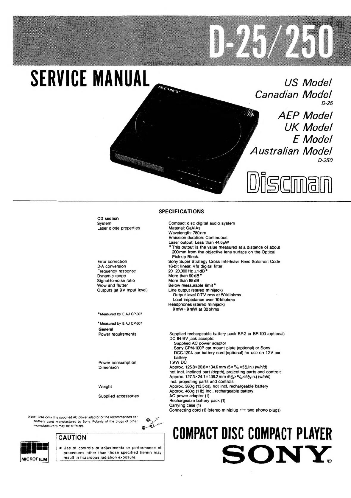
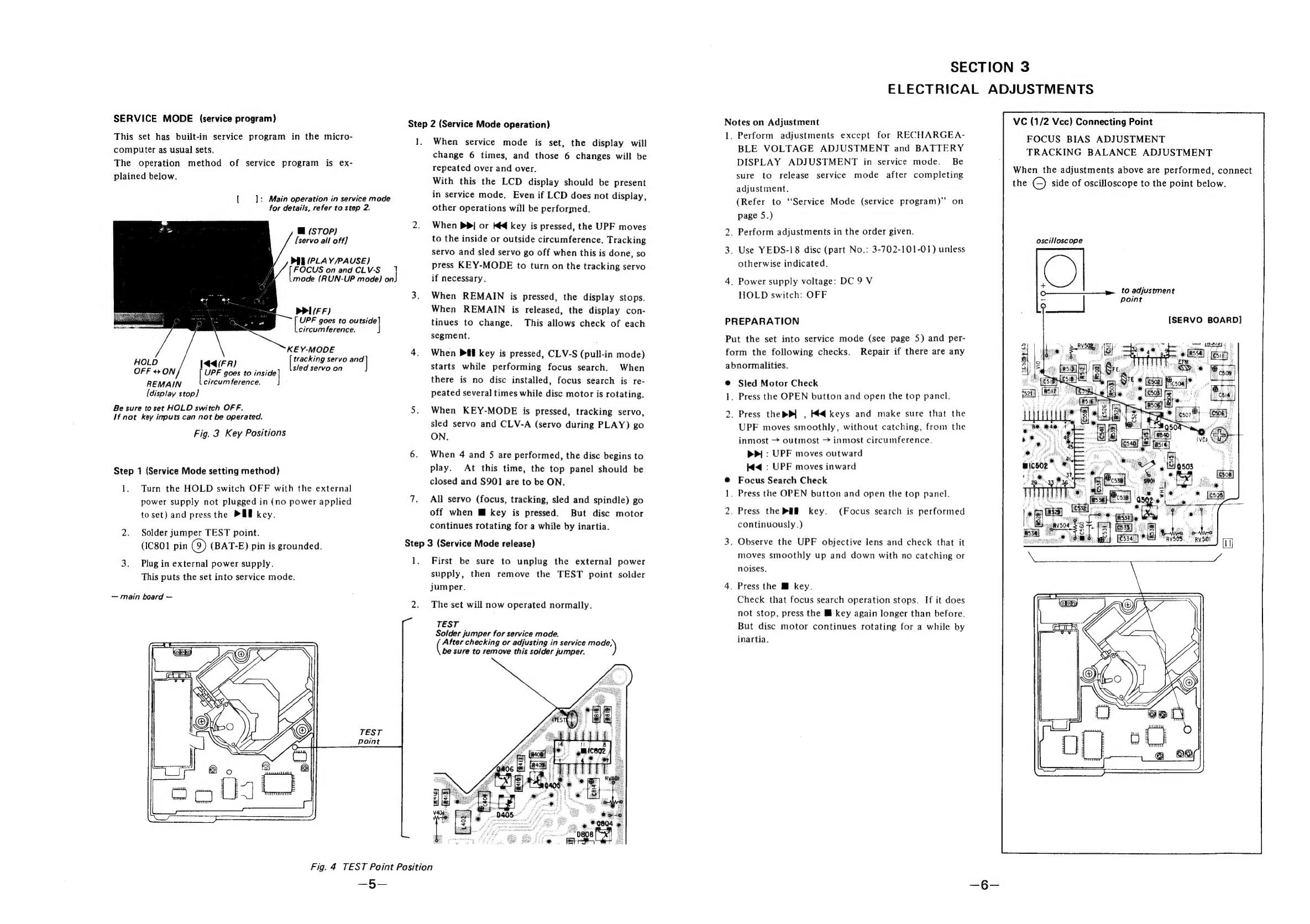
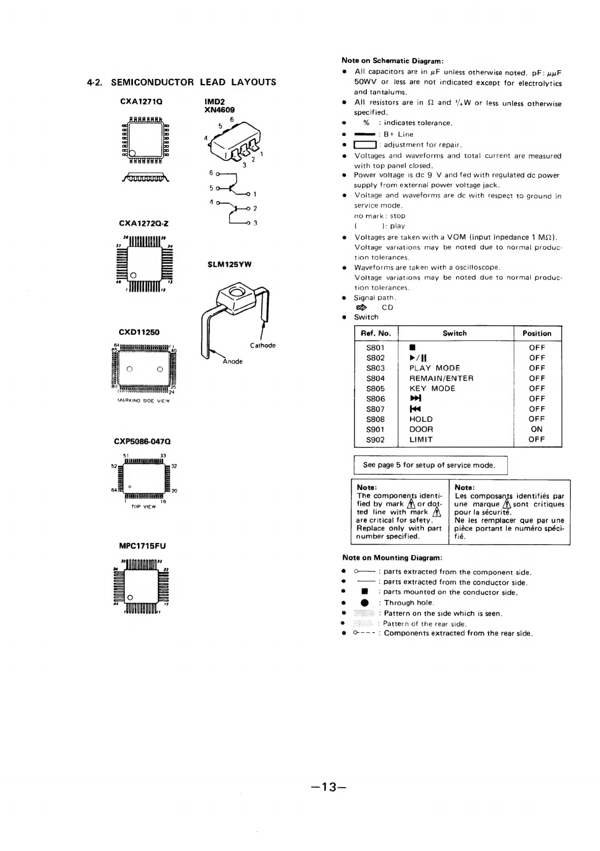
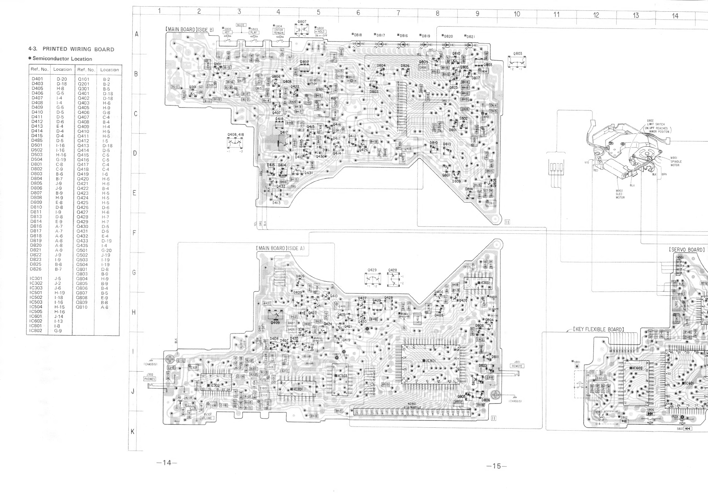
Sony Disman D-25 User manual
Other Sony CD Player manuals

Sony
Sony CDP-CX151 User manual

Sony
Sony Walkman D-NE004 User manual

Sony
Sony D-FJ61 D-FJ65 User manual

Sony
Sony CD Walkman D-FJ405 User manual

Sony
Sony D-NE710 ATRAC Guide User manual

Sony
Sony MZ-N707 OpenMG Jukebox NOTES on installing &... User manual

Sony
Sony CFD-G30 - Cd Radio Cassette-corder User manual

Sony
Sony CFD-V7 User manual

Sony
Sony MZ-NE410 - Net MD Walkman MiniDisc Recorder User manual

Sony
Sony CD Walkman D-EQ550 User manual

Sony
Sony CDP-XE800 User manual

Sony
Sony SCD-XA1200ES User manual

Sony
Sony CDX-GT828U User manual

Sony
Sony CDP-M201 User manual

Sony
Sony CDP-CX55 - 50 Disc Cd Changer User manual

Sony
Sony Walkman D-F415 User manual

Sony
Sony CDP-C591 User manual

Sony
Sony CDX-GT25MPW - Fm/am Compact Disc Player User manual

Sony
Sony D-FJ210 - CD Walkman Player User manual

Sony
Sony MCE-K850 User manual