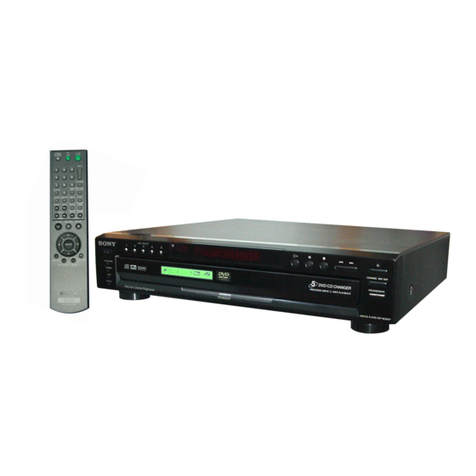
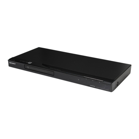
Sony HCD-LF1 User manual

SERVICE MANUAL
Sony Corporation
Home Audio Division
Published by SonyTechno Create Corporation
US Model
Canadian Model
AEP Model
UK Model
E Model
Australian Model
SUPER AUDIO CD/DVD PLAYER
9-879-139-03
2005I16-1
© 2006.09
Ver 1.2 2006.09
SPECIFICATIONS
HCD-LF1
•HCD-LF1 is DVD/CD DECK system in DAV-LF1.
Model Name Using Similar Mechanism NEW
Mechanism Type CDM80AT-DVBU29T
Optical Pick-up Name DBU-3
*Manufactured under license from Dolby Laboratories.
“Dolby”, “Pro Logic”, and the double-D symbol are trademarks
of Dolby Laboratories.
**Manufactured under license from Digital Theater Systems, Inc.
“DTS”, “DTS-ES”, and “DTS Digital Surround” are trademarks
of Digital Theater Systems, Inc.
Super Audio CD/DVD system
Laser Semiconductor laser
(Super Audio CD/DVD: λ
= 650 nm)
(CD: λ= 780 nm)
Emission duration:
continuous
Signal format system
North America,
Latin America: NTSC
Other regions: NTSC, PAL
Frequency response (at 2 CH STEREO mode)
DVD (PCM): 2 Hz to 22
kHz (±1.0 dB)
CD: 2 Hz to 20 kHz (±1.0
dB)
Harmonic distortion Less than 0.03 %
Dimensions (approx.) 568 ×200 ×120 mm
(22
3
/
8
×7
7
/
8
×4
3
/
4
inches) (w/h/d) incl.
projecting parts
Mass (approx.) 4.7 kg (10 lb 6 oz)
Design and specifications are subject to change
without notice.

2
HCD-LF1
Notes on chip component replacement
•Never reuse a disconnected chip component.
•Notice that the minus side of a tantalum capacitor may be
damaged by heat.
Flexible Circuit Board Repairing
•Keep the temperature of the soldering iron around 270 °C
during repairing.
•Do not touch the soldering iron on the same conductor of the
circuit board (within 3 times).
•Be careful not to apply force on the conductor when soldering
or unsoldering.
UNLEADED SOLDER
Boards requiring use of unleaded solder are printed with the lead-
free mark (LF) indicating the solder contains no lead.
(Caution: Some printed circuit boards may not come printed with
the lead free mark due to their particular size)
: LEAD FREE MARK
Unleaded solder has the following characteristics.
•Unleaded solder melts at a temperature about 40 °C higher
than ordinary solder.
Ordinary soldering irons can be used but the iron tip has to be
applied to the solder joint for a slightly longer time.
Soldering irons using a temperature regulator should be set to
about 350 °C.
Caution: The printed pattern (copper foil) may peel away if
the heated tip is applied for too long, so be careful!
•Strong viscosity
Unleaded solder is more viscou-s (sticky, less prone to flow)
than ordinary solder so use caution not to let solder bridges
occur such as on IC pins, etc.
•Usable with ordinary solder
It is best to use only unleaded solder but unleaded solder may
also be added to ordinary solder.
SAFETY-RELATED COMPONENT WARNING!!
COMPONENTS IDENTIFIED BY MARK 0OR DOTTED LINE
WITH MARK 0ON THE SCHEMATIC DIAGRAMS AND IN
THE PARTS LIST ARE CRITICAL TO SAFE OPERATION.
REPLACE THESE COMPONENTS WITH SONY PARTS WHOSE
PART NUMBERS APPEAR AS SHOWN IN THIS MANUAL OR
IN SUPPLEMENTS PUBLISHED BY SONY.
ATTENTION AU COMPOSANT AYANT RAPPORT
À LA SÉCURITÉ!
LES COMPOSANTS IDENTIFIÉS PAR UNE MARQUE 0SUR
LES DIAGRAMMES SCHÉMATIQUES ET LA LISTE DES
PIÈCES SONT CRITIQUES POUR LA SÉCURITÉ DE
FONCTIONNEMENT. NE REMPLACER CES COM- POSANTS
QUE PAR DES PIÈCES SONY DONT LES NUMÉROS SONT
DONNÉS DANS CE MANUEL OU DANS LES SUPPLÉMENTS
PUBLIÉS PAR SONY.
CAUTION
Use of controls or adjustments or performance of procedures
otherthanthose specifiedhereinmayresult in hazardousradiation
exposure.
Laser component in this product is capable of emitting radiation
exceeding the limit for Class 1.
This appliance is classified as a
CLASS 1 LASER product.
The CLASS 1 LASER
PRODUCT MARKING is
located on the rear exterior.
DVD player :
HCD-LF1
DVD player : HCD-LF1
Sub woofer :
SA-WSLF1
Sub woofer : SA-WSLF1
Front speaker :
SS-TSLF1(R)
SS-TSLF1L(L)
Front speaker : SS-TSLF1(R)
SS-TSLF1L(L)
Center speaker :
SS-CTLF1
Center speaker :
SS-CTLF1
Surround speaker :
SS-TSLF1W(R)
SA-TSLF1(L)
Surround speaker : SS-TSLF1W(R)
SA-TSLF1(L)
Remote
commander :
RM-SP320
Remote commander :
RM-SP320
Units required for
operation
check
Unit.
need to
checking
aa a
aa a
aaa
a
a
a
aaa a
a
*1
*1
*2
*1 Only the defective unit. *2 Either one of them.
Units with amark: The units that are required for the system operation check during repair service
However, there can be a case that some units of the system need to not be brought into repair shop depending on the unit. that became defective.
• The units that are required for the system operation check during repair service

3
HCD-LF1
TABLE OF CONTENTS
1. SERVICING NOTES ................................................ 4
2. GENERAL ................................................................... 8
3. DISASSEMBLY
3-1. Disassembly Flow ........................................................... 10
3-2. Stand Section ................................................................... 11
3-3. Cover (MAIN/CDM)....................................................... 11
3-4. Chassis Section................................................................ 12
3-5. DLED Board.................................................................... 12
3-6. STBY KEY Board, EJECT KEY Board ......................... 13
3-7. Mechanism Deck (CDM80AT-DVBU29T)..................... 13
3-8. DMB07 Board ................................................................. 14
3-9. DISPLAY Board.............................................................. 14
3-10. I/O Board ......................................................................... 15
3-11. DVD-POW Board............................................................ 15
3-12. Chassis (Top) ................................................................... 16
3-13. Lever (Loading R/L)........................................................ 17
3-14. Disc Stop Lever, Disc Sensor Lever ................................ 18
3-15. DRIVER Board ............................................................... 18
3-16. RF Board ......................................................................... 19
3-17. Optical Pick-up (DBU-3) ................................................ 19
3-18. Base Unit ......................................................................... 20
3-19. Lever (BU Lock) ............................................................. 20
3-20. Close Lever...................................................................... 21
3-21. DIR Lever, Gear (IDL-B) ................................................ 21
3-22. Gear (IDL-C) ................................................................... 22
4. TEST MODE ............................................................... 23
5. ELECTRICAL ADJUSTMENTS .......................... 32
6. DIAGRAMS
6-1. Block Diagram — RF SERVO Section — ................... 34
— DVD DSP Section — ................................................. 35
— AUDIO Section —...................................................... 36
— MAIN Section — ....................................................... 37
6-2. Printed Wiring Board — RF Section — ......................... 38
6-3. Schematic Diagram — RF Section — ........................... 39
6-4. Printed Wiring Board — DRIVER Section — ............... 40
6-5. Schematic Diagram — DRIVER Section — ................. 40
6-6. Printed Wiring Board — DMB07 Section (Side A) — .. 41
6-7. Printed Wiring Board — DMB07 Section (Side B) — .. 42
6-8. Schematic Diagram — DMB07 Section (1/10) — ........ 43
6-9. Schematic Diagram — DMB07 Section (2/10) — ........ 44
6-10. Schematic Diagram — DMB07 Section (3/10) — ........ 45
6-11. Schematic Diagram — DMB07 Section (4/10) — ........ 46
6-12. Schematic Diagram — DMB07 Section (5/10) — ........ 47
6-13. Schematic Diagram — DMB07 Section (6/10) — ........ 48
6-14. Schematic Diagram — DMB07 Section (7/10) — ........ 49
6-15. Schematic Diagram — DMB07 Section (8/10) — ........ 50
6-16. Schematic Diagram — DMB07 Section (9/10) — ........ 51
6-17. Schematic Diagram — DMB07 Section (10/10) — ...... 52
6-18. Printed Wiring Board — DVD-POW Section — ........... 53
6-19. Schematic Diagram — DVD-POW Section (1/2) — ..... 54
6-20. Schematic Diagram — DVD-POW Section (2/2) — ..... 55
6-21. Printed Wiring Board — DISPLAY Section — ............. 56
6-22. Schematic Diagram — DISPLAY Section — ................ 57
6-23. Printed Wiring Board — TOUCH KEY Section —....... 58
6-24. Schematic Diagram — TOUCH KEY Section — ......... 59
6-25. Printed Wiring Board — I/O Section — ........................ 60
6-26. Schematic Diagram — I/O Section — ........................... 61
7. EXPLODEDVIEWS
7-1. Stand Section ................................................................... 84
7-2. Main Section.................................................................... 85
7-3. Chassis Section................................................................ 86
7-4. Mechanism Deck Section-1 (CDM80AT-DVBU29T) .... 87
7-5. Mechanism Deck Section-2 (CDM80AT-DVBU29T) .... 88
7-6. Mechanism Deck Section-3 (CDM80AT-DVBU29T) .... 89
7-7. Base Unit Section ............................................................ 90
8. ELECTRICAL PARTS LIST .................................. 91

4
HCD-LF1 SECTION 1
SERVICING NOTES
NOTES ON HANDLINGTHE OPTICAL PICK-UP BLOCK
OR BASE UNIT
The laser diode in the optical pick-up block may suffer electrostatic
break-down because of the potential difference generated by the
charged electrostatic load, etc. on clothing and the human body.
During repair, pay attention to electrostatic break-down and also
use the procedure in the printed matter which is included in the
repair parts.
The flexible board is easily damaged and should be handled with
care.
NOTES ON LASER DIODE EMISSION CHECK
The laser beam on this model is concentrated so as to be focused on
the disc reflective surface by the objective lens in the optical pick-
up block. Therefore, when checking the laser diode emission,
observe from more than 30 cm away from the objective lens.
LASER DIODE AND FOCUS SEARCH OPERATION
CHECK
Carryout the“S curve check” in “CD sectionadjustment” and check
that the S curve waveform is output several times.
NOTE 1: Regarding the notification symbol “R”
Because the number of the operating buttons of this product
are limited, some operations require use of the operating
buttons of the remote commander (RM-SP320 supplied with
the product). When a specific operation requires use of the
operatingbuttons ofthe remote commander (RM-SP320),“R”
is added to the specific operating procedure in this manual.
Example MENU/NO “R” The MENU/NO button of remote
commander.
NOTE 2: Incorrect operations may be performed if the test mode is not
entered properly.
In this case, press the ?/1 button to turn the power off, and
retry to enter the test mode.
DISCTRAY LOCK
The disc tray lock function for the antitheft of an demonstration
disc in the store is equipped.
Procedure :
1. Press the ?/1 button to turn the set on.
2. Press the FUNCTION “R” button or touch the FUNCTION
button to set DVD function.
3. Insert a disc.
4. While the power is ON (excluding the mode of Power-ON
Animation mode), touch the x Sensor (on Touch Panel) and
press the A button simultaneously for several seconds.
5. The “Locked” display appears for a while and disc cannot be
removed any more even if the A button is pressed.
*To release this mode, repeat the above operation. The
“Unlocked” display appears and the Disc Tray Lock mode is
canceled.
Note: When “LOCKED” is displayed, the slot lock is not released by
turning power on/off with the ?/1 button.
NOTE OF REPLACING THE DMB07 BOARD
When replacing the DMB07 board, since the adjustment value is
not set up correctly, “DriveAuto Adjustment” can’t be performed.
In this case, initialize Memory in the following procedures.
Procedure:
1. Set the test mode. (See page 25)
2. Pressthe[2] keyoftheremote commander,and setthe“DRIVE
MANUAL OPERATION”. (See page 27)
3. Press the [6] key of the remote commander, and set the “2-6,
Memory Check”. (See page 29)
4. Pressthe [CLEAR] keyof theremote commander,and initialize
Memory.

5
HCD-LF1
•CAUTION-1 (REPLACING THE TOUCH KEY BOARD)
CL402
TOUCH KEY BOARD
TOUCH PAD (B) BOARD
TOUCH PAD (A) BOARD
CL403 CL413
CL404
CL414
CL405
CL415
CL416
CL400
CL411
CL401
CL410
CL406
CL412
*
When the TOUCH KEY BOARD is replaced, wire theTOUCH KEY BOARD securely to
the TOUCH PAD (A) BOARD and TOUCH PAD (B) BOARD as shown in the figure.
•NOTE
*
The performance of the main unit can be connected with the remote controller, even if the panel is not connected.

6
HCD-LF1
•SERVICING POSITION-1 (MECHANISM DECK)
extension cable
J-2501-103-A (29P/L300) MECHANISM DECK
*
Connect the DVD-POW BOARD and the MECHANISM DECK with the extension cable, and inspect
the MECHANISM DECK.
•CAUTION-2 (REPLACING THE CONNECTING CORD)
*
When replacing the connecting cord, fix it at the position in the figure so that the copper conductor of
the cord and the steel plate contact (GND) adequately.
copper conductor of the cord
connecting cord

7
HCD-LF1
•SERVICING POSITION-2 (DMB07 BOARD)
extension cable
J-2501-199-A (25P/L300) extension cable
J-2501-225-A (9P/L300)
extension cable
J-2501-243-A (17P/L300)
DMB07 BOARD
I/O BOARD
*
Connect the I/O BOARD and the DMB07 BOARD by using the three extension cables, and inspect the DMB07 BOARD.

8
HCD-LF1 SECTION 2
GENERAL This section is extracted
from instruction manual.
Front Panel
Top Panel
ADISC indicator*
BTouch Panel Sensor (41)
CFront panel display (104)
DDOLBY DIGITAL indicator*
EDTS indicator*
FDOLBY PRO LOGIC II indicator*
GD.C.S. indicator*
*Lights up when activated.
H[/1(power) switch/standby indicator
(39)
IDisc slot (39)
JZ(eject) (39)
VOL.
+
-
FUNCTION

9
HCD-LF1
Remote
Note
This remote control glows in the dark. However,
before glowing, the remote must be exposed to light for
awhile.
A
Z
(eject) (39, 40)
BDISPLAY (55, 58, 80)
CSLEEP (83)
D./>, PRESET –/+ (40, 43, 80, 81)
EH(play) (40, 42, 47, 48, 51, 52)
FDVD TOP MENU/ALBUM– (43, 45, 46)
GC/X/x/c/ENTER (34, 43, 43, 45, 46, 48,
48, 50, 51, 53, 60, 67, 68, 69, 71, 79, 81,
83, 85, 91)
HDVD DISPLAY (45, 46, 50, 51, 53, 58, 59,
60, 67, 68, 69)
IAUTO FORMAT DIRECT (62, 63)
JDSGX (66)
KDVD SETUP (34, 71, 85)
LSUBTITLE (68)
MAUDIO (60)
NANGLE (67)
ONumber buttons (43, 43, 48, 53, 67, 69,
71, 74, 76)
PENTER
QTUNER MENU (79, 81)
RTV [/1(on/standby) (74)
S"/1(standby) (34, 39, 80)
TSONY TV DIRECT (76)
UTUNER/BAND (79, 80, 81)
VFUNCTION (39, 78, 80, 81)
Wm/M/SLOW / , TUNING –/+ (47,
52, 79, 80)
Xx(stop) (40, 42, 43, 69, 80)
YX(pause) (40)
ZMUTING (40)
wj DVD MENU/ALBUM+ (43, 45, 46)
wk VOL +/– (40, 80)
wl ORETURN (43, 45, 46, 48, 53, 69, 71,
85)
e; MODE (63, 64)
ea NIGHT MODE (66)
es PLAY MODE (48, 50)
ed REPEAT (48, 51)
ef TV (74, 76)
eg TV/VIDEO (74, 76)
eh TV CH +/– (74, 76)
ej TV VOL +/– (74)
ek AMP MENU (29, 78, 83, 91)
el CLEAR (34, 48, 53)
r; FM MODE (80)
Open the cover.

10
HCD-LF1 SECTION 3
DISASSEMBLY
3-1. DISASSEMBLY FLOW
•This set can be disassembled in the order shown below.
•The dotted square with arrow ( ) prompts you to move to the next job when all of the works within the dotted square ( ) are
completed.
SET
3-2.
STAND SECTION
(Page 11)
3-4.
CHASSIS SECTION
(Page 12)
3-3.
COVER (MAIN/CDM)
(Page 11)
3-7.
MECHANISM DECK
(
CDM80AT-DVBU29T)
(Page 13)
3-12
. CHASSIS (TOP)
(Page 16) 3-15
. DRIVER BOARD
(Page 18)
3-8
. DMB07 BOARD
(Page 14) 3-9
. DISPLAY BOARD
(Page 14) 3-5
. DLED BOARD
(Page 12)
3-10
. I/O BOARD
(Page 15) 3-11
. DVD-POW BOARD
(Page 15)
3-16
. RF BOARD
(Page 19) 3-18
. BASE UNIT
(Page 20)
3-13
. LEVER (LOADING R / L)
(Page 17) 3-14
. DISC STOP LEVER,
DISC SENSOR LEVER
(Page 18)
3-17
. OPTICAL PICK-UP
(DBU-3)
(Page 19)
3-19
. LEVER (BU LOCK)
(Page 20)
3-
6.STBY KEY BOARD,
EJECT KEY BOARD
(Page 13)
3-20
. CLOSE LEVER
(Page 21)
3-22
. GEAR (IDL-C)
(Page 22)
3-21
. DIR LEVER,
GEAR (IDL-B)
(Page 21)

11
HCD-LF1
3-2. STAND SECTION
3
cover (rear)
4
stand section
2
four claws
1
two screws
(HEX 4
×
10)
3-3. COVER (MAIN/CDM)
q;
four screws
(+BVTP 3
×
8)
qa
cover (CDM)
1
two covers (SH)
9
four covers (SH)
8
cover (MAIN)
2
two screws
(+BVTP 3
×
8)
3
two screws
6
four claws
4
six claws
5
hook
7
cover (SYS)

12
HCD-LF1
3-4. CHASSIS SECTION
3-5. DLED BOARD
4
four screws
(+BVTP 2.6
×
8)
1
screw
(+BVTP 3
×
8)
5
six screws
(+BVTP 3
×
8)
8
chassis section
3
side panel (CDM)
6
four dowels
7
wire (flat type)
(18core) (CN401
)
2
screw
+BV3 (3-CR)
1
hook
3
two dowels
2
indicator (DISC)
5
DLED board
4
connector (3p)

13
HCD-LF1
3-6. STBY KEY BOARD, EJECT KEY BOARD
3-7. MECHANISM DECK (CDM80AT-DVBU29T)
qa
escutcheon assy
1
two screws
(+BVTP 2.6
×
8)
4
two screws
(+BVTP 2.6
×
8
)
8
two screws
(+BVTP 2.6
×
8)
7
bracket (escutcheon)
3
connector (2p)
2
connector (4p)
9
STBY KEY board
q;
EJECT KEY board
5
two dowels
6
two hooks
1
four screws
(+BVTP 3
×
8)
2
wire (flat type)
(29core)
3
connector
(7p) (CN701)
4
mechanism deck
(CDM80AT-DVBU29T
)

14
HCD-LF1
3-8. DMB07 BOARD
3-9. DISPLAY BOARD
1
five screws
(+BVTP 3
×
8)
7
DMB07 board
3
wire (flat type)
(13core) (CN101)
2
wire (flat type)
(17core) (CN105)
4
wire (flat type)
(25core) (CN107)
5
wire (flat type)
(29core) (CN501)
6
connector
(13p) (CN102)
9
connector
(2p) (CN402)
8
connector
(2p) (CN401)
q;
heat sink (DMB)
5
wire (flat type)
(12 core) (CN451)
6
DISPLAY board
1
three screws
(+BVTP 3
×
8)
3
screw
(+BVTP 3
×
8)
2
indicator (FUNC)
4
clamp (L35)

15
HCD-LF1
3-10. I/O BOARD
3-11. DVD-POW BOARD
6
wire (flat type)
(25core) (CN101)
7
wire (flat type)
(9core) (CN204)
8
wire (flat type)
(17core) (CN201)
2
connector
(12p) (CN203)
3
connector
(8p) (CN202)
4
connector
(2p) (CN103)
9
I/O board
5
connector
(7p) (CN102)
1
four screws
(+BVTP 3
×
8)
7
wire (flat type)
(12 core) (CN303)
9
wire (flat type)
(18 core) (CN304)
2
connector
(9p) (CN301)
8
connector
(8p) (CN901)
4
connector
(4p) (CN902)
5
connector
(7p) (CN305)
6
connector
(14p) (CN302)
1
four screws
(+BVTP 3
×
8)
q;
DVD-POW board
3
connector
(2p) (CN910)

16
HCD-LF1
3-12. CHASSIS (TOP)
1
screw
(+BVTP 2.6
×
8)
4
three screws
(+BVTP 2.6
×
8)
3
two screws
(+P 2
×
10)
5
chassis (top)
2
lever (CL UP2
)

17
HCD-LF1
3-13. LEVER (LOADING R/L)
lever (loading R)
Align the horizontal position.
lever (loading L)
Install the
both levers so that they move symmetrically.
2
two hooks
4
two hooks
3
lever (loading L)
5
lever (loading R)
spr-T (loading L) spr-T (loading R)
1
1
PRECAUTION DURING LEVER (LOADING R / L) INSTALLATION

18
HCD-LF1
3-14. DISC STOP LEVER, DISC SENSOR LEVER
3-15. DRIVER BOARD
chassis (top)
hole
Install the disc stop lever so that the both holes
are aligned.
hole
1
gear (cap)
3
two claws
5
two hooks
6
disc stop lever disc stop lever
4
disc sensor lever
PRECAUTION DURING DISC STOP LEVER INSTALLATION
2
gear (IDL L)
3
Remove soldering
from the two points.
2
three screws
(+BVTP 2.6
×
8
)
5
DRIVER board
4
motor (pully) assy
1
belt (MOT)

19
HCD-LF1
3-16. RF BOARD
3-17. OPTICAL PICK-UP (DBU-3)
4
RF board
2
wire (flat type)
(CN003)
3
wire (flat type)
(CN001)
1
claw
1
two step screws (M)
2
step screw (M)
3
two insulators (RB)
4
insulator
6
optical pick-up
(DBU-3)
5
tension coil spring (H-1)

20
HCD-LF1
3-18. BASE UNIT
3-19. LEVER (BU LOCK)
4
floating screw
(+PTPWHM 2.6)
5
floating screw
(+PTPWHM 2.6)
3
holder down spring
6
base unit
1
screw
(+BVTP 2.6
×
8)
2
lever (CL UP2)
5
three hooks
4
6
lever (BU lock)
1
gear (cap)
2
gear (BU lock)
3
floating screw
(+PTPWHM 2.6)
Table of contents
Other Sony DVD Player manuals

Sony
Sony DVP-NS57P - Cd/dvd Player User manual

Sony
Sony DVP-NC650V User manual

Sony
Sony DVP-NS710H User manual

Sony
Sony DVP-SR700H User guide

Sony
Sony DVP-SR450K User guide

Sony
Sony DVP-SR110 User manual

Sony
Sony DVP-NS508P User manual

Sony
Sony DVP-NS305 User manual

Sony
Sony DVP-SR101P User manual

Sony
Sony DVP-FX97 User manual

Sony
Sony DVP-F21 - Cd/dvd Player User manual

Sony
Sony DVP-NS900V - Sacd/dvd Player User manual

Sony
Sony DVP-S533D - Cd/dvd Player User manual

Sony
Sony DVP-M35 User manual

Sony
Sony DVP-S7000 Instruction Manual

Sony
Sony DVP-C660 - 5 Disc DVD Player User manual

Sony
Sony RMT-D139P User manual

Sony
Sony DVP-NS700H User manual

Sony
Sony HCD-DZ275M User manual

Sony
Sony DVP-NS78H User manual