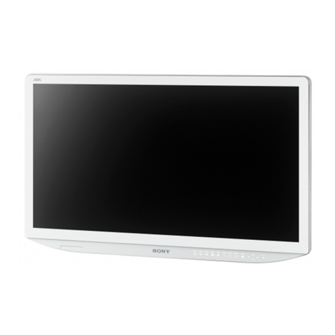
Sony LMD-3251MT User manual

LCD Monitor
Interface Manual for Programmers
LMD-3251MT
4-464-723-11(1)
© 2013 Sony Corporation

Table of Contents
2
Table of Contents
RS-232C
Communication Format ........................................ 3
Command Block Format ...................................... 4
Communication Protocol ...................................... 4
Connections ............................................................ 5
Features of the Command Protocol ..................... 5
Command Table .................................................... 6
Command Description .......................................... 7
Input Config (21H) ............................................. 7
Control Data (23H) ............................................ 7
Display Data (24H) ............................................ 8
User Memory (25H) ........................................... 8
Memory Name (26H) ......................................... 9
I/P Mode (27H) ................................................ 10
Selected Offset (28H) ....................................... 10
On Switch Function (29H) ............................... 10
Off Switch Function (2AH) ............................. 10
Select Display (2BH) ....................................... 11
Select Menu (2CH) .......................................... 11
Scan Aspect (2DH) .......................................... 11
Select Config Data (2FH) ................................. 11
Picture Config (30H) ........................................ 12
Multi Display (31H) ......................................... 12
BKM-256DD (3DH) ........................................ 13
3D Function 1 (3EH) ........................................ 13
3D Function 2 (3FH) ........................................ 14
White Balance Data (40H) ............................... 14
White Balance Data Copy (42H) ..................... 15
User Memory Data (43H) ................................ 16
3D Offset (49H) ............................................... 17
Select 3D Offset (4AH) .................................... 18
Status Sense (60H) ........................................... 18
White Balance Sense (61H) ............................. 18
3D Offset Sense (63H) ..................................... 18
User Memory Sense (65H) .............................. 18
Status Remote (6EH) ....................................... 19
Status Reply (70H) ........................................... 19
White Balance Reply (71H) ............................. 19
3D Offset Reply (73H) ..................................... 19
User Memory Reply (75H) .............................. 19
Status Remote Reply (7EH) ............................. 20
ACK Reply (04H) ............................................ 21
NAK Reply (05H) ............................................ 21
Ethernet
Overview .............................................................. 22
Connections .......................................................... 22
Communication Protocol .................................... 23
SDAP ................................................................ 23
SDCP ................................................................ 23
Command Block Format .....................................24
SDAP Packets ...................................................24
SDCP Packets ...................................................25
VMC Command Description ..............................27
Format of VMC Packets ...................................27
Details of VMC Commands .............................28

Communication Format 3
RS-232C
RS-232C
Communication Format
Asynchronous, bit serial signal
• Based on RS-232C
• Data signaling rate: 38400 bit/sec
• Start bit: 1 bit
• Data bit: 8 bits
• Parity: Even
• Stop bit: 1 bit
START
BIT
BIT
0(LSB)
BIT
1
BIT
2
BIT
3
BIT
4
BIT
5
BIT
6
BIT
7(MSB)
PA R I T Y
BIT
STOP
BIT
1(Mark)
0(Space)

Command Block Format / Communication Protocol
4
RS-232C
Command Block Format
Data communication between the remote controller and
the monitor is performed in accordance with the
following format.
• STX: start of text code value equals 02H.
• Byte Count
This indicates the number of data bytes (maximum
255 bytes) which have been inserted between this byte
and the Checksum byte. Values 00H, 01H, 02H are
illegal values.
• Destination address:
One byte address value which defines who receives
the message. The value 01H should be specified.
• Source address:
One byte address value which defines who transmits
the message. The destination to which the reply
should be sent is shown with this value. A value from
41H to 7FH should be specified.
• Command Block
This designates a particular command. Refer to
“Command Description” (on page 7) for the details.
• Checksum
This value is set so that the bottom eight bits of the
sum of all bytes from the byte count to the checksum
inclusive are zero.
Communication
Protocol
The remote controller should take the initiative in
communication between the remote controller and the
monitors.
The monitor will carry out one of the following actions
when receiving the message.
• When the received message is an undefined message,
a communication error occurs or the automatic
adjustment of APA or AUTO CHROMA/PHASE is
working, a NAK (05H) is issued.
• When the received command is a question, the specific
replay and data are issued.
• When the received command is anything else, an ACK
is issued.
The next message can be received as soon as a NAK is
issued from the monitor to the remote controller.
Notes
• If there are not enough or too many data bytes of data
values then a NAK is issued and no values are
specified.
• Bits which are not specified here are undefined bits
and their values are always ignored.
STX Byte
Count
Destination
Address
Source
Address
Command
Block
Checksum
1 byte 1 byte 1 byte 1 byte n bytes 1 byte

Connections / Features of the Command Protocol 5
RS-232C
Connections
Pin assignment for the RS-232C connector is as follows.
Features of the
Command Protocol
This protocol provides the following features when
individual monitors are controlled.
• Switch functions can be changed.
• The ability to remotely make settings and adjustments
normally made with the monitor’s menu.
Pin number Signal
1NC
2RX
3TX
4NC
5GND
6NC
7RTS
8CTS
9NC
15
69

Command Table
6
RS-232C
Command Table
Using this protocol, the following commands can be
executed by the monitors.
All values in the following table are hexadecimal.
× : varies depending on the number of data items.
Command from Remote Controller Return from Monitor
Specific
Command Name Data Bytes Specific Command Name Data Bytes
21 Input Config 2 04 ACK 0
23 Control Data × 04 ACK 0
24 Display Data × 04 ACK 0
25 User Memory 1 04 ACK 0
26 Memory Name × 04 ACK 0
27 I/P Mode 1 04 ACK 0
28 Selected Offset 1 04 ACK 0
29 On Switch Function 1 04 ACK 0
2A Off Switch Function 1 04 ACK 0
2B Select Display 1 04 ACK 0
2C Select Menu 1 04 ACK 0
2D Scan Aspect 1 04 ACK 0
2F Select Config Data 2 04 ACK 0
30 Picture Config 1 04 ACK 0
31 Multi Display 3 04 ACK 0
3D BKM-256DD 2 04 ACK 0
3E 3D Function 1 2 04 ACK 0
3F 3D Function 2 2 04 ACK 0
40 White Balance Data × 04 ACK 0
42 White Balance Data Copy 1 04 ACK 0
43 User Memory Data × 04 ACK 0
49 3D Offset 2 04 ACK 0
4A Select 3D Offset 1 04 ACK 0
60 Status Sense 1 70 Status Reply ×
61 White Balance Sense 1 71 White Balance Reply 7
63 3D Offset Sense 1 73 3D Offset Reply 7
65 User Memory Sense 1 75 User Memory Reply ×
6E Status Remote 0 7E Status Remote Reply 1

Command Description 7
RS-232C
Command Description
Input Config (21H)
Used to control the current video signal being displayed
on the monitor.
The switches effectively being controlled are Input
Connector and Preset White Balance.
The command has two sections.
1. Information being changed
2. Values to be applied
1. Information being changed
The values are specified as follows:
1Input connector information
2Preset white balance information
When 1 is set in the bit position, information for the bit
is applied. When 0 is set, information for the bit is
ignored. When 1 is set in the 1and 2bit positions,
information on both items is applied.
2. Values to be applied
The values are specified as follows:
1Input connector
COMPOSITE = 0000
Y/C = 0010
RGB = 0100
COMPONENT = 0101
DVI = 1000
HD15 = 1001
OPTION A-1 = 0110
OPTION A-2 = 0111
OPTION B-1 = 1010
OPTION B-2 = 1011
The values which are specified here are applied to the
current monitor state if the input setting is set to ON.
If the input setting is set to OFF, the values are
ignored.
2Preset white balance information
D56 = 0001
D65 = 0011
D93 = 0000
USER CONFIG 1 = 0010
USER CONFIG 2 = 0100
USER CONFIG 3 = 0110
USER CONFIG 4 = 0111
USER CONFIG 5 = 1000
The values specified here are applied to the current
monitor state.
Control Data (23H)
Defines the keys on the front panel and data in the USER
CONTROL menu.
The command has two sections.
1. The element of CONTROL data being sent
2. CONTROL data value
1. The element of CONTROL data being sent
The element of CONTROL data being sent is the first
byte of data contained within the command block of the
message.
Several items of CONTROL data can be specified in one
message stream. When the bit of an item is set to 1, the
data value is changed, and it is set to 0, the data value is
not changed. When the byte value is 0, no data are
changed and an ACK is issued.
The values are specified as follows:
1CONTRAST
2APERTURE
3BRIGHTNESS
4PHASE
5CHROMA
6BACKLIGHT
2. CONTROL data value
Each value is one byte of data. APERTURE is specified
as 0 to 6, BACKLIGHT is specified as 0 to 5 and others
are 0 to 100 (8 bit data, MSB is a mark data. If the value
is a negative number, it is represented as a complement
of 2). The data is defined from the lower bit item to the
higher one. For example, if the PHASE and
CONTRAST data are defined, the PHASE data is
specified in the first byte and the CONTRAST data is
specified in the next byte.
76543210
12

Command Description
8
RS-232C
The values are specified as follows:
1Mark data
+ = 0
– = 1
2Numerical value data
The values of the CONTROL data which is defined by
this command are applied to the current monitor state.
Display Data (24H)
Defines PITCH, DOT PHASE, SIZE H, SIZE V, SHIFT
H and SHIFT V data in the USER CONFIG menu.
The command has two sections.
1. The element of USER CONFIG data being sent
2. USER CONFIG data value
1. The element of USER CONFIG data being
sent
The element of USER CONFIG data being sent is the
first byte of the command block of the message.
Several items of USER CONFIG data can be specified
in one message stream. If 1 is indicated in the bit
position, the data is changed and 0 is indicated, no data
is changed.
If the byte value is 0, no data are changed and an ACK
is issued. If the RESET value is set to 1, all items are
specified to the default setting.
The values are specified as follows:
1RESET
2PITCH
3DOT PHASE
4SIZE H
5SIZE V
6SHIFT H
7SHIFT V
2. USER CONFIG data value
Each adjustment value is one byte of data (8 bit data,
MSB is a mark data. If the value is a negative number, it
is represented as a complement of 2). The data are
defined from the subordinate bit element to the
superordinate bit element in the data bytes. For
example, if the data to be adjusted are SIZE H and
SHIFT H, then the first byte of data bytes is for SHIFT
H and the next byte is for SIZE H.
Adjustment Item Max. Min.
PITCH 0 32
DOT PHASE 0 63
SIZE H –100 +100
SIZE V –100 +100
SHIFT H * *
SHIFT V * *
* The maximum and minimum values vary according to the input signal
(resolution). See “Maximum and minimum values of SHIFT H and
SHIFT V” (page 34).
The values are specified as follows:
1Mark data
+ = 0
–= 1
2Numerical value data
This is not the data to increase or decrease the setting.
Enter the adjustment value.
The standard value (center value) of the PITCH data is
not always 0 (zero). It differs depending on the input
signals. The maximum and minimum values
mentioned above are variable values to each standard
value.
User Memory (25H)
Controls LOAD/SAVE of each data set in the USER
MEMORY menu.
The values are specified as follows:
1Control data
LOAD = 01
SAVE = 10
2User memory number
Specifies the number 01 to 20.
If a number other than the above except 00 is
specified, an ACK is issued.
When 00 is specified, the data is applied as follows:
If LOAD (01) is specified in 1, the default setting is
applied.
76543210
21
76543210
1 32 4 6 75
76543210
21
76543210
12

Command Description 9
RS-232C
If SAVE (10) is specified in 1, an ACK is issued.
Memory Name (26H)
Defines the name (ASCII) of each user memory in the
USER MEMORY menu.
The command has two sections.
1. User memory number to change the name
2. Memory name setting data
1. User memory number to change the name
Defines the user memory number to change the name.
The values are specified as follows:
1User memory number
Specifies the number 01 to 20. If a number other than 01
to 20 is specified, a NAK is issued.
2. Memory name setting data
1. Specifies the length of the name
Specifies 1 to 18 charactors.
76543210
1

Command Description
10
RS-232C
2. Specifies the name data (ASCII code)
Usable characters are as follows (42 characters):
If data other than the data listed above is specified, the message is ignored and a NAK is issued.
I/P Mode (27H)
Controls the MODE select of I/P MODE.
The values are specified as follows:
12 Mode select
01 00 INTER-FIELD
01 01 FIELD MERGE
01 10 LINE DOUBLER
The values are applied to the current monitor state.
Selected Offset (28H)
Defines the offset to be applied to COMPONENT or
NTSC signal which is selected to be displayed on the
monitor.
The values are specified as follows:
1COMPONENT signal offset
SMPTE = 01
BETA 0 = 10
BETA 7.5 = 11
2NTSC signal offset
NTSC 0 = 01
NTSC 7.5 = 10
The values are applied to the current monitor state.
On Switch Function (29H)
This command is used to set the offset value of APA,
POWER SAVING, KEY INHIBIT, Tally Lamp (green),
BLUE ONLY, MONO, MIRROR IMAGE,
BACKGROUND and SPLASH LOGO to ON.
The values are specified as follows:
12 3 4Action taken
11 001 APA applied
11 010 POWER SAVING applied
11 100 KEY INHIBIT applied
11 101 Tally Lamp (green) applied
1 11 011 BLUE ONLY applied
1 11 100 MONO applied
1 11 101 MIRROR IMAGE applied
1 11 000 BACKGROUND applied
1 00 000 10 SPLASH LOGO applied (5
seconds)
1 00 010 10 SPLASH LOGO applied (10
seconds)
Off Switch Function (2AH)
This command is used to set the offset value of APA,
POWER SAVING, KEY INHIBIT, Tally Lamp (green),
BLUE ONLY, MONO, MIRROR IMAGE,
BACKGROUND and SPLASH LOGO to OFF.
The values are specified as follows:
ASCII 0x20 0x2C 0x2D 0x2E 0x2F 0x30 0x31 0x32 0x33 0x34 0x35
Character Space , −. /012345
ASCII 0x36 0x37 0x38 0x39 0x41 0x42 0x43 0x44 0x45 0x46 0x47
Character 6 7 8 9 A B C D E F G
ASCII 0x48 0x49 0x4A 0x4B 0x4C 0x4D 0x4E 0x4F 0x50 0x51 0x52
Character H I J K L M N O P Q R
ASCII 0x53 0x54 0x55 0x56 0x57 0x58 0x59 0x5A 0x5F
Character S T U V W X Y Z _
76543210
12
76543210
21

Command Description 11
RS-232C
12 3 4Action taken
11 001 APA removed
11 010 POWER SAVING removed
11 100 KEY INHIBIT removed
11 101 Tally Lamp (green) removed
1 11 011 BLUE ONLY removed
1 11 100 MONO removed
1 11 101 MIRROR IMAGE removed
1 11 000 BACKGROUND removed
1 00 000 10 SPLASH LOGO removed (5
seconds)
1 00 010 10 SPLASH LOGO removed (10
seconds)
Select Display (2BH)
Defines the offset values of LANGUAGE and FORMAT
DISP in the menu.
The values are specified as follows:
1LANGUAGE
ENGLISH = 001
GERMAN = 010
FRENCH = 011
ITALIAN = 100
SPANISH = 101
JAPANESE = 110
CHINESE = 111
23D FORMAT DISP
AUTO = 01
ON = 10
OFF = 11
3FORMAT DISP
AUTO = 01
ON = 10
OFF = 11
Select Menu (2CH)
Defines the offset value of GAMMA, COLOR SPACE
and CHROMA in the menu.
The values are specified as follows:
1GAMMA offset
GAMMA3 (2.2) = 011
GAMMA5 (DICOM) = 101
2COLOR SPACE offset
OFF = 001
ITU-709 = 111
3CHROMA offset
OFF = 01
ON = 10
AUTO ADJUST= 11
The values are applied to the current monitor state.
If a correct signal is not input or the adjustment is in
failure, an error message is issued for AUTO ADJUST
definition.
Scan Aspect (2DH)
Defines SCAN and ASPECT in the menu.
The values are specified as follows:
1SCAN
NORMAL = 000
OVER = 001
FULL = 011
NATIVE = 101
2ASPECT
4:3 = 00
16:9 = 01
The values are applied to the current monitor state.
Select Config Data (2FH)
Defines SYNC and COMPUTER DETECT in the menu.
Define one byte each.
The values are specified as follows:
1SYNC
The sync signal is the internal one = 01
The sync signal is the external one = 10
4AUTO SYNC DETECT
The sync signal is detected manually = 01
76543210
2
1
3
76543210
3
1
2
76543210
2
1

Command Description
12
RS-232C
The sync signal is detected automatically = 10
2COMPUTER DETECT (DVI)
PRESET1 = 0001
PRESET2 = 0010
PRESET3 = 0011
PRESET4 = 0100
PRESET5 = 0101
PRESET6 = 0110
PRESET7 = 0111
PRESET8 = 1000
3COMPUTER DETECT (HD15)
PRESET1 = 0001
PRESET2 = 0010
PRESET3 = 0011
PRESET4 = 0100
PRESET5 = 0101
PRESET6 = 0110
The values are applied to the current monitor state.
SYNC data is applied when the COMPONENT or RGB
signal is input.
COMPUTER DETECT data is applied when the DVI or
HD15 signal is input.
If the correct value is specified, an ACK is issued.
The values of SYNC data or COMPUTER DETECT
data can only be set one at a time.
Before setting the values of SYNC data, set the byte
values of the COMPUTER DETECT data to 00.
Before setting the values of COMPUTER DETECT
data, set the byte values of the SYNC data to 00.
Picture Config (30H)
This command is used to set the SD PIXEL MAPPING.
The values are specified as follows:
1COMPOSITE&Y/C
712×483/702×576 = 01
720×487/720×576 = 10
2RGB/COMPONENT
712×483/702×576 = 01
720×487/720×576 = 10
Multi Display (31H)
This command is used to set the multi display.
Send the following commands to execute this function:
1. Set the input signal of the sub display
2. Set the multi display (PIP/POP/SIDE BY SIDE)
3. Set the multi display to ON/OFF
4-1. Set the size of the sub display (when PIP is selected)
4-2. Set the position of the frame (when POP is selected)
5. Set the position of the sub display
The setting of the multi display consists of three bytes.
The first data byte refers to the input signal setting of the
sub display and the setting of the multi display.
The second data byte refers to the setting of the display
position.
The third data byte is set to “0x00”.
The values are specified as follows.
Input Signal and Multi Display
1Input signal
COMPOSITE = 0000
Y/C = 0010
RGB = 0100
COMPONENT = 0101
DVI = 1000
HD15 = 1001
OPTION A-1 = 0110
OPTION A-2 = 0111
OPTION B-1 = 1010
OPTION B-2 = 1011
WAVE FORM = 1100
OFF = 1110
2Multi Display
PIP = 0010
POP = 0100
SIDE BY SIDE = 0011
MULTI DISPLAY ENABLE OFF = 0111
MULTI DISPLAY ENABLE ON = 1111
Position
76543210
3
2
76543210
12
76543210
21
76543210
31 2

Command Description 13
RS-232C
1Sub picture size1)
1 = 01
2 = 10
2Frame2)
FRAME RIGHT = 01
FRAME LEFT =10
3Display
POSITION 1 = 001
POSITION 2 = 010
POSITION 3 = 011
POSITION 4 = 1001)
1) This setting is available when PIP is selected.
2) This setting is available when POP is selected.
1. Set the input signal of the sub display
1. Use the upper 4 bits of the first data byte to set the
“Input signal”.
2. Set the lower 4 bits of the first data byte to “0x0”.
3. Set the second data byte and the third data byte to
“0x00”.
2. Set the multi display (PIP/POP/SIDE BY SIDE)
1. Set the upper 4 bits of the first data byte to “0xf”.
2. Use the lower 4 bits of the first data byte to set the
“Multi Display”.
3. Set the second data byte and the third data byte to
“0x00”.
3. Set the multi display to ON/OFF
1. Set the upper 4 bits of the first data byte to “0xf”.
2. Use the lower 4 bits of the first data byte to set the
multi display to ON/OFF.
3. Set the second data byte and the third data byte to
“0x00”.
4-1. Set the size of the sub display (when PIP is
selected)
1. Set the first data byte to “0xf0”.
2. Use bit 7 and 6 of the second data byte to set the size
of the sub display.
3. Set bit 5, 4, 2, 1 and 0 of the second data byte to
“0x0”.
4. Set the third data byte to “0x00”.
4-2. Set the position of the frame (when POP is
selected)
1. Set the first data byte to “0xf0”.
2. Set bit 7 and 6 of the second data byte to “0x0”.
3. Use bit 5 and 4 of the second data byte to set the
frame position.
4. Set bit 2, 1 and 0 of the second data byte to “0x0”.
5. Set the third data byte to “0x00”.
5. Set the position of the sub display
1. Set the first data byte to “0xf0”.
2. Set bit 7, 6, 5 and 4 of the second data byte to
“0x0”.
3. Use bit 2, 1 and 0 to set the picture position of the
sub display.
4. Set the third data byte to “0x00”.
BKM-256DD (3DH)
This command is used to control ON/OFF of external
output and EDID UPDATE function of BKM-256DD.
The values are specified as follows.
1External 5 V power output
EXT 5V DVI-IN ON = 000001
EXT 5V DVI-IN OFF = 000010
EXT 5V DVI-OUT ON = 000100
EXT 5V DVI-OUT OFF = 001000
2EDID UPDATE
EDID UPDATE START = 1
3D Function 1 (3EH)
This command is used to adjust the 3D settings for
BKM-250TG and 3D settings when DVI signal is input.
The values are specified as follows:
2D/3D settings
12D/3D SELECT
2D = 1
3D = 0
2SIGNAL FORMAT
3G-B = 0010
DUAL = 0100
SEQUENTIAL = 0110
SIDE BY SIDE = 1000
LINE BY LINE = 1010
AUTO 1 = 1110
AUTO 2 = 1111
3DISPLAY
INTER = 001
PROG = 010
PSF = 011
76543210
21

Command Description
14
RS-232C
Horopter settings
1HOROPTER CHECK
OFF = 10
ON = 01
2LEFT
NORMAL = 001
BLACK = 010
MONO = 011
RED = 100
BLUE = 101
3RIGHT
NORMAL = 001
BLACK = 010
MONO = 011
RED = 100
BLUE = 101
3D Function 2 (3FH)
This command is used to adjust the 3D display settings
for BKM-250TG and 3D display settings when DVI
signal is input.
The command has two sections.
1. The element of CONTROL data being sent
2. CONTROL data value
1. The element of CONTROL data being sent
This command is used to display the following functions
on the screen; checkerboard, L/R switch and disparity
simulation. This is also used to make the channel
settings of disparity simulation.
The values are specified as follows:
1CHECKERBOARD
ON = 01
OFF = 10
2L/R SWITCH
ON = 01
OFF = 10
3DISPARITY SIM.
LR = 01
L = 10
R = 11
4DISPARTY
OFF = 10
ON = 11
The values set in the CONTROL are applied.
2. CONTROL data value
Values for disparity simulation is specified as -50 to +50,
and each value is one byte of data. (8 bit data, MSB is a
mark data. If the value is a negative number, it is
represented as a complement of 2). The data is defined
from the lower bit item to the higher one.
The values are specified as follows:
1Mark data
+ = 0
– = 1
2Numerical value data
White Balance Data (40H)
This command is used to save the values for USER of
the white balance data into the NVM of the monitor
from the remote controller.
Color temperature values are applied when the values
are set to “USER”.
The preset white balance data are not changed by this
command.
The command has two sections:
1. The elements of white balance data being sent (first
data byte and 14th data byte1))
2. The white balance values to be saved (second data
byte to 13th data byte)
Data bytes depend on the data items specified in the first
data byte and 14th data byte1).
1. The elements of white balance data being
sent
The element of white balance data being sent is judged
by the first data byte and 14th data byte1) of the
command block of the message.
Several elements of white balance data can be specified
in one message stream. When the bit of an item is set to
1, the data value is changed, and it is set to 0, the data
value is not changed.
The values are specified as follows:
76543210
312
76543210
1432
76543210
12

Command Description 15
RS-232C
First data byte:
14th data byte1):
1B Bias
2G Bias
3R Bias
4B Gain
5G Gain
6R Gain
7USER
*: indefinite
1) Necessary when setting “USER4” and “USER5”. Adjustment values
from the second to the 14th data byte are necessary. However, only data
items set to “1” in the first data byte will be changed.
2. The white balance values to be saved
The elements of white balance data mentioned above
contained in the bit are accepted in the order from the
lower to upper bit elements. For example, when the bits
specified as B Bias and R Gain are set to 1, R Gain data
value is changed first, then B Bias value. The adjustment
values, which consist of two bytes, are sent in the order
from lower to upper byte elements.
Gain data consist of 12 bits and the setting values are in
the range between 0 and 4095.
The values are specified as follows:
1Numerical value data
This is not the data to increase or decrease the current
setting value.
Enter the adjustment value.
Bias data consist of 11-bit. MSB is a Mark data and is
represented as a complement of 2. The setting values are
in the range between –1024 and 1023.
The values are specified as follows:
1Mark data
+ = 0
– = 1
2Numerical value data
This is not the data to increase or decrease the current
setting value.
Enter the adjustment value.
If the subcommand is not defined, NAK and an
undefined message error are issued. If the subcommand
is properly defined, ACK is issued.
White Balance Data Copy (42H)
This command is used to copy the values for USER of
the preset white balance data from the color temperature
data and save them into the NVM of the monitor. The
values are applied to the current monitor state.
The color temperature values of the source data are
specified at the first byte.
The values are specified as follows:
Bits which are not specified here are undefined bits.
1Preset white balance
D56 = 001
D65 = 011
D93 = 000
2USER CONFIG
USER CONFIG 1 = 010
USER CONFIG 2 = 100
USER CONFIG 3 = 110
USER CONFIG 4 = 001
USER 14th Data Byte1) First Data Byte
bit 1 bit 0 bit 7 bit 3
USER1 - - 0 1
USER2 - - 1 0
USER3 - - 1 1
USER401**
USER510**
76543
(11)(10)
(9) (8) (7) (6) (5) (4) (3) (2) (1) (0)
210 76543210
1
76543210 76543210
2
1
(0)(1)(2)(3)(4)(5)(6)(7)(8)(9)(10)

Command Description
16
RS-232C
USER CONFIG 5 = 011
User Memory Data (43H)
The memory data 01 to 20 are stored in the NVM of the
monitor by using the remote controller.
The user memory data cannot be loaded by this
command.
This command consists of the following data. A number
of the byte differs according to the setting of the user
memory name.
First data byte: Specifies the user memory number in
one data byte.
The values are specified as follows:
1User memory control
SAVE = 10
2User memory number
Specifies the numbers 01 to 20.
Second data byte: Specifies the CONTRAST in one
data byte.
The byte order is the same as that specified in “2.
CONTROL data value” of “Control Data (23H)” on
page 7.
Third data byte: Specifies the APERTURE (except
15k) in one data byte.
The byte order is the same as that specified in “2.
CONTROL data value” of “Control Data (23H)” on
page 7.
4th data byte: Specifies the APERTURE (15k) in one
data byte.
The byte order is the same as that specified in “2.
CONTROL data value” of “Control Data (23H)” on
page 7.
5th data byte: Specifies the BRIGHTNESS in one data
byte.
The byte order is the same as that specified in “2.
CONTROL data value” of “Control Data (23H)” on
page 7.
6th data byte: Specifies the PHASE in one data byte.
The byte order is the same as that specified in “2.
CONTROL data value” of “Control Data (23H)” on
page 7.
7th data byte: Specifies the CHROMA in one data byte.
The byte order is the same as that specified in “2.
CONTROL data value” of “Control Data (23H)” on
page 7.
8th data byte: Specifies the ASPECT in one data byte.
Specifies for each input signal. If bit 1 is specified, the
aspect is set to 16:9 and bit 0 is specified, the aspect is
set to 4:3.
The values are specified as follows:
1OPTION B-2
2OPTION B-1
3OPTION A-2
4OPTION A-1
5COMPONENT
6RGB
7Y/C
8COMPOSITE
9th/10th data bytes: Specifies the white balance (R
Gain) in two data bytes.
The byte order is the same as that specified in “2. The
white balance values to be saved” of “White Balance
Data (40H)” on page 14.
11th/12th data bytes: Specifies the white balance (G
Gain) in two data bytes.
The byte order is the same as that specified in “2. The
white balance values to be saved” of “White Balance
Data (40H)” on page 14.
13th/14th data bytes: Specifies the white balance (B
Gain) in two data bytes.
The byte order is the same as that specified in “2. The
white balance values to be saved” of “White Balance
Data (40H)” on page 14.
15th/16th data bytes: Specifies the white balance (R
Bias) in two data bytes.
The byte order is the same as that specified in “2. The
white balance values to be saved” of “White Balance
Data (40H)” on page 14.
17th/18th data bytes: Specifies the white balance (G
Bias) in two data bytes.
For details on the specified values, see “2. The white
balance values to be saved” of “White Balance Data
(40H)” on page 14.
19th/20th data bytes: Specifies the white balance (B
Bias) in two data bytes.
The byte order is the same as that specified in “2. The
white balance values to be saved” of “White Balance
Data (40H)” on page 14.
76543210
21
76543210
612345 78

Command Description 17
RS-232C
21st data byte: Specifies the color temp in one data
byte.
The values are specified as follows:
The data (four bits) specified in 1is the same as those
specified in “2-2Preset white balance information” of
“Input Config (21H)” on page 7.
22nd data byte: Specifies the COMPUTER DETECT
and the PRESET in one data byte.
The values are specified as follows:
1COMPUTER DETECT
HD15 = 0
DVI = 1
2PRESET
PRESET1 = 0001
PRESET2 = 0010
PRESET3 = 0011
PRESET4 = 0100
PRESET5 = 0101
PRESET6 = 0110
PRESET7 = 0111
PRESET8 = 1000
23rd data byte: Specifies the gamma and scan mode in
one data byte.
The values are specified as follows:
The bits other than those explained here are undefined
bits.
1Gamma offset
GAMMA3 (2.2) = 011
GAMMA5 (DICOM) = 101
2Scan mode offset
NORMAL = 000
OVER = 001
FULL SCREEN = 011
NATIVE = 101
If the value other than the above values is specified, a
NAK is issued.
24th data byte: Specifies the I/P Mode in one data byte.
The byte order is the same as that specified in “I/P Mode
(27H)” on page 10.
25th data byte: Specifies the source data from which
the values for USER of the white balance data is copied.
The byte order is the same as that specified in “White
Balance Data Copy (42H)” on page 15.
26th data byte: Specifies the user memory name length
in one data byte.
The byte order is the same as that specified in “2-1
Specifies the length of the name” of “Memory Name
(26H)” on page 9.
27th data byte: Specifies the user memory name
(maximum 44 data bytes).
The byte order is the same as that specified in “2-2
Specifies the name data” of “Memory Name (26H)” on
page 9.
3D Offset (49H)
This command is used to save the 3D offset data into the
NVM of the monitor from the remote controller.
The command has two sections:
1. The elements of 3D offset data being sent
2. The 3D offset values to be saved
1. The elements of 3D offset data being sent
The element of 3D offset data being sent is judged by the
first byte of the command block of the message. One
element of 3D offset data can be specified in one
message stream.
The values are specified as follows:
1R/G/B select
R = 10
G = 01
B = 11
2GAIN/BIAS select
GAIN = 10
BIAS = 01
2. The 3D offset values to be saved
This command is used to set the element of 3D offset
data specified. The data consists of 8-bit. MSB is a Mark
76543210
21
76543210
1 2

Command Description
18
RS-232C
data and is represented as a complement of 2. The
setting values are in the range between –100 and +100.
The values are specified as follows:
1Mark data
+ = 0
– = 1
2Numerical value data
Select 3D Offset (4AH)
This command is used to set the 3D offset mode.
The values are specified as follows.
13D offset
AUTO = 01
ON = 10
OFF = 11
Status Sense (60H)
This command is used to sense the status of the
monitor’s current operation. The remote controller can
specify which items of data should be replied. Specify
them in one data byte.
The values are specified as follows:
The bit to request the reply must be set to 1.
1Selected offset
2Current Input Configuration
If there is no reply, a NAK is issued.
The monitor will send Status Reply (70H) to the remote
controller.
White Balance Sense (61H)
This command is used to obtain the values for USER of
the white balance data stored in the NVM of the monitor.
The preset white balance data are not changed by this
command.
The values are specified as follows:
The bit to request the white balance data must be set to 1.
If there is no reply, a NAK is issued.
The monitor will send White Balance Reply (71H) to the
remote controller.
3D Offset Sense (63H)
This command is used to obtain the 3D offset data stored
in the NVM of the monitor.
The values are specified as follows:
The bit to request the 3D offset data must be set to 1. If
there is no reply, a NAK is issued.
The monitor will send 3D Offset Reply (73H) to the
remote controller.
User Memory Sense (65H)
This command is used to obtain the values for user
memory data stored in the NVM of the monitor.
The user memory data is not loaded by this command.
The values are specified as follows:
1User memory control
Data send for user memory = 11
2User memory number
Specifies the numbers 01 to 20.
If there is no reply, a NAK is issued.
The monitor will send User Memory Reply (75H) to
the remote controller.
76543210
21
76543210
21
76543210
Bits required for the white balance data
76543210
Bits required for the 3D offset data
76543210
21

Command Description 19
RS-232C
Status Remote (6EH)
This command is used to obtain the current remote
control status for the monitor.
The monitor will reply with the Status Remote Reply
(7EH).
Status Reply (70H)
This command is used to send back the required status
data to the remote controller.
The [0x70] command data is specified as the first data
byte of the command block.
The reply consists of two sections.
1 Element of reply data
2Replydata
1. Element of reply data
The values are specified as follows:
The bit for the reply data must be set to 1.
1Selected offset
2Input Configuration data
2. Reply data
The Reply data consists of two bytes. The Reply data
starts at the LSB of the specified data byte.
Each section of the data reply requires the following
details.
Input Configuration data: One byte. The byte order is
the same as that specified in “2. Values to be applied” of
“Input Config (21H)” on page 7.
Selected offset: One byte. The byte order is the same as
that specified in “Selected Offset (28H)” on page 10.
White Balance Reply (71H)
This command is used to send the white balance data to
the remote controller.
The [0x71] command data is specified as the first data
byte of the command block.
The [0x04] command data is sent back as the second
data byte in one data byte.
The two-byte data of the following adjustment values
are sent back in the order of the lower to upper bytes as
the third data byte.
R gain
G gain
B gain
R bias
G bias
B bias
3D Offset Reply (73H)
This command is used to send the 3D offset data to the
remote controller.
First data byte: The [0x73] command data is specified.
Second data byte: Sends the R gain data in one data
byte.
Third data byte: Sends the G gain data in one data byte.
4th data byte: Sends the B gain data in one data byte.
5th data byte: Sends the R bias data in one data byte.
6th data byte: Sends the G bias data in one data byte.
7th data byte: Sends the B bias data in one data byte.
The byte order is the same as that specified in “2. The 3D
offset values to be saved” of “3D Offset (49H)” on page
17.
User Memory Reply (75H)
This command is used to send the values for the User
Memory data stored in the NVM of the monitor to the
remote controller.
First data byte: The [0x75] command data is specified.
Second data byte: Sends the User Memory Number
data in one data byte.
The byte order is the same as that specified in “User
Memory Sense (65H)” on page 18.
Third data byte: Sends the CONTRAST data in one
data byte.
The byte order is the same as that specified in “2.
CONTROL data value” of “Control Data (23H)” on
page 7.
4th data byte: Sends the APERTURE (except 15k) data
in one data byte.
The byte order is the same as that specified in “2.
CONTROL data value” of “Control Data (23H)” on
page 7.
5th data byte: Sends the APERTURE (15k) data in one
data byte.
The byte order is the same as that specified in “2.
CONTROL data value” of “Control Data (23H)” on
page 7.
76543210
21

Command Description
20
RS-232C
6th data byte: Sends the BRIGHTNESS data in one
data byte.
The byte order is the same as that specified in “2.
CONTROL data value” of “Control Data (23H)” on
page 7.
7th data byte: Sends the PHASE data in one data byte.
The byte order is the same as that specified in “2.
CONTROL data value” of “Control Data (23H)” on
page 7.
8th data byte: Sends the CHROMA data in one data
byte.
The byte order is the same as that specified in “2.
CONTROL data value” of “Control Data (23H)” on
page 7.
9th data byte: Sends the ASPECT data in one data byte.
The byte order is the same as that of the 8th data byte of
“User Memory Data (43H)” on page 16.
10th/11th data bytes: Sends the White Balance (R
gain) data in two data bytes.
The byte order is the same as that specified in “2. The
white balance values to be saved” of “White Balance
Data (40H)” on page 14.
12th/13th data bytes: Sends the White Balance (G
gain) data in two data bytes.
The byte order is the same as that specified in “2. The
white balance values to be saved” of “White Balance
Data (40H)” on page 14.
14th/15th data bytes: Sends the White Balance (B
gain) data in two data bytes.
The byte order is the same as that specified in “2. The
white balance values to be saved” of “White Balance
Data (40H)” on page 14.
16th/17th data bytes: Sends the White Balance (R bias)
data in two data bytes.
The byte order is the same as that specified in “2. The
white balance values to be saved” of “White Balance
Data (40H)” on page 14.
18th/19th data bytes: Sends the White Balance (G bias)
data in two data bytes.
The byte order is the same as that specified in “2. The
white balance values to be saved” of “White Balance
Data (40H)” on page 14.
20th/21st data bytes: Sends the White Balance (B bias)
data in two data bytes.
The byte order is the same as that specified in “2. The
white balance values to be saved” of “White Balance
Data (40H)” on page 14.
22nd data byte: Sends the Color Temp data in one data
byte.
The byte order is the same as that of the 21st data byte
of “User Memory Data (43H)” on page 16.
23rd data byte: Sends the Computer Detect and Preset
data in one data byte.
The byte order is the same as that of the 22nd data byte
of “User Memory Data (43H)” on page 16.
24th data byte: Sends the Gamma and Scan Mode data
in one data byte.
The byte order is the same as that of the 23rd data byte
of “User Memory Data (43H)” on page 16.
25th data byte: Sends the I/P Mode data in one data
byte.
The byte order is the same as that specified in “I/P Mode
(27H)” on page 10.
26th data byte: Sends the source data to copy the values
for USER of the white balance data in one data byte.
The byte order is the same as that specified in “White
Balance Data Copy (42H)” on page 15.
27th data byte: Sends the User Memory Length data in
one data byte.
The byte order is the same as that specified in “2-1.
Specifies the length of the name” of “Memory Name
(26H)” on page 9.
28th data byte: Sends the User Memory Name data in
one data byte (maximum 45 data bytes).
The byte order is the same as that specified in “2-2.
Specifies the name data” of “Memory Name (26H)” on
page 9.
Status Remote Reply (7EH)
This reply informs the remote controller of the current
remote status of the monitor. The monitor always reply
to questions in REMOTE ON and REMOTE OFF mode.
The [0x7E] command data is specified as the first data
byte of this command.
The status of the remote control is sent as the second
data byte in one data byte.
The values are specified as follows:
1Control applied
REMOTE ON = 01
REMOTE OFF = 10
2Type of remote control ready to apply
This value should always be 10.
76543210
21
Other manuals for LMD-3251MT
2
Table of contents
Other Sony Monitor manuals

Sony
Sony Trinitron PVM-1954Q User manual

Sony
Sony KLH-W32 User manual

Sony
Sony Multiscan SDM-N50R User manual

Sony
Sony LMD-940W User manual

Sony
Sony LMD-2451W User manual

Sony
Sony Trinitron PVM14M4 User manual

Sony
Sony Multiscan CPD-420GS User manual

Sony
Sony LMD-2451MT User manual

Sony
Sony StylePro SDM-S81R User manual

Sony
Sony PFM-42B2 User manual

Sony
Sony Trinitron User manual

Sony
Sony XVM-H6 User manual

Sony
Sony SDM-X75FB User manual

Sony
Sony KLH-40X1 User manual

Sony
Sony JJTRON ADN-8118 User manual

Sony
Sony Multiscan CPD-1604S User manual

Sony
Sony SDM-S73E User manual

Sony
Sony BRAVIA FW-50EZ20L User manual

Sony
Sony Trimaster PVM-X300 User manual

Sony
Sony LMD2451MD User manual