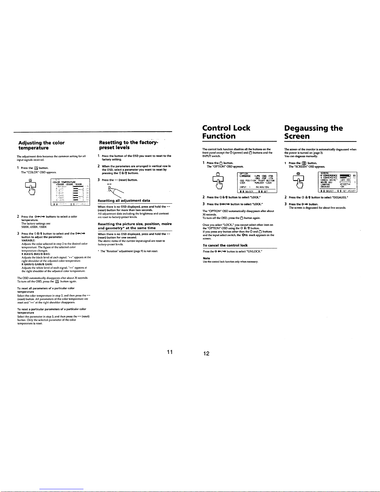
Sony GDM-90W01T5 User manual

CHASSIS
SERVICE MANUAL
SPECIFICATIONS
W1
AEP Model
Chassis No. SCC-K49B-A
COLOR GRAPHIC DISPLAY
GDM-90W01T5

GDM-90W01T5
– 2 –
POWER SAVING FUNCTION
This monitor is capable of three states of reduced power consumption. By sensing the absence of video signals and one or both sync signals
coming from the host computer, it will reduce power consumption as follows.
Recovery time
–
Approx. 3 sec.
Approx. 3 sec.
Approx. 10 sec.
–
Power consumption
≤200 W
≤140 W
≤15 W
≤8 W
0 W
Power consumption
state
1 Normal operation
2 Standby (1st state)
3 Suspend (2nd state)
4 Active-off (3rd state)
5 Power-off
upower indicator
Green on
Green on
Green on
Off
Off
@power saving indicator
Off
Orange on
Orange on
Orange on
Off
Failure
HV, +B failure
Horizontal/Vertical deflection failure, thermal
protector
ABL protector
Aging/Self Test
Power Saving LED
Off
Blink Amber
Blink Amber
Off
Power LED
Blink Amber
Off
Blink Amber
Amber (0.5 sec) →
Off (0.5 sec) →
Green (0.5 sec) →
Off (0.5 sec) →
DIAGNOSIS
Aging Mode: Video aging During Power Save, press “OPTION” Key for longer than 2 seconds.
Self Test: OSD color-bar indication During Power Save, press “CONTRAST+” Key for longer than 2 seconds.
Self Test: OSD All White indication During Poewr Save, press “COLOR” key for longer than 2 seconds.
PRIMARY MODE PRIMARY
MODE AT PRODUCTION MODE1 MODE2 MODE3 MODE4 MODE5 MODE6 MODE7 MODE8 MODE9
RESOLUTION 640 X 480 1280 X 1024 1600 X 1200 1920 X 1080 1920 X 1080 1600 X 1024 1920 X 1200 720 X 400 1920 X 1035
CLOCK 25.175 MHz 135.000 MHz 202.500 MHz 159.840 MHz 216.023 MHz 170.447 MHz 245.480 MHz 28.322 MHz 74.250 MHz
— HORIZONTAL —
H-FREQ 31.469 kHz 79.976 kHz 93.750 kHz 67.500 kHz 84.384 kHz 81.320 kHz 95.000 kHz 31.469 kHz 33.750 kHz
µsec µsec µsec µsec µsec µsec µsec µsec µsec
H. TOTAL 31.778 12.504 10.667 14.815 11.851 12.297 10.526 31.777 29.630
H. BLK 6.356 3.022 2.765 2.803 2.963 2.910 2.705 6.355 3.771
H. FP 0.636 0.119 0.316 0.200 0.222 0.188 0.261 0.636 0.593
H. SYNC 3.813 1.067 0.948 0.901 1.000 0.939 1.043 3.813 1.185
H. BP 1.907 1.837 1.501 1.702 1.741 1.784 1.401 1.907 1.993
H. ACTIV 25.422 9.481 7.901 12.012 8.888 9.387 7.821 25.422 25.859
— VERTICAL —
V. FREQ(HZ) 59.940 Hz 75.025 Hz 75.000 Hz 60.000 Hz 72.000 Hz 76.000 Hz 76.000 Hz 70.087 Hz 60.000 Hz
lines lines lines lines lines lines lines lines lines
V. TOTAL 525 1066 1250 1125 1172 1070 1250 449 562.5
V. BLK 45 42 50 45 92 46 50 49 45
V.FP 10113333125
V. SYNC 2 3 3 3 3 3 3 2 5
V. BP 33 38 46 39 86 40 44 35 35
V. ACTIV 480 1024 1200 1080 1080 1024 1200 400 517.5
— SYNC —
INT(G) NO NO NO NO NO NO NO NO NO
EXT(H/V)/POLARITY YES N/N YES P/P YES P/P YES N/N YES N/N YES N/N YES N/N YES N/P YES N/N
EXT(CS)/POLARITY NO NO NO NO NO NO NO NO NO
INT/NON INT NON INT NON INT NON INT NON INT NON INT NON INT NON INT NON INT INT
96.8.22 VER.
TIMING SPECIFICATION

GDM-90W01T5
–3 –
TABLE OF CONTENTS
Section Title Page
1. GENERAL................................................................... 4
2. DISASSEMBLY
2-1. Cabinet Removal ................................................. 11
2-2. D Board Removal ................................................ 11
2-3. G Board Removal ................................................. 12
2-4. A Board Removal ................................................. 12
2-5. M Board Removal ................................................ 13
2-6. L Board Removal ................................................. 13
2-7. Service Position .................................................... 14
2-8. Harness Location
(1) D Block Side ....................................................... 14
(2) G Block Side ....................................................... 15
2-9. H1, H2 and J Boards Removal............................. 15
2-10. Picture Tube Removal ......................................... 16
3. SAFETY RELATED ADJUSTMENT............. 17
4. ADJUSTMENTS ...................................................... 18
Section Title Page
5. DIAGRAMS
5-1. Block Diagrams ................................................... 21
5-2. Frame Schematic Diagram .................................. 27
5-3. Circuit Boards Location ...................................... 29
5-4. Schematic Diagrams and Printed Wiring Boards ... 29
(1) Schematic Diagram of D Board .......................... 33
(2) Schematic Diagrams of G, GA, GB and
J Boards ........................................................... 37
(3) Schematic Diagrams of H1, H2, L and
M Boards ......................................................... 41
(4) Schematic Diagram of A Board .......................... 45
5-5. Semiconductors ................................................... 52
6. EXPLODED VIEWS
6-1. Chassis ................................................................. 54
6-2. Picture Tube ........................................................ 55
6-3. Packing Materials ................................................ 56
7. ELECTRICAL PARTS LIST ............................ 57
WARNING!!
NEVER TURN ON THE POWER IN A CONDITION IN
WHICH THE DEGAUSS COIL HAS BEEN REMOVED.
SAFETY-RELATED COMPONENT WARNING!!
COMPONENTS IDENTIFIED BY SHADING AND MARK ¡
ON THE SCHEMATIC DIAGRAMS, EXPLODED VIEWS
AND IN THE PARTS LIST ARE CRITICAL FOR SAFE
OPERATION. REPLACE THESE COMPONENTS WITH
SONY PARTS WHOSE PART NUMBERS APPEAR AS
SHOWN IN THIS MANUAL OR IN SUPPLEMENTS
PUBLISHED BY SONY. CIRCUIT ADJUSTMENTS THAT
ARE CRITICAL FOR SAFE OPERATION ARE IDENTIFIED
IN THIS MANUAL. FOLLOW THESE PROCEDURES
WHENEVER CRITICAL COMPONENTS ARE REPLACED
OR IMPROPER OPERATION IS SUSPECTED.
Note: Hand degauss must be used on stand-by or power-off condition.
This model has an automatic earth magnetism correction function by using an earth
magnetism sensor and a LCC coil. When using a hand degauss while monitor (LCC
coil) is being operated, it sometimes gets magnetized, and the system may not work
properly as a result.

–4 –
SECTION 1
GENERAL
The operating instructions mentioned here are partial abstracts
from the Operating Instruction Manual. The page numbers of
the Operating Instruction Manual remein as in the manual.

–5 –

–6 –

–7 –

–8 –

–9 –

–10 –

–11 –
GDM-90W01T5
SECTION 2
DISASSEMBLY
2-1. CABINET REMOVAL
Top cover
Five screws
(+
-
BV tapping screw M4 x 8)
Nine screws
(+
-
BV tapping screw M4 x 8)
Video shield
Two screw covers (T)
Cabinet
Six screws
(+ BVTP 4 x 16)
1
2
3
4
6
7
8
9
Screw cover (S)
Screw cover (S)
5
2-2. D BOARD REMOVAL
Two screws
(+
-
BV tapping screw M4 x 6)
Two screws
(+ BVTP 3 x 10)
D board
Open the D block in the direction
of the arrow . and remove of
the arrow .
Two hooks
1
2
A
B
A
B
3
4

GDM-90W01T5
–12 –
2-3. G BOARD REMOVAL
Two screws
(+-BV tapping screw M4 x 6)
Two hooks
Two screws
(+BVTP 3 x 10)
Two screws
(+ P SW screw M3 x 10)
G shield
Two screws
(+BVTP 3 x 10)
G board
Open the G block in the direction
of the arrow . and remove of
the arrow .A
BTwo printed circuit board holders
A
B
1
2
3
4
5
6
7
8
2-4. A BOARD REMOVAL
A borad
Two screws
(+BVTP 3 x 10)
1
2

–13 –
GDM-90W01T5
2-5. M BOARD REMOVAL
2-6. L BOARD REMOVAL
Two screws
(+ BVTP Screw 3 x 8)
1
M board
2
Two claws
1
L board
2

GDM-90W01T5
–14 –
D block
G block
The D and G blocks are not widely
opened after the wires are properly
arranged, as shown in the figure.
2-7. SERVICE POSITION
D board (Refer to 2-2.)
Rear shield
D,G boards
A board (Refer to 2-4.)
G board
(Refer to 2-3.)
CAUTION : SHORT
If the claw is hooked,
opening and closing
the board is impossible.
Do not try to do it by force.
If the claw is hooked,
opening and closing
the board is impossible.
Do not try to do it by force.
2-8. HARNESS LOCATION
(1) D block side

–15 –
GDM-90W01T5
D block
G block
(2) G block side
2-9. H1, H2 AND J BOARDS REMOVAL
Four screws
(Tapping screw)
CN3001
CN3002
H1 board Two screws
(+ BVWHTP screw 3 x 12)
Bezel
5
6
7
8
2
Two screws
(+ BVTP 4 x 16)
1
H2 board
4
Two screws
(+ BVWHTP screw 3 x 12)
Claw
9J board
CN4001
3

GDM-90W01T5
–16 –
2-10.PICTURE TUBE REMOVAL
3When one side of the rubber cap is
separated from the anode button, the
anode-cap can be removed by turning
up the rubber cap and pulling up it in the
direction of the arrow c.
• HOW TO HANDLE AN ANODE-CAP
1Don’t hurt the surface of anode-caps with shartp shaped material!
2Don’t press the rubber hardly not to hurt inside of anode-caps!
A material fitting called as shatter-hook terminal is built in the
rubber.
3Don’t turn the foot of rubber over hardly!
The shatter-hook terminal will stick out or hurt the rubber.
a
b
c
Anode Button
•REMOVAL OF ANODE-CAP
NOTE: Short circuit the anode of the picture tube and the anode cap to the metal chassis, CRT shield or carbon painted on the CRT, after
removing the anode.
•REMOVING PROCEDURES
1Turn up one side of the rubber cap in
the direction indicated by the arrow a.2Using a thumb pull up the rubber cap
firmly in the direction indicated by the
arrow b.
Anode cap
Purse lock
Deflection yoke
Top cover
TOP VIEW
•INSTALLED POSITION OF THE ANODE-CAP
Install the anode cap as shown a figure.
Open the D blook
(Refer 2-2.)
CN6010
2P (NA)
Four screws
(+
-
BV tapping screw M4 x 8)
A board
Open the G blook
(Refer 2-3.)
Neck assy
Deflection yoke
Picture tube
Three connectors
1
2
3
4
5
6
7
8
Anode cap
2P (DY)
9

–17 –
GDM-90W01T5
HV Regulator
Circuit Check
HV Hold-Down
Circuit Check
Beam Current
Protector#1
Circuit Check
Beam Current
Protector#2
Circuit Check
Voltage of 3rd
winding of FBT
When replacing or repairing the shown below table, the
following operational checks must be performed as a
safety precaution against X-rays emissions from the unit.
a) HV Regulator Circuit Check
1) Confirm that the voltage of the pin !. of IC4202
on GB board is within the voltage range shown be-
low.
Standard: 9.00±0.10 V DC
b) HV Hold-Down Circuit Check
1) Using an external DC power supply, apply the
voltage shown below between cathode of D4220 on
G board and ground, and confirm that the HV Hold-
Down circuit works. (TV Raster disappears)
Check Condition: Less than 33.8 V DC
c) Beam Current Protector#1 Circuit Check
1) Record the initial regulation value of ABL-
SHUTDOWN and using a PC computer, input the
“255”for maximum value of resistor.
2) Connect to the Constant Current Jig (A) between pin
!] of T4202 (FBT) on G board and ground, and
confirm that the Beam Current Protector Circuit
works. (TV Raster disappears)
Check Condition: Less than 1.55 mA
d) Beam Current Protector#2 Circuit Check
Input the initial regulation value of ABL-SHUTDOWN
that was recorded c)-1).
1) Shorted between pin !] of IC4202 on GB board and
ground.
2) Connect to the Constant Current Jig (A) between pin
!] of T4202 (FBT) on G board and ground, and
confirm that the Beam Current Protector Circuit
works. (TV Raster disappears)
Check Condition: Less than 1.72 mA
e) Voltage of 3rd winding of FBT
1) Confirm that the voltage of the cathode of D4220 on
G board is within the voltage range shown below.
Satndard: More than 28.0 V DC
SECTION 3
SAFETY RELATED ADJUSTMENT
+0.0
–0.1
Part Replaced (])
GB board IC4202
•Mounted GB board
G board D4220
•Mounted G board
•Mounted GB board
G board D4204,D4206,D4220,
R4211,R4212,R4216,
R4219
•Mounted G board
GB board IC4202
•Mounted GB board
G board R4222, R4223
•Mounted G board
•Mounted GB board
G board T4202(FBT)
•Mounted G board
Check Condition
Input voltage : 100~120 V AC
Input signal : White dots or Cross Hatch
Controls : BRT and CONT →Minimum
B+ voltage : 193~201 V DC

GDM-90W01T5
– 18 –
SECTION 4
ADJUSTMENTS
9. Adjust the DY position and purity, and the DY tilt, and land-
ing of the center and 4 corners with the landing checker.
Note:
(1) Adjust in s non-magnetic field. BV=35uT.
(2) If adjusting in a magnetic fields, add the shift from the non-
magnetic field in your estimation.
<Specification>
Adjust the green of corners 1 to 4, and center 6 to ±5 µm, and red
and blue to within ±7 µm of green, and the difference between
red and blue to within ±10 µm.
Adjust the green of 5 and 7 to within ±10 µm, and red and blue to
within ±7 µm of green, and the difference between red and blue
to within ±10 µm.
(Set each corner to 1st frame of the crosshatch.)
10. For the up/down and left/right swing, swing the DY and in-
sert a wedge so that the up and down pins are equal at the top
and bottom and the horizontal trapezoid is equal at the left
and right. Insert the wedge firmly so that the DY does not
shake.
11. Check the landing of each corner, and if they do not satisfy
the specification, paste a Disk-Mg onto the funnel and ad-
just.
Note:
(1) Do not paste more than 2 magnets to one corner.
(2) Paste within 80 to 100 mm from the DY on the diagonal line
of the magnet.
(3) If using the magnet, be sure to demagnetize with the hand
degausser and check.
(4) If the specification cannot be satisfied though the adjustment
of 11 was made, the following adjustment may be made.
a) Adjust the “LCC xx” register that corresponds to the part
to be adjusted. (See the following figure)
Note :“LCC NS” =108~148
except for “LCC NS”=114~142
b) Execute the service saving.
“LCC LT” “LCC NS” “LCC RT”
“LCC LB” “LCC NS” “LCC RB”
(5) If performing a manual degaussing after adjustment of “LCC
xx”, set “LCC xx” to 128 (of “LCC SW” to 0).
(After degaussing, return the adjustment value to original
value.)
12. Remove the sensor and wobbling coil.
13. Switch the signal to R.G.B., and check that each color is
pure.
14. Check that the DY is not tilting, and fix the purity Mg with a
white pen.
zLanding Rough Adjustment
1. Enter the full white signal. (or the full black dots signal).
2. Adjust the contrast to the maximum.
3. Make the screen monogreen.
Note: Off the outputs from R ch and B ch of SG.
4. Adjust the brightness is easy to see with the G2 resistor.
5. Reverse the DY, and adjust coarsely the purity magnet so
that a green raster positions in the center of screen.
6. Moving the DY forward, adjust so that an entire screen be-
comes monogreen.
7. Adjust the tilt of DY, and fix lightly with a clamp.
zLanding Fine Adjustment
1. Put the set inside the Helmholtz coil.
2. Input the single green signal and set the CONT control to
MAX.
Note: Set to 1k=300 µA with the signal green signal, and after
aging for about 30 minutes, adjust so that it is exactly this
value.
3. Before making any adjustment, confirm that respective
preadjustment values of the registers listed below have
been entered correctly.
LCC K TEMP 100 LCC R TOL 128
LCC K EW C 105 LCC SW7 7
LCC K NS C 0 LCC TEMP 151
LCC K NS 160 LCC VX #
LCC K NS FOR ROT 64 LCC VY #
LCC K ROT FOR NS 46 LCC K VY NS 0
LCC K POL 255 LCC P TOL 128
LCC WO 128
#=Input values in time adjustments
Also, confirm that “LCC NS=LCC LT=LCC LB=LCC
RB=LCC RT=128”
4. Send the “LCC READ” command of the ECS.
If the ECS command cannot be used, execute the status read-
ing and VX, VY and V TEMP values may be entered to
“LCC VX”, “LCC VY” and “LCC TEMP” respectively.
5. Execute the service saving.
6. Demagnetize the metal part of the chassis with the hand de-
gausser and coil degausser, and the CRT surface with the
hand degausser.
Input AC 230V to AC IN, turn on and off the power to per-
form auto degaussing. (Perform auto degaussing by setting
“MON CON REG 2”=152. Return to the original value after
use.)
Demagnetize the CRT surface with the hand degausser
again.
Note: Hand degauss must be used on stand-by or power-off con-
dition.
This model has an automatic earth magnetism correction
function by using an earth magnetism sensor and a LCC
coil. When using a hand degauss while monitor (LCC coil)
is being operated, it sometimes gets magnetized, and the
system may not work properly as a result.
7. Attach the wobbling coil to the designated part of the CRT
neck.
8. Attach the sensor of the landing adjustment unit on the CRT
surface.
12
4
3
6
7
5

GDM-90W01T5
– 19 –
MODE
A
B
1,3
395 mm
296 mm
2
370 mm
296 mm
aB
Ab
4,5,8,9
474 mm
266 mm
6,7
474 mm
296 mm
MODE
a
b
4
3.0 mm
3.8 mm
other mode
4.4 mm
4.4 mm
Run the service software and then follow the instruction.
zConvergence SpecificationzConvergence Rough Adjustment
(1) Receive an image of the white crosshatch signals (white
lines on black).
(2) Place the protrusions of the 6-fold poles magnet attached to
the CRT neck upon each other.
(3) Make rough adjustment of the H direction convergence by
using H. STAT VR (left side of the video block).
(4) Make a rough adjustment of the V direction convergence by
using “V. STAT”.
Protrusions
60°
Fig. 1
Fig. 3
Set so that the protruding
parts of the 2 magnet rings
agree with each other.
TLV YCHYBH
RV801
A board
APH
XBV
XCVTLH
XBV XCV
B
R
RRBB
RBBR
H. AMP
H. TILT (TLH)YCH
RB
BR
YBH
R B
zWhite Balance Adjustment Specification
(1) 9300K
x = 0.283 ± 0.008
y = 0.298 ± 0.008
(2) 6500K
x = 0.313 ± 0.008
y = 0.329 ± 0.008
(3) 5000K
x = 0.346 ± 0.008
y = 0.359 ± 0.008
zVertical and Horizontal Position and Size
Specification
zFocus adjustment
Adjust the focus volume 1 and 2 for the optimum focus.
FOCUS2
FOCUS1
FBT
IBM AT Computer
as a Jig
1-690-391-21
1A-1500-819-A
Interface Unit
2
*The parts above ( ) are necessary for DAS adjustment.
13
D-sub
(9 Pin [female]) mini Din
(8Pin) 4 Pin
3-702-691-01
Connector Attachment
3
To BUS CONNECTOR
4 Pin 4 Pin
Purity 6-pole Mg
B
AA0.24 mm
B
72,3,4,5,6
0.32 mm
0.28 mm
0.36 mm
MODE 1,8,9
0.28 mm
0.40 mm
Fig. 2

GDM-90W01T5
–54 –
SECTION 6
EXPLODED VIEWS
•Items marked " * " are not stocked since
they are seldom required for routine
service. Some delay should be
anticipated when ordering these items.
6-1. CHASSIS
v7-685-647-79 +BVTP 3X10
s7-685-663-71 +BVTP 4X16
a7-682-548-04 +–BV TAPPING SCREW M3X8
NOTE:
•Items with no part number and no
description are not stocked because they
are seldom required for routine service.
•The construction parts of an assembled
part are indicated with a collation number
in the remark column.
REF.NO. PART NO. DESCRIPTION REMARKREF.NO. PART NO. DESCRIPTION REMARK
1 *X-4034-602-1 BEZEL ASSY 2, 3
2 *4-055-556-41 BUTTON, POWER
3 4-042-593-01 SPRING, COMPRESSION
4 *8-933-217-00 CONTROL BLOCK BOARD
(H1 BOARD,COMPLETE)
5 4-029-432-01 SCREW (3X12), (+) BVWHTP
6 *8-933-218-00 INPUT SW BOARD (H2 BOARD,
COMPLETE)
7 4-055-558-11 COVER, SLIDE SWITCH
8 *8-933-216-00 M BOARD, COMPLETE
9¡1-251-382-12 INLET, AC 3P (WITH NOISE FILTE)
10 4-052-345-01 SCREW, (3X8) (+K), TAPPING
11 4-055-730-01 LABEL, CONNECTOR
12 *8-933-200-00 VIDEO AMP MCB ASSY
(A BOARD, COMPLETE)
13 1-900-215-90 CONNECTOR ASSY
14 *1-777-729-31 CABLE, COAXIAL (B)
15 *1-777-729-21 CABLE, COAXIAL (G)
16 *1-777-729-11 CABLE, COAXIAL (R)
17 4-389-025-01 SCREW (M4) (EXT TOOTH WASHER)
18 4-381-962-11 SCREW (M4X8), TAPPING, (+-) (BV)
10
11
1
12
23
14
4
5
6
7
8
9
21 22
23
24
15
25
26
17
27
18
28
29
20
16
19
18
18
18
18
22 21
5
30
31 32
33 34
32
13
19 4-046-765-01 SCREW, TAPPING
20 *8-933-213-00 DEFLECTION MCB ASSY
(D BLOCK ASSY) 21, 22
21 *3-701-903-11 HOLDER, PRINTED CIRCUIT BOARD
22 *4-382-848-01 HOLDER, PRINTED CIRCUIT BOARD
23 ¡*X-4034-094-1 TRANSFORMER ASSY, FLYBACK
(NX-4202//J1D4)
24 *3-703-141-00 HOLDER, PRINTED CIRCUIT BOARD
25 4-382-854-11 SCREW (M3X10), P, SW (+)
26 ¡*8-933-220-00 POWER BLOCK MCB (GA BOARD,
COMPLETE)
27 ¡*8-933-221-00 POWER BLOCK MCB (GB BOARD,
COMPLETE)
28 ¡*8-933-219-00 POWER BLOCK ASSY (G BLOCK
ASSY) 21~27
29 X-4034-379-1 COVER, TOP
30 *4-055-731-01 SHIELD, VIDEO
31 *4-055-559-41 CABINET
32 *4-055-563-41 COVER (S), SCREW
33 *4-055-562-41 COVER (T), SCREW
34 *4-059-245-01 LABEL, INFORMATION
The components identified by shading
and mark !are critical for safety.
Replace only with part number specified.
Table of contents
Other Sony Monitor manuals

Sony
Sony FW-85BZ40L User manual

Sony
Sony JumboTron LDU-1530S User manual

Sony
Sony GDM-17SE2T5 User manual

Sony
Sony TRINITRON BVM-20F1U User manual

Sony
Sony PFM-50C1 User manual

Sony
Sony ELF-SR2 User manual

Sony
Sony SDM-S51 User manual

Sony
Sony FD Trinitron GDM-FW900 User manual

Sony
Sony Trinitron PVM-2950QM User manual

Sony
Sony SDM-S75NB User manual

Sony
Sony LMD-2735MD User manual

Sony
Sony Trinitron BVM-D32E1WA User manual

Sony
Sony LT10 Series User manual

Sony
Sony GDM-17SE2T User manual

Sony
Sony Trinitron HMD-A240 User manual

Sony
Sony CPD-2001G User manual

Sony
Sony Trinitron BVM-F24E User manual

Sony
Sony PVM-14L1 User manual

Sony
Sony Trinitron CPD-E500 User manual

Sony
Sony PFM-32C1 User manual