manuals.online logo
Brands
  1. Home
  2. •
  3. Brands
  4. •
  5. Sony
  6. •
  7. Monitor
  8. •
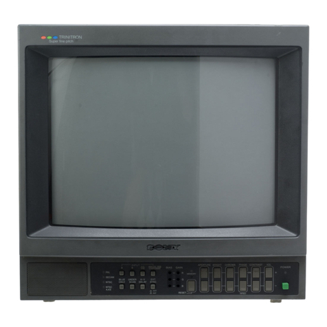
  9. Sony Trinitron PVM-4300 User manual

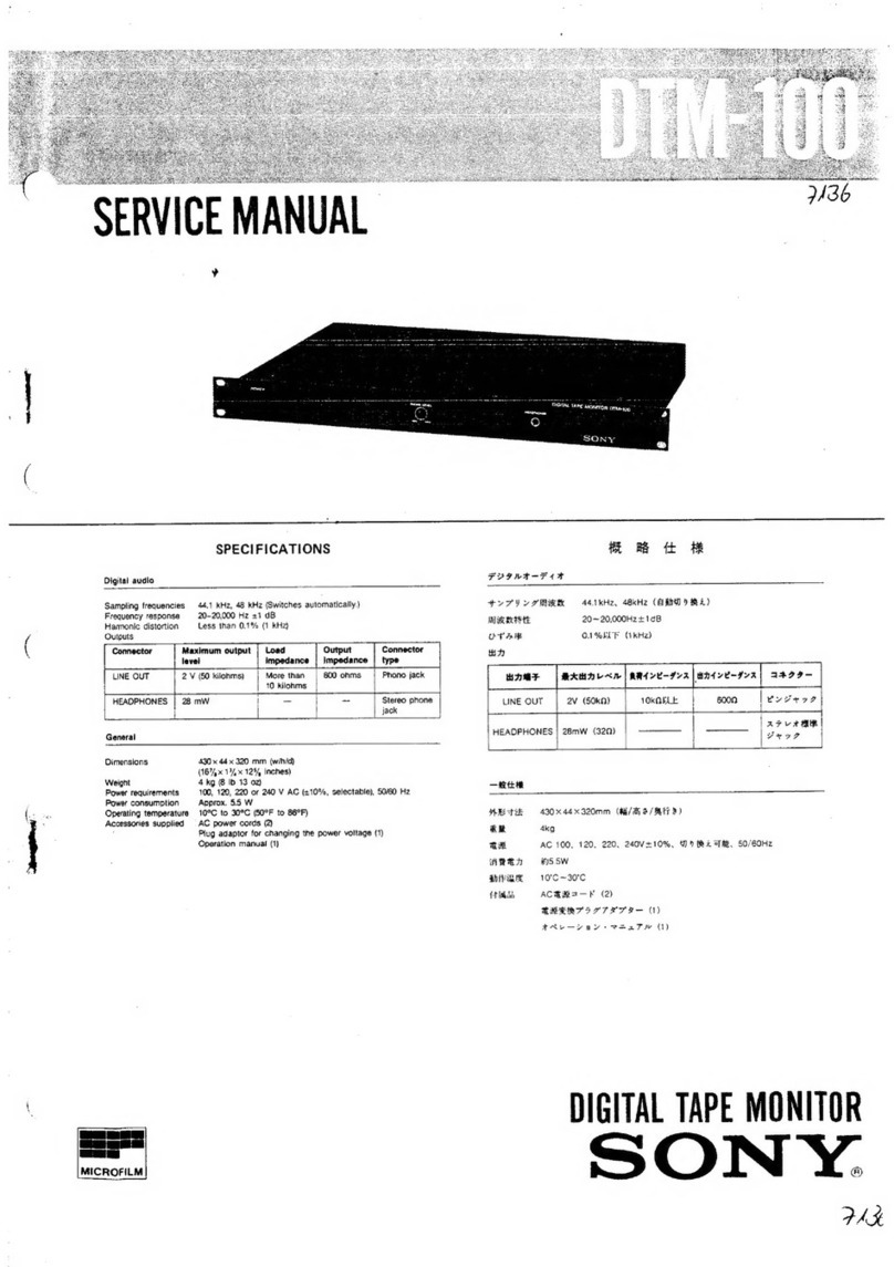
Sony Trinitron PVM-4300 User manual

Other manuals for Trinitron PVM-4300

1

Other Sony Monitor manuals

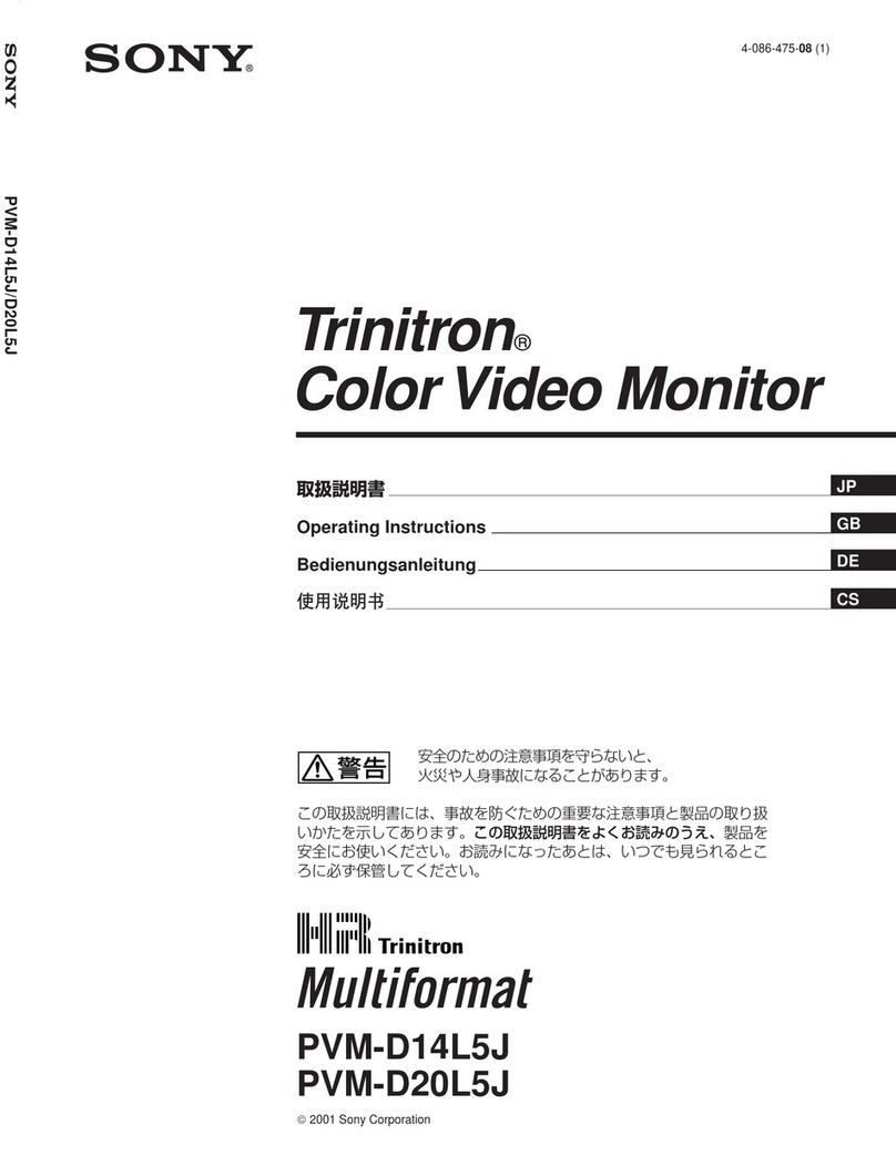
Sony LMD-XH550MD User manual

Sony

Sony LMD-XH550MD User manual

Sony LMD1750W User manual

Sony

Sony LMD1750W User manual

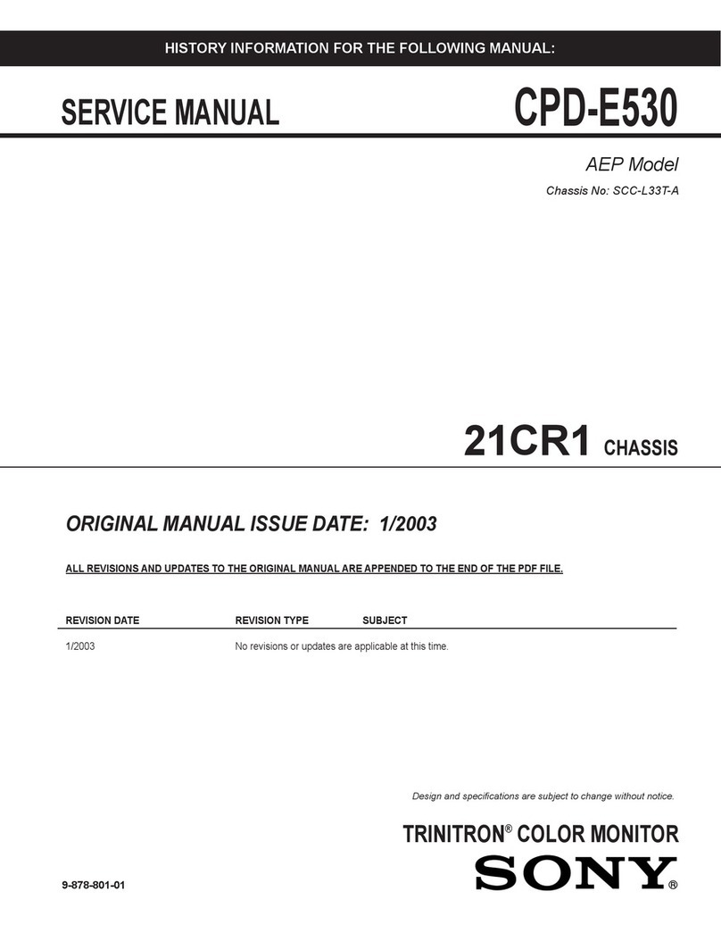
Sony SDM-S75NB User manual

Sony

Sony SDM-S75NB User manual

Sony SDM-S81 User manual

Sony

Sony SDM-S81 User manual

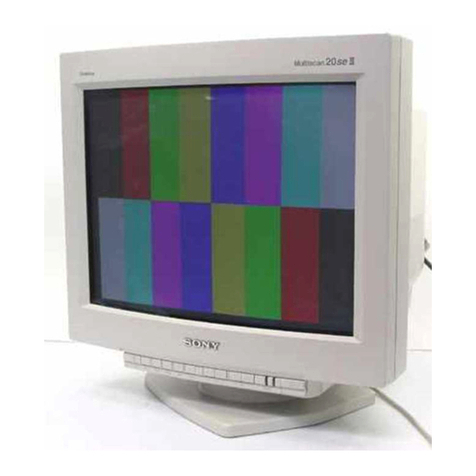
Sony VAIO CPD-100VS User manual

Sony

Sony VAIO CPD-100VS User manual

Sony Trinitron PVM-8041Q User manual

Sony

Sony Trinitron PVM-8041Q User manual

Sony PFM-50C1 User instructions

Sony

Sony PFM-50C1 User instructions

Sony Trinitron CPD-G200 User manual

Sony

Sony Trinitron CPD-G200 User manual

Sony BRAVIA FW-65EZ20L User manual

Sony

Sony BRAVIA FW-65EZ20L User manual

Sony SDM-V72W User manual

Sony

Sony SDM-V72W User manual

Sony Multiscan SDM-M61 User manual

Sony

Sony Multiscan SDM-M61 User manual

Sony XVM-R70 - Monitor User manual

Sony

Sony XVM-R70 - Monitor User manual

Sony FWD-40LX1 User manual

Sony

Sony FWD-40LX1 User manual

Sony PFM-42V1A User manual

Sony

Sony PFM-42V1A User manual

Sony PVM-2541 PVM-1741 PVM-740 LMD-2451W LMD-1751W LMD-4251TD LMD-2451TD LMD-2341W LMD-2041W LMD-1541W LMD-940W LMD-1530W LMD-2110W... User manual

Sony

Sony PVM-2541 PVM-1741 PVM-740 LMD-2451W LMD-1751W LMD-4251TD LMD-2451TD LMD-2341W LMD-2041W LMD-1541W LMD-940W LMD-1530W LMD-2110W... User manual

Sony XVM-R75 User manual

Sony

Sony XVM-R75 User manual

Sony LMD-3250MD User manual

Sony

Sony LMD-3250MD User manual

Sony FWD-40LX2F Operating Instructions (Base... User manual

Sony

Sony FWD-40LX2F Operating Instructions (Base... User manual

Sony PVM-9L1 User manual

Sony

Sony PVM-9L1 User manual

Sony Trinitron HMD-A400 User manual

Sony

Sony Trinitron HMD-A400 User manual

Sony LMD-1410/1420 User manual

Sony

Sony LMD-1410/1420 User manual

Sony FWD-40LX2F Operating Instructions (Base... User manual

Sony

Sony FWD-40LX2F Operating Instructions (Base... User manual

Sony NTM-910 User manual

Sony

Sony NTM-910 User manual

Sony LMD-1510W User manual

Sony

Sony LMD-1510W User manual

Popular Monitor manuals by other brands

Samsung ME32C user manual

Samsung

Samsung ME32C user manual

ViewSonic VA926-LED user guide

ViewSonic

ViewSonic VA926-LED user guide

Furuno Mu 120c Operator's manual

Furuno

Furuno Mu 120c Operator's manual

Asus VB171D - 17" LCD Monitor Service manual

Asus

Asus VB171D - 17" LCD Monitor Service manual

AOC 9GLR Technical specifications

AOC

AOC 9GLR Technical specifications

DMG RAFFAELLO manual

DMG

DMG RAFFAELLO manual

AOC LM720 - 17" Technical specifications

AOC

AOC LM720 - 17" Technical specifications

Memorex MT1701 user guide

Memorex

Memorex MT1701 user guide

ViewSonic VE510s-4 Service manual

ViewSonic

ViewSonic VE510s-4 Service manual

Farenheit T-1503CM instruction manual

Farenheit

Farenheit T-1503CM instruction manual

Ditel DINOS DN129/AT Quick installation guide

Ditel

Ditel DINOS DN129/AT Quick installation guide

Kenwood DMX1025BT quick start guide

Kenwood

Kenwood DMX1025BT quick start guide

Dell S2409WFP user guide

Dell

Dell S2409WFP user guide

EverFocus EN-7517E instruction manual

EverFocus

EverFocus EN-7517E instruction manual

Dell P3222QE user guide

Dell

Dell P3222QE user guide

Panasonic TH152UX1 - 152" PLASMA TV Service manual

Panasonic

Panasonic TH152UX1 - 152" PLASMA TV Service manual

LG 50PM1M -  - 50" Plasma Panel Service manual

LG

LG 50PM1M - - 50" Plasma Panel Service manual

Asus VW247H user guide

Asus

Asus VW247H user guide

manuals.online logo
manuals.online logoBrands
  • About & Mission
  • Contact us
  • Privacy Policy
  • Terms and Conditions

Copyright 2025 Manuals.Online. All Rights Reserved.

SONY, 3-750-840-21 (1)
Trinitron® Color Video Monitor
PVM-4300
Operating Instructions page 2
Before operating the unit, please read this manual thoroughly
and retain it for future reference.
Mode d’emploi page 30
Avant la mise en service de cet appareil, priere de lire attentivement
ce mode d'emploi que Ton conservera pour toute reference uiterieure.
*U. tlrl
<. t1•
*>
ffiSr.qvj'
£
Sal
Owner’s Record
The model and serial numbers are located on the rear.
Record the serial number in the space provided below.
Refer to these numbers whenever you call upon your Sony
dealer regarding this product.
Model No. PVM-4300 Serial No
<§> 1989 by Sony Corporation
WARNING
To prevent fire or shock hazard, do not ex-
pose the unit to rain or moisture.
This symbol is intended to alert the
user to the presence of uninsulated
“dangerous voltage" within the prod-
uct's enclosure that may be of suffi-
cient magnitude to constitute arisk of
electric shock to persons.
This symbol is intended to alert the
user to the presence of important
operating and maintenance (servicing)
instructions in the literature accompa-
nying the appliance.
For the customers in the USA
INFORMATION
This equipment generates and uses radio frequency energy
and if not installed and used properly, that is, in strict accor-
dance with the manufacturer’s instructions, may cause inter-
ference to radio and television reception. It has been type
tested and found to comply with the limits for aClass B
computing device in accordance with the specifications in
Subpart Jof Part 15of FCC Rules, which are designed to
provide reasonable protection against such interference in a
residential installation. However, there is no guarantee that
interference will not occur in aparticular installation. If this
equipment does cause interference to radio or television re-
ception, which can be determined by turning the equipment off
and on ,the user is encouraged to try to correct the interference
by one or more of the following measures:
Reorient the receiving antenna
Relocate the equipment with respect to the receiver
Move the equipment away from the receiver
Plug the equipment into adifferent outlet so that equipment
and receiver are on different branch circuits.
If necessary, the user should consult the dealer or an experi-
enced radio/television technician for additional suggestions.
The user may find the following booklet prepared by the
Federal. Communications Commission helpful:
“How to Identify and Resolve Radio-TV Interference Prob-
lems".
This booklet is available from the US. Government Printing
Office, Washington, DC 20402, Stock No. 004-000-00345-4.
For the customers in Canada
This apparatus complies with the Class Blimits for radio
noise emissions set out in Radio Interference Regulations.
2
Contents Precautions
Features 3
Precautions 3
Location and function of parts and controls 4
Installation 10
System connections 1
1
Viewing the picture from avideo equipment 17
Watching TV programs 17
Monitoring an analog RGB signal 18
Adjusting the picture and sound 18
Using the programmable remote commander 21
Specifications 28
Features
This color monitor features a45 "black TORINITRONs
picture tube for ahigh resolution,high contrast picture.
IDTV(improved definition TV) realized by various digital
technologies such as non-interlace and three-
dimensional comb filter,etc.
In addition, the following analog circuits are employed:
•Auto cut-off circuit keeps the color temperature(tint) of
the picture for the most pleasing color.
•Colorpure Filter™ (CCD) produces fine picture detail
without color spill or color noise.
•New Dynamic picture™ system adjusts picture contrast
automatically to produce more detail in both bright and
dark area of every scene.
Other convenient features
•SVIDEO IN jack which is connected to the Svideo output
jack on the VTR allows superior playback pictures.
•RGB connectors to connect amicrocomputer for
displaying the characters and color graphics.
•The programmable remote commander allows you to
operate video equipment made by Sony or other
manufacturers.
Safety
•Operate the unit only on 120 VAC.
•One blade of the plug is wider then the other for purpose
of safety and will fit into the power outlet only one way.
If you are unable to insert the plug fully into the outlet,
contact your dealer.
•Should any liquid or solid object fall into the cabinet,
unplug the unit and have it checked by qualified personnel
before operating it any further.
•Unplug the unit from the wall outlet if it is not going to be
used for several days or more. To disconnect the cord,
puli it out by the plug. Never pull the cord itself.
Installation
•To prevent internal heat build-up, do not block the
ventilation openings.
•Do not install the unit in ahot or humid place or in aplace
subject to excessive dust or mechanical vibration.
Cleaning
Clean the unit with aslightly damp soft cloth. Use amild
household detergent. Never use strong solvents such as
thinner or benzine as they might damage the finish of the
cabinet.
Repacking
Retain the original carton and packing materials for safe
transport of this unit in the future.
If you have any questions about this unit, contact your
authorized Sony dealer.
3
-ID RGB INPUT MODE selector
]=H
3
I
£—
EWIRELESS ON/OFF-^
switch
DWIRED IN ON/OFF
switch
EMANUAL ON/OFF switch
ECOLOR TEMP selector
—
El VHOLD control— —
ESTILL button —
—HH VOLUME control
buttons
jH PICTURE control
buttons
v@RGB button
-® VIDEO 1,2, 3buttons
®RESET button
EPicture adjustment buttons
4
[3 STANDBY indicator
Illuminates when the power is turned off by the remote
commander and the unit is set in the standby mode.
[T] POWER indicator
Illuminates when the power is turned on.
0Remote control detector
The beam from the remote commander is received here.
0POWER switch
Press this switch to turn on the monitor.
Press it again to turn off the monitor.
0RGB INPUT MODE selector
Set to 31 .5 kHz when connecting an equipment with 31 .5
kHz horizontal frequency to the RGB (31 .5 kHz) input
connector. Otherwise, set to 15.75 kHz,
0WIRELESS ON/OFF switch
Normally set to ON. Set to OFF so that the remote
control detector does not accept the beam from the
remote commander.
0WIRED IN ON/OFF switch
Normally set to ON, and the control Ssignal can be input
to the monitor. Set to OFF not to input the control S
signal to the monitor.
0MANUAL ON/OFF switch
Normally set to ON. Set to OFF so that the all controls
and buttons on the front panel cannot be operated.
0COLOR TEMP (temperature) selector
Use this selector to adjust the color temperature.
0VHOLD (vertical hold) control
When the picture rolls vertically, correct it with this
control.
0STILL button
Press this button to view the still picture. Press this
button again to restore the normal picture.
OH VOLUME control buttons
Press +to raise the volume or -to lower it.
jo] PICTURE control buttons
Press +to increase the contrast or -to decrease it.
0RGB button
Press this button to monitor the signal fed through the
RGB input connectors to the monitor.
®VIDEO 1,2, 3buttons
Press each button to select the VTR connected to the
respective VIDEO 1, 2, 3connector.
0RESET button
Press this button to reset picture and sound adjustments
to the factory preset level.
0Picture adjustment buttons
BALANCE control buttons
Press Lto increase the sound volume ot the left speaker
or Rto increase the sound volume of the right speaker.
BASS control buttons
Press +to increase the bass (low tone) or -to decrease
it.
TREBLE control buttons
Press +to increase the treble (high tone) or -to
decrease it.
SHARP (sharpness) control buttons*
Press +to obtain asharp picture or -to obtain aless
sharp picture.
BRIGHT (brightness) control buttons
Press +to make the picture brighter or -to make it
darker.
COLOR control buttons*
Press +to make the color intensity vivid or -to make it
darker.
HUE control buttons*
Press G(green) to make the skin tones greenish or R
(red) to make it purplish.
*These buttons have no effect on the picture fed through the
RGB (31 5kHz) connectors.
5
Q3 CONTROL Sconnectors-
LEVEL selector
-[|T| AUDIO OUT L/R jacks
[is] VIDEO 1,2, 3Sconnectors and 750
ON/OFF switches SPEAKER OUT (8-160)
L/R terminals
®‘© ©©©© ;i
;,,nnj£==:
iii 1 i1JSKjaifc asu mu, a
VIDEO 1, 2, 3connectors and 750
ON/OFF switches, and AUDIO jacks
AC IN connector
RGB (31.5 kHz) input connectors and -
SYNC ON GREEN switch
RGB (15.75 kHz) input connectors and
SYNC ON GREEN switch
6
g] CONTROL SIN/OUT connectors (mini-jack)
Connect to the CONTROL Sconnectors of aVTR or
several monitors.
It is then possible to control the system with asingle
remote commander.
OH VIDEO IS, VIDEO 2S, VIDEO 3S connectors
(4-pin DIN)
IN: Connect to the VTR with an SVIDEO output
connector.
OUT: Connect to the SVIDEO input connector of another
monitor.
750 (termination) ON/OFF switches
Normally set to ON.
When the OUT connector is connected to another
monitor to view the same picture on several monitors
(loop-through connection), set the switch to OFF.
HLEVEL selector
Set to VARIABLE to change the volume and tone quality
with the buttons on the monitor or the remote
commander.
Set to FIXED to keep the volume and tone quality at a
certain level.
@AUDIO OUT L/R jacks (phono jack)
When listening to the sound through an audio equipment,
connect to the audio inputs of an amplifier.
[22]SPEAKER OUT (8-160) L/R terminals
Connect to speakers with 8to 16 ohms impedance.
gVIDEO 1,VIDEO 2, VIDEO 3connectors (BNC type)
IN: Connect to the VTR with video output connector.
OUT: Connect to the video input connector of another
monitor.
AUDIO IN/OUT connectors (phono jack)
Connect lo the audio input/output connectors of aVTR or
amonitor.
750 (termination) ON/OFF switches
Same as that of [»].
0RGB (31.5 kHz) input connectors (BNC type)
Connect to an equipment with 31 .5 kHz horizontal
frequency.
SYNC ON GREEN switch
Set to ON to synchronize with the sync signal on G-
signal.
Set to OFF to synchronize with H/V sync signal or
composite sync signal.
gAC IN connector
Connect to an outlet using the supplied AC power cord.
0RGB (15.75 kHz) input connectors (BNC type)
Connect to amicrocomputer, etc. with analog RGB
output.
SYNC ON GREEN switch
Same as that of [0.
7
Location and Function of Parts and Controls
Programmable Commander RM-778
RESET button
SELECT button
LEVEL buttons
POWER button
RGB button
INPUT DISPLAY button
MTS button
STILL button
Battery installation
Insert the supplied four size “AA” batteries (IEC
designation R6) with the correct polarity.
Notes
•In normal operation, batteries will last up to half a
year. It the unit does not operate properly, the
batteries might be exhausted. Replace all with new
ones.
»To avoid damage from possible battery leakage,
remove the batteries for extended unused periods.
>Be sure that there are no obstructions between the
commander and the TV.
Operable range is limited.
The shorter the distance between the commander
and the unit, the wider the angle within which the
commander can control the unit.
8
(D Buttons used for other equipment than this unit
See "Using the programmable remote commander”
(page 21 )for operation of these buttons.
[a] MUTING button
Press this button to mute the sound.
Press this button again to restore the sound.
[H TV/VIDEO selector
Used for Sony TV or color TV tuner.
Press to change from the TV picture to the video picture,
or from the video picture to the TV picture.
[30]VIDEO 1, 2, 3selector
Press each button to select the equipment connected to
the respective VIDEO 1,2,3 connector.
[|T] Channel number buttons
Used for Sony TV or color TV tuner.
Press number buttons and ENTER when selecting
channel directly.
Press DISPLAY to turn on or off the channel display.
[5!PICTURE buttons
Press +to increase the picture contrast, or -to decrease
it.
[5! VOL (volume) buttons
Press +to raise the volume, or -to lower it.
[34] CH (channel) scan buttons
Press +to scan preset channels of higher numbers, or -
to scan preset channels of lower numbers.
|H RESET button
Press this button to reset the picture and sound
adjustments to the factory preset level.
I) SELECT button
Used for selecting the item to be adjusted.
13 LEVEL buttons
Press +(R) or -(L) to adjust the item or sound selected
with the SELECT button.
[»] POWER button
Press this button to turn on the monitor.
Press it again to turn off the monitor.
aRGB button
Press this button to monitor the signal fed through the
RGB input connectors.
@INPUT DISPLAY button
Press to indicate the input source on the screen, such as
VIDEO 1,2, 3, or RGB.
[«T] MTS (Multichannel TV Sound) button
Press this button to select MAIN, SAP (Second Audio
Program), or MONO of the Multichannel TV Sound
program.
[u] STILL button
Press this button to view the still picture.
Press it again to restore the normal picture.
9
Installation
Precautions on Installation
•Connect the AC IN connector on the rear of the unit to an •In order to prevent accidents resulting from unstable
outlet with the supplied AC power cord. installation, or in emergencies such as earthquakes,
•After installation, or when the monitor has been moved, or please consult your Sony representative.
when its direction has been changed, beam landing •Do not place a magnetized object, such as speakers,
adjustment is required. Please consult your Sony steel frames, etc., near the unit. Doing so may cause
representative. uneven color.
•This unit weighs approximately 200 kg (440 lb 15 oz). •Leave sufficient open space behind the unit for connecting
Make sure that the floor is strong enough. aVTR, etc.
I