– 3 –
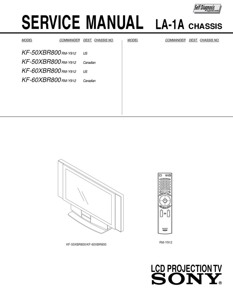
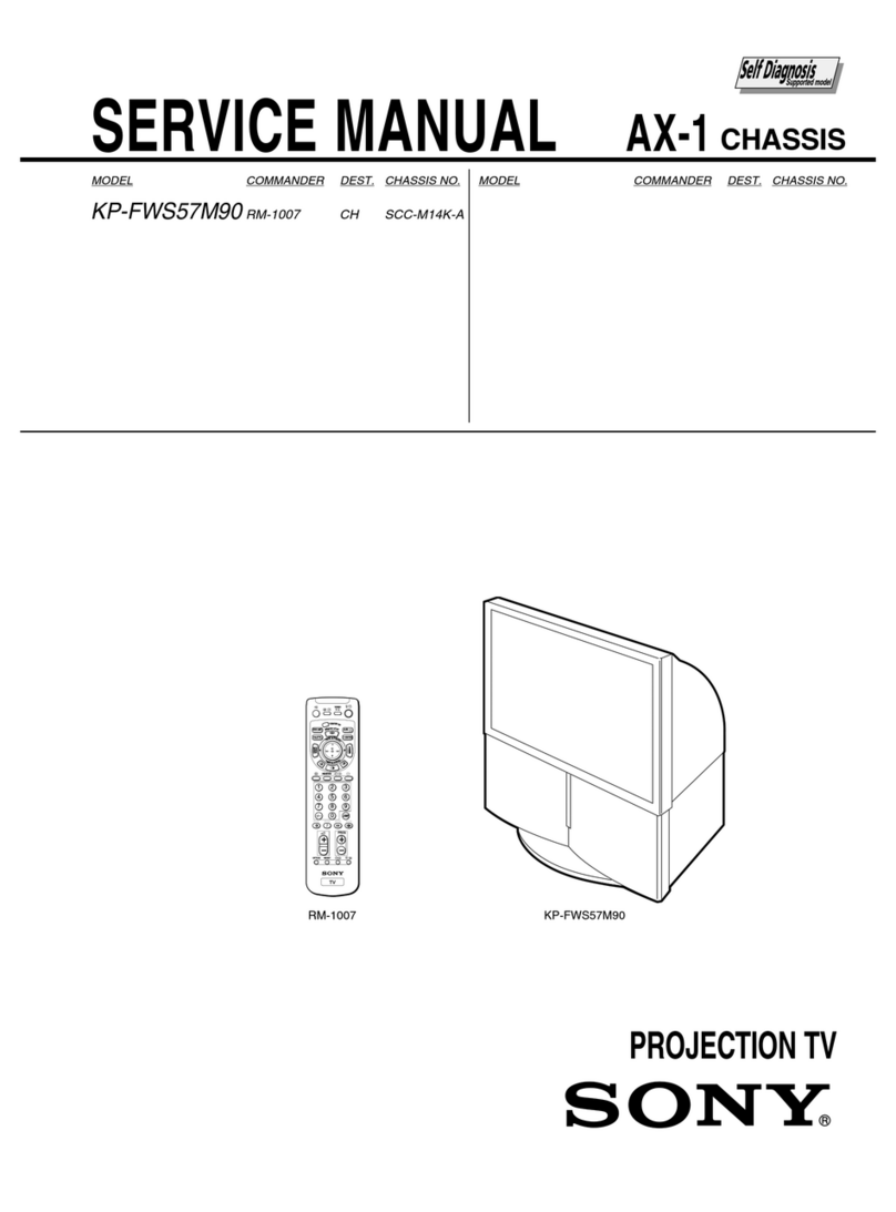
KP-ES43HK1/ME1/MN1/SN1, ES48HK1/ME1/MN1/SN1,
ES53HK1/ME1/MN1/SN1, ES61HK1/ME1/MN1/SN1K
RM-961
1. SELF DIAGNOSIS FUNCTION
1-1. Diagnostic Test Indicators ................................. 5
1-2. Display of STANDBY/TIMER
Light Flash Count............................................... 6
1-3. Stopping the STANDBY/TIMER Flash ............ 6
1-4. Self-Diagnostic Screen Display ......................... 7
1-5. Handling of Self-Diagnostic
Screen Display.................................................... 7
1-6. Self-Diagnostic Circuit ...................................... 8
2. GENERAL ................................................................. 9
3. DISASSEMBLY
3-1. Rear Board Removal ......................................... 33
3-2. Main Bracket Block Removal ........................... 34
3-3. Service Position ................................................. 34
3-4. Control Panel Block and Resistor Assembly
(Focus Pack) Removal ...................................... 35
3-5. Beznet Block Removal ...................................... 36
3-6. Chassis Block Removal...................................... 37
3-7. Terminal Board Removal ................................... 38
3-8. BD, DS, D Boards Removal .............................. 38
3-9. G, G1 Board Removal ........................................ 39
3-10. J1, B3, E, M1 Boards Removal.......................... 39
3-11. A1 Board Removal............................................. 40
3-12. High-Voltage Cable Removal and Installation.. 40
3-13. Picture Tube Removal........................................ 40
4. SET-UP ADJUSTMENTS
4-1. Screen Voltage Adjustment
(Rough Alignment) ........................................... 41
4-2. Screen (G2) Adjustment .................................... 41
4-3. Focus Rough Adjustment .................................. 41
4-4. Deflection Yoke Tilt Adjustment ...................... 41
4-5. 2-Pole Magnet Adjustment ................................ 42
4-6. 4-Pole Magnet Adjustment ................................ 42
4-7. Green, Red and Blue Focus Adjustment
4-7-1. Green, Red and Blue Lens Focus
Adjustment .................................................... 42
4-7-2. Green, Red and Blue Electrical Focus
Adjustment .................................................... 42
5. SAFETY RELATED ADJUSTMENT
5-1. HV Hold-Down Adjustment ............................. 43
TABLE OF CONTENTS
6. ELECTRICAL ADJUSTMENTS
6-1. Adjustments with Commander
6-1-1. How to Select Each Mode ............................. 44
6-1-2. How to Enter Service Mode .......................... 45
6-1-3. Method of Cancellation
from Service Mode ........................................ 45
6-1-4. How to Adjustments ...................................... 45
6-1-5. How to Write the Data ................................... 45
6-1-6. Memory Write Confirmation Method ........... 45
6-2. Service List ......................................................... 46
6-3. Picture Quality Adjustment
6-3-1. Preparation ..................................................... 60
6-3-2. NTSC Video Input ......................................... 60
6-3-3. NTSC RF Input .............................................. 61
6-3-4. PAL Video Input ............................................ 61
6-3-5. PAL RF Input................................................. 62
6-4. Color Offset (53, 61 inch model only)
6-4-1. 50 Hz (PAL) TV Mode .................................. 62
6-4-2. 50 Hz (PAL) Video Mode ............................. 62
6-4-3. 60 Hz (NTSC) TV Mode ............................... 62
6-4-4. 60 Hz (NTSC) Video Mode........................... 62
6-5. Registration Adjustment
6-5-1. Setup for Adjustment ..................................... 63
6-5-2. Method of Main Deflection Adjustment ....... 63
6-5-3. Operation Method
for Projector Engine (PJE) Mode .................. 64
6-5-4. Method of Projector Engine Adjustment
(Sub Deflection Adjustment)......................... 65
6-5-5. Deflection Adjustment ................................... 67
6-6. Auto Convergence Setting ................................. 73
6-7. White Balance Adjustment ................................ 73
6-8. Auto Convergence Error Code List ................... 74
Section Title PageSection Title Page
