1
Features
Overview
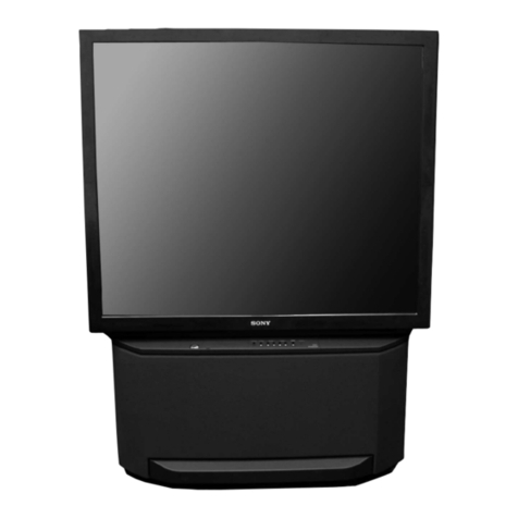
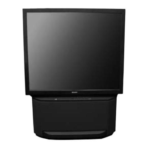
The models covered by this manual are the new KP53XBR200 and the
KP61XBR200. These two models are electrically identical. The differ-
ences have to do with screen size. Therefore they use different cabinets,
screens, mirrors and tubes. These sets also have a Self Diagnostic sys-
tem.
Picture
The two models share the following picture features:
··
··
·Advanced Pro-Optic System – Sony technology that allows full cor-
ner to corner focusing.
··
··
·New Extended Definition CRT – Allows corner to corner focusing to
be increased by 25% over last year’s model.
··
··
·MICROFOCUS Lens System
··
··
·Digital Reality Creation (DRC) – DRC uses line doubling and pat-
tern recognition algorithms to take the NTSC signal to a near HDTV
equivalent. This will be discussed in more detail later.
··
··
·Double Scan Technology
··
··
·Auto Focus Full Digital Convergence – Allows the setting of V and
H center and skew by the customer. This convergence system can
produce a sharper picture and is less susceptible to drift due to aging
or shipment.
··
··
·High Performance Video Processor
··
··
·3D Digital Comb Filter
··
··
·Brightview Dual Component Screen – The screen contains a Thin
Film Fresnel that brightens and sharpens the picture, and a Fine Pitch
Lenticularscreenthatachieves higherresolution byusing blackstripes
to increase contrast.
··
··
·Built-in High Contrast Screen
··
··
·First Surface Mirror – Unlike most mirrors, the reflective surface is
on the front of the mirror glass. This improves brightness and con-
trast, and eliminates ghosting caused by the reflected light passing
through the glass.
··
··
·Advanced Velocity Modulation
··
··
·Advanced High Voltage Regulation – Eliminates distortion and fo-
cus fluctuations that occur when changes in brightness levels cause
changes in the high voltage.
··
··
·Noise Reduction
··
··
·Shading Compensation – Eliminates color shift and hot spots that
can occur due to the angle of the picture tubes to the mirror.
··
··
·Wideband Video Amplifier
··
··
·Multi Image Driver – Digital-editing technology that provides versatil-
ity in controlling on-screen images. Used in Picture and Picture and
Channel Index modes.
··
··
·Twin View Picture-in-Picture – Allows for viewing two pictures si-
multaneously and the ability to expand either image up to double its
normal size.
··
··
·Free Layout Picture-in-Picture –Allowsthe PIPwindow tobe placed
anywhere on the screen.
··
··
·XDS (Extended Data Service) – Receives data information services
that some stations may broadcast. This data includes time, station
call letters, etc.
Audio
The two models share the following audio features:
··
··
·MTS Stereo with dbx NR
··
··
·Dolby Pro Logic Surround Sound
··
··
·Front Left/Right Audio Power - 20Wx2
··
··
·Center Audio Power – 20W
··
··
·Surround Audio Power – 15Wx2
··
··
·Center speaker input for use with a separate Dolby Pro Logic A/
V Reciever
