Sony SRS-T88 - Speaker - 4 Watt User manual

SRS-T88
US Model
Canadian Model
Tourist Model
SERVICE MANUAL
ACTIVE SPEAKER SYSTEM
SPECIFICATIONS
Ver 1.0 2004. 01
Sony Corporation
Personal Audio Company
Published by Sony Engineering Corporation
9-961-531-01
2004A1678-1
© 2004.01
Speaker section
Enclosure type Full range, Bass reflex,
magnetically shielded
Speaker system 34 mm (diameter)
Impedance 8 Ω
Rated input power 2 W
Maximum input power 3 W
Amplifier section
Rated output 2 W + 2 W
(10% T.H.D., 1 kHz, 8 Ω)
Bass boost MEGA BASS
Input Input cord a stereo-mini plug
(40 cm) ×1
Input impedance 4.7 kΩ(at 1 kHz)
General
Power Four R6 (size AA) batteries, DC
6 V (supplied AC power
adaptor)
Dimensions (w/h/d) approx. 198 ×75 ×36 mm
(7
7
/
8
×3 ×1
7
/
16
inch)
(during use)
Mass approx. 350 g (12 oz.) including
batteries
Supplied accessories
Carrying Pouch (1)
AC power adaptor (1)
Operating Instructions (1)
Plug adaptor * (1)
* For Tourist model, on sale in Japan only.
Battery life (5 mW + 5 mW output)
Battery type Usage time
Sony alkaline battery LR6 (SG) Approx. 30 hours*
Sony manganese battery R6 Approx. 15 hours*
*Usage time stated above may vary according to the
temperature or conditions of use.
Design and specifications are subject to change without
notice.

2
SRS-T88
TABLE OF CONTENTS
Flexible Circuit Board Repairing
•Keep the temperature of soldering iron around 270˚C
during repairing.
•Do not touch the soldering iron on the same conductor of the
circuit board (within 3 times).
•Be careful not to apply force on the conductor when soldering
or unsoldering.
Notes on chip component replacement
•Never reuse a disconnected chip component.
•Notice that the minus side of a tantalum capacitor may be dam-
aged by heat.
1. SERVICING NOTES ······················································· 3
2. GENERAL ·········································································· 4
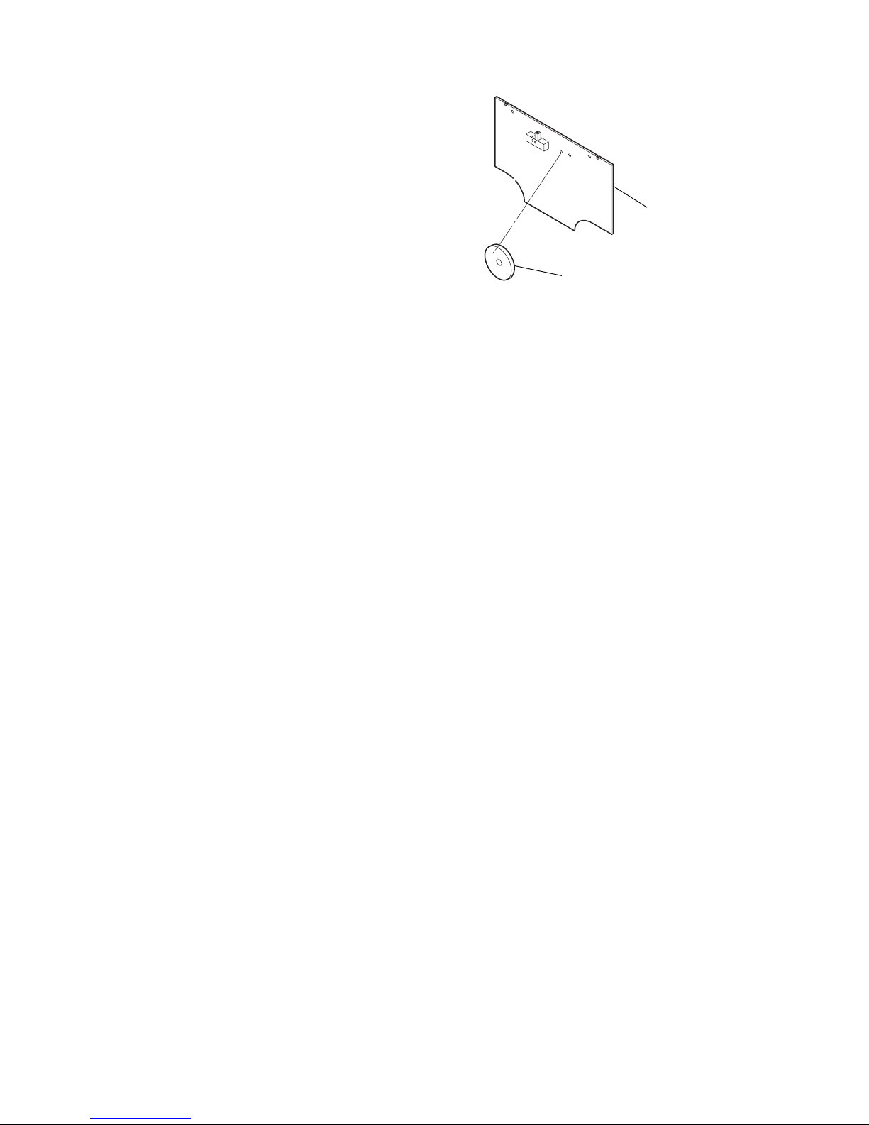
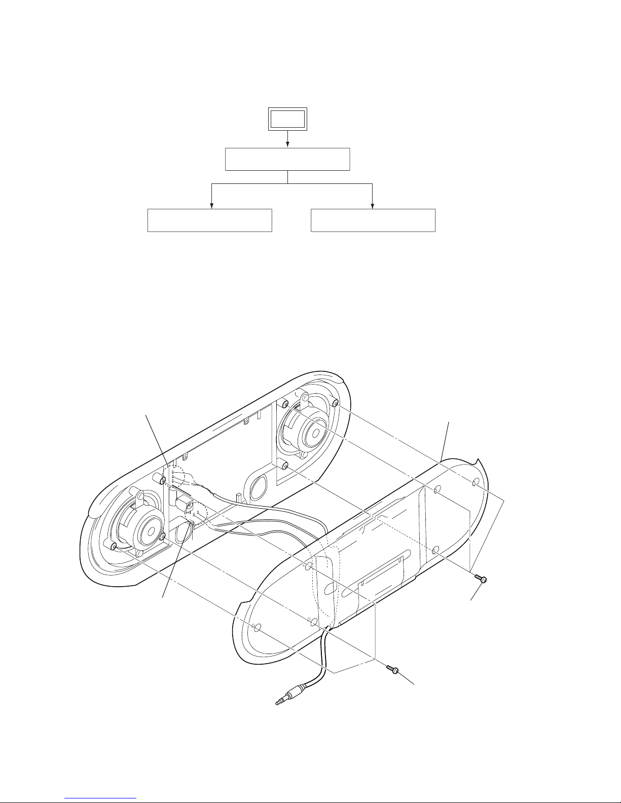
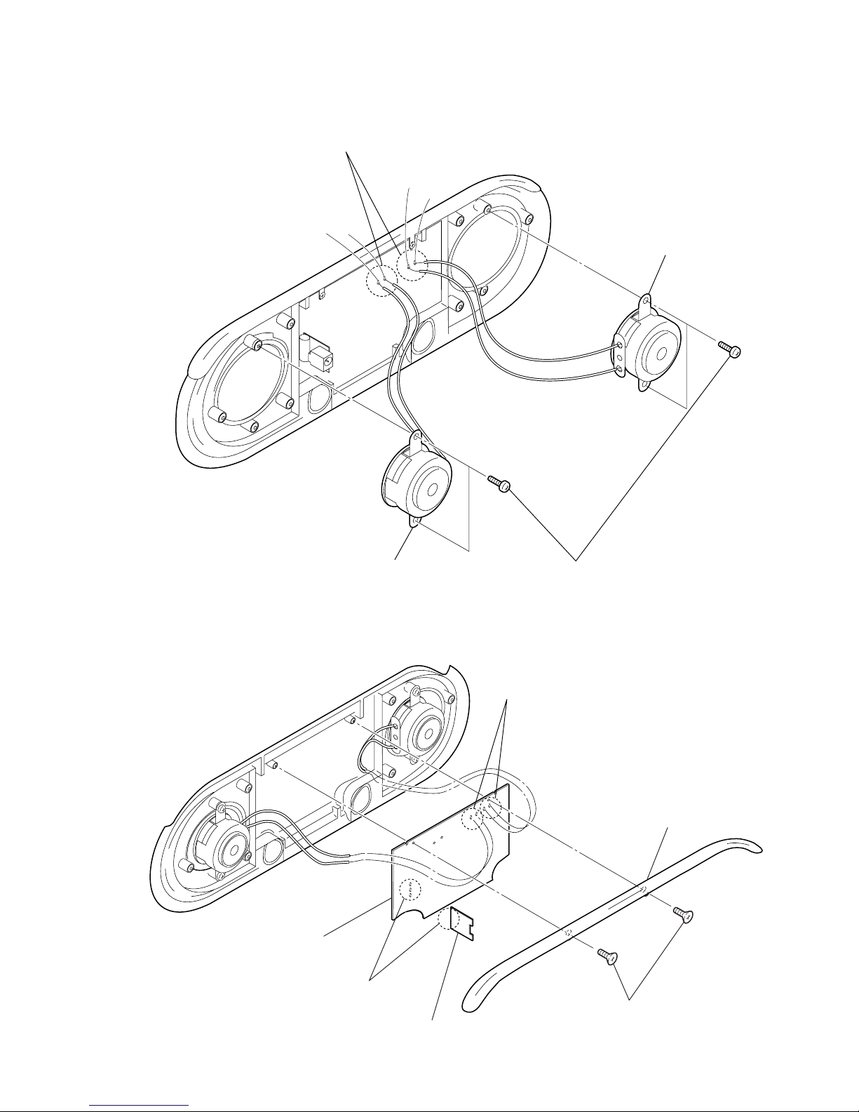
3. DISASSENBLY
3-1. REAR CABINET ··························································· 6
3-2. SPEAKER······································································· 7
3-3. AMP BOARD ································································· 7
4. DIAGRAMS
4-1. PRINTED WIRING BOARD ········································· 9
4-2. SCHEMATIC DIAGRAMS·········································· 10
5. EXPLODEDVIEWS ······················································ 12
6. ELECTRICAL PARTS LIST ······································· 13
Note on the AC power adaptor
Use only the supplied AC power adaptor. Do not use
any other AC power adaptor to avoid damaging the
speakers.
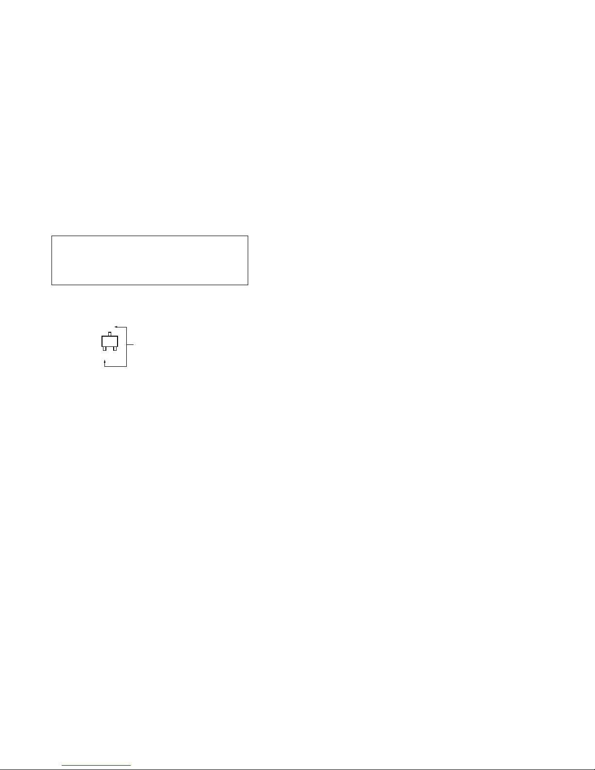
Polarity of the plug
On safety
The nameplate indicating operating voltage, power
consumption, etc., is located on the rear exterior.
• Before operating the system, be sure that the
operating voltage of the system is identical with that
of your local power supply.
Where purchased Operating voltage
U.S.A./Canada 120 V AC, 60 Hz
Other countries • 110 – 120 V AC, 50/60 Hz
• 220 – 230 V AC, 50 Hz
• Use only the supplied AC power adaptor.
• After operating the system with the AC power
adaptor, disconnect the AC power adaptor from the
wall outlet if the system is not to be used for an
extended period of time. The POWER switch does
not turn the AC power adaptor off.
SAFETY-RELATED COMPONENT WARNING!!
COMPONENTS IDENTIFIED BY MARK 0OR DOTTED LINEWITH
MARK 0ON THE SCHEMATIC DIAGRAMS AND INTHE PARTS
LIST ARE CRITICAL TO SAFE OPERATION. REPLACE THESE
COMPONENTS WITH SONY PARTS WHOSE PART NUMBERS
APPEAR AS SHOWN IN THIS MANUAL OR IN SUPPLEMENTS
PUBLISHED BY SONY.
ATTENTION AU COMPOSANT AYANT RAPPORT
À LA SÉCURITÉ!
LES COMPOSANTS IDENTIFÉS PAR UNE MARQUE 0SUR LES
DIAGRAMMES SCHÉMATIQUES ET LA LISTE DES PIÈCES SONT
CRITIQUES POUR LA SÉCURITÉ DE FONCTIONNEMENT. NE
REMPLACER CES COMPOSANTS QUE PAR DES PIÈSES SONY
DONT LES NUMÉROS SONT DONNÉS DANS CE MANUEL OU
DANS LES SUPPÉMENTS PUBLIÉS PAR SONY.

3
SRS-T88
SECTION 1
SERVICING NOTES
If the TV picture or monitor display is
magnetically distorted
Although this system is magnetically shielded, there
may be cases that the picture on some TV sets/personal
computer sets may become magnetically distorted. In
such a case, turn off the power of the TV set/personal
computer set once, and after 15 to 30 minutes turn it on
again. For the personal computer set, take the
appropriate measures such as data storage before
turning it off.
When there seems to be no improvement, locate the
system further away from the TV set/personal
computer set. Furthermore, be sure not to place objects
in which magnets are attached or used near the TV set/
personal computer set, such as audio racks, TV stands,
toys etc. These may cause magnetic distortion to the
picture due to their interaction with the system.
SUB ASSY, KNOB (VOLUME
)
(Part No.
:
X-3384-656-1)
AMP board
*RV1 (on AMP board)
Supply with a single article has not been carried out.
Please exchange by SUBASSY, KNOB (VOLUME).
(Part No. X-3384-656-1)

4
SRS-T88 SECTION 2
GENERAL
Using on house current
to DC IN 6 V jack
Vers la prise DC IN 6 V
a la toma DC IN 6 V
AC power adaptor
(supplied)
Adaptateur secteur
(fourni)
Adaptador de
alimentación de ca
(suministrado)
to wall outlet
Vers la prise
murale
Tomacorriente
OPEN
1
(rear)
(arrière)
(parte posterior)
2
Four R6 (size AA) batteries
Quatre piles R6 (format AA)
Cuatro pilas R6 (tamaño AA)
POWER VOLUME
MIN MAX
DIRECT
OFF ON
VOLUME
POWER
Battery installation
Listening to the sound
This section is extracted from
instruction manual.

5
SRS-T88
Hooking up the speakers
OPEN
OPEN
POWER VOLUME
MIN MAX
DIRECT
OFF ON
2
v
CD/MD Walkman*,
PC, etc.
Walkman* CD et MD,
Ordinateur ou un
autre appareil
Walkman de CD/
MD*, PC, etc.
* “WALKMAN” is a registered trademark of Sony
Corporation to represent Headphone Stereo
products.
« WALKMAN » est une marque déposée par
Sony Corporation pour représenter les produits
stéréo dotés d’écouteurs.
“WALKMAN” es una marca registrada de Sony
Corporation que representa los productos
audífonos estéreo.
POWER
1
3
To LINE OUT or to headphones
jack (stereo mini jack)
Vers LINE OUT ou vers la prise
de casque (mini-prise stéréo)
a la toma LINE OUT o a la toma
de auriculares (minitoma
estéreo)

6
SRS-T88 SECTION 3
DISASSENBLY
Note: Disassenbly the unit in the order as shown below.
SET
REAR CABINET
SPEAKER AMP BOARD
Note: Follow the disassembly procedure in the numerical order given.
3-1. REAR CABINET
1
three screws
(+P B2.6)
3
Remove two solders
of the AMP board.
4
Remove three solders of the AMP board.
2
three screws
(+P B2.6)
5
rear cabinet

7
SRS-T88
3-2. SPEAKER
(red)
(red)
(white)
(white)
1
Remove the
four solders.
2
four screws (+P B2.6)
4
speaker (SP1)
3
speaker (SP2)
3-3. AMP BOARD
1
two screws
(+P 2x6)
2
top cover
5
JACK board
6
AMP board
4
Reomve three solders
of the AMP board.
3
Remove four solders
of the AMP board.

8
SRS-T88 SECTION 4
DIAGRAMS
Note on Schematic Diagrams:
•All capacitors are in µF unless otherwise noted. pF: µµF
50 WV or less are not indicated except for electrolytics
and tantalums.
•All resistors are in Ωand 1/4W or less unless otherwise
specified.
•C: panel designation.
•A: B+ Line.
•Power voltage is dc 6V and fed with regulated dc power
supply from DC IN jack (J1).
•VoltagesaretakenwithaVOM(Inputimpedance 10 MΩ).
Voltage variations may be noted due to normal produc-
tion tolerances.
•Signal path.
F: AUDIO
Note on PrintedWiring Boards:
•Y: parts extracted from the conductor side.
•b: Pattern from the side which enables seeing.
Q
C
EB These are omitte
d
Caution:
Pattern face side: Partsonthepatternface side seen from
(SIDE A) the pattern face are indicated.
Parts face side: Parts on the parts face side seen from
(SIDE B) the parts face are indicated.
•Indication of transistor.

99
SRS-T88
4-1. PRINTED WIRING BOARD
SP2
(R CH)
SP1
(L CH)
ON OFF
10
1
20
11
10
1
20
11
POWER
VOLUME
DRY BATTERY
SIZE "AA"
(IEC DESGNATION LR6)
4PCS, 6.0V
12
(12)
12
(12)
12
(12)
12
(12)
12
(12)
C105
C106
IC1
IC2
12
A
B
C
D
34
DC
IN
STEREO
PLUG
(
(
(
(
E
E
Ref. No. Location
D1 C-4
D2 C-1
IC1 D-4
IC2 D-3
Q1 C-3
Q2 C-2
• Semiconductor
Location

1010
SRS-T88
4-2. SCHEMATIC DIAGRAMS
RV1(1/2)
RV1(2/2)
SW1(1/4)
SW1(2/4)
SW1(3/4)
SW1(4/4)
C9
C7
C10 C14
C12
C6
C11
R1
R2
C8
C16
C18
C19
C20
TP12
TP10
TP11
R3
C2
R4
R5
R6
R9
R10
R12
R13
R14
R15
R16
R17
C17
C15
TP15
TP16
TP17
J1
TP4
TP5
TP6
TP7
TP8
TP9
C23
C25
R8
R22
R7
R21
R11
C13
C24
C101
C1
IC1
Q1
C102
Q2
C104
IC2
D1
D2
C3
TP1
TP2
TP3
C22
C21
C4
C103
C5
10K
10K
16V
16V
16V 16V
4V
4V
4V
4.7k
4.7k
16V
6.3V
6.3V
16V
16V
GND
VCC+
JACK SW(GND)
220
220
1k
1k
220
220
2.2
1k
1k
1k
10k
10k
6.3V
6.3V
VCC
JACK SW(GND)
GND
L+
L-
R+
R-
B+
B-
10V
4.7k
4.7k
4.7k
4.7k
2.2
16V
TEA2025D-013TR
DTC144TKA-T146
DTC144TKA-T146
TEA2025D-013TR
1SS123-T1
UDZSTE-176.8B
50V
4V
16V
50V
4V
0.047
C106
C105

11
SRS-T88
• IC Block Diagram
IC1, IC2 TEA2025D-013TR (AMP board)
+
–
+
–
VCC
OUT 1
BOOT 1
GND
START
CIRCUIT
(THERMAL
PROTECT)
GND
GND
GND
GND
BOOT 2
OUT 2
BRIDGE
GND
GND
GND
SVR
FEEDBACKFEEDBACK
IN 1(+)IN 2(+)
GND(Sub)
20
19
18
17
16
15
14
13
12
11
1
1
1
2
2
2
3
4
5
6
7
8
9
10
DECOUPLING

SECTION 5
EXPLODEDVIEWS
NOTE:
•-XX, -X mean standardized parts, so they may
have some differences from the original one.
•Items marked “*” are not stocked since they
are seldom required for routine service. Some
delayshouldbe anticipated whenordering these
items.
•Themechanicalparts with no referencenumber
in the exploded views are not supplied.
12
SRS-T88
Ref. No. Part No. Description Remarks Ref. No. Part No. Description Remarks
17
18 23
22
22
SP1
1
2
11 12
13
15
21
14
10
11 9
20
19
23
16
16
4
5
7
5
6
21
16
16
21
4
3
8
a
a
16
16
SP2
1X-3384-186-1 CABINET ASSY, FRONT
2X-3384-656-1 SUB ASSY, KNOB (VOLUME)
33-258-788-01 KNOB (POWER)
43-258-790-11 PIPE
53-259-725-01 JOINT
63-260-136-02 URETHANE, JOINT
73-258-790-01 PIPE
83-258-783-01 COVER, TOP
93-258-784-01 LID, BATTERY CASE
10 3-258-785-01 STAND
11 3-260-137-01 URETHANE, BATTERY
12 3-258-792-01 SPRING, PLUS BATTERY
13 3-046-629-01 SPRING (B), BATTERY RELAY
14 3-258-791-01 SPRING, MINUS BATTERY
15 1-827-763-21 CORD (WITH PLUG)
16 3-260-134-01 SHEET, PACKING
17 3-258-786-01 PLATE, BATTERY
*18 A-4541-780-A AMP BOARD, COMPLETE
19 3-258-782-01 CABINET, REAR
20 3-046-628-01 SPRING (A), BATTERY RELAY
21 3-253-143-01 SCREW (B2.6), (+) P TAPPING
22 3-254-070-01 SCREW
23 3-260-135-02 URETHANE, PACKING
SP1 1-825-612-11 SPEAKER
SP2 1-825-612-11 SPEAKER

13
SRS-T88
NOTE:
•Due to standardization, replacements in the
parts list may be different from the parts
specifiedin the diagramsorthe components
used on the set.
•-XX, -X mean standardized parts, so they
may have some difference from the original
one.
•Items marked “*” are not stocked since they
are seldom required for routine service.
Some delay should be anticipated when
ordering these items.
•RESISTORS
All resistors are in ohms.
METAL: metal-film resistor
METAL OXIDE:Metal Oxide-film resistor
F: nonflammable
•CAPACITORS:
uF: µF
•COILS
uH: µH
•SEMICONDUCTORS
In each case, u: µ, for example:
uA...: µA... , uPA... , µPA... ,
uPB... , µPB... , uPC... , µPC... ,
uPD..., µPD...
•Abbreviation
CND : Canadian model
JE : Tourist model
•Accessories are given in the last of this parts
list.
When indicating parts by reference number,
please include the board name.
SECTION 6
ELECTRICAL PARTS LIST
The components identified by mark 0or
dotted line with mark 0are critical for safety.
Replace only with part number specified.
Les composants identifiés par une marque
0sont critiques pour la sécurité.
Ne les remplacer que par une pièce portant
le numéro spécifié.
AMP
*A-4541-780-A AMP BOARD, COMPLETE
********************
3-265-148-01 SHEET (L), INSULATING
3-265-149-01 SHEET (S), INSULATING
< CAPACITOR >
C1 1-165-176-11 CERAMIC CHIP 0.047uF 10.00% 16V
C2 1-165-176-11 CERAMIC CHIP 0.047uF 10.00% 16V
C3 1-126-193-11 ELECT 1uF 20% 50V
C4 1-126-193-11 ELECT 1uF 20% 50V
C5 1-126-209-11 ELECT CHIP 100uF 20.00% 4V
C6 1-126-209-11 ELECT CHIP 100uF 20.00% 4V
C7 1-117-681-11 ELECT CHIP 100uF 20.00% 16V
C8 1-117-681-11 ELECT CHIP 100uF 20.00% 16V
C9 1-117-681-11 ELECT CHIP 100uF 20.00% 16V
C10 1-117-681-11 ELECT CHIP 100uF 20.00% 16V
C11 1-126-209-11 ELECT CHIP 100uF 20.00% 4V
C12 1-126-209-11 ELECT CHIP 100uF 20.00% 4V
C13 1-117-681-11 ELECT CHIP 100uF 20.00% 16V
C14 1-117-681-11 ELECT CHIP 100uF 20.00% 16V
C15 1-125-837-91 CERAMIC CHIP 1uF 10% 6.3V
C16 1-125-837-91 CERAMIC CHIP 1uF 10% 6.3V
C17 1-125-837-91 CERAMIC CHIP 1uF 10% 6.3V
C18 1-125-837-91 CERAMIC CHIP 1uF 10% 6.3V
C19 1-107-826-11 CERAMIC CHIP 0.1uF 10.00% 16V
C20 1-107-826-11 CERAMIC CHIP 0.1uF 10.00% 16V
C21 1-124-779-00 ELECT CHIP 10uF 20% 16V
C22 1-126-208-21 ELECT CHIP 47uF 20.00% 4V
C23 1-126-925-91 ELECT 470uF 20.00% 10V
C24 1-125-891-11 CERAMIC CHIP 0.47uF 10.00% 10V
C25 1-125-891-11 CERAMIC CHIP 0.47uF 10.00% 10V
C101 1-162-964-11 CERAMIC CHIP 0.001uF 10% 50V
C102 1-162-964-11 CERAMIC CHIP 0.001uF 10% 50V
C103 1-162-964-11 CERAMIC CHIP 0.001uF 10% 50V
C104 1-162-964-11 CERAMIC CHIP 0.001uF 10% 50V
C105 1-162-964-11 CERAMIC CHIP 0.001uF 10% 50V
< DIODE >
D1 8-719-800-76 DIODE 1SS123-T1
< IC >
IC1 8-759-524-84 IC TEA2025D-013TR
IC2 8-759-524-84 IC TEA2025D-013TR
< TRANSISTOR >
Q1 8-729-027-60 TRANSISTOR DTC144TKA-T146
Q2 8-729-027-60 TRANSISTOR DTC144TKA-T146
< RESISTOR >
R1 1-216-829-11 METAL CHIP 4.7K 5% 1/16W
R2 1-216-829-11 METAL CHIP 4.7K 5% 1/16W
R3 1-216-813-11 METAL CHIP 220 5% 1/16W
R4 1-216-813-11 METAL CHIP 220 5% 1/16W
R5 1-216-821-11 METAL CHIP 1K 5% 1/16W
R6 1-216-821-11 METAL CHIP 1K 5% 1/16W
R7 1-216-829-11 METAL CHIP 4.7K 5% 1/16W
R8 1-216-829-11 METAL CHIP 4.7K 5% 1/16W
R9 1-216-813-11 METAL CHIP 220 5% 1/16W
R10 1-216-813-11 METAL CHIP 220 5% 1/16W
R11 1-216-789-11 METAL CHIP 2.2 5% 1/16W
R12 1-216-789-11 METAL CHIP 2.2 5% 1/16W
R13 1-216-821-11 METAL CHIP 1K 5% 1/16W
R14 1-216-821-11 METAL CHIP 1K 5% 1/16W
R15 1-216-821-11 METAL CHIP 1K 5% 1/16W
R16 1-216-833-11 METAL CHIP 10K 5% 1/16W
R17 1-216-833-11 METAL CHIP 10K 5% 1/16W
R21 1-216-829-11 METAL CHIP 4.7K 5% 1/16W
R22 1-216-829-11 METAL CHIP 4.7K 5% 1/16W
< SWITCH >
SW1 1-554-295-21 SWITCH, SLIDE (POWER)
************************************************************
JACK BOARD
**********
< CAPACITOR >
C106 1-162-964-11 CERAMIC CHIP 0.001uF 10% 50V
< DIODE >
D2 8-719-978-33 DIODE UDZSTE-176.8B
< JACK >
J1 1-568-907-21 ACK,DC(POLARITY UNIFIED TYPE)(DC IN)
************************************************************
Ref. No. Part No. Description Remarks Ref. No. Part No. Description Remarks
JACK
*RV1 (on AMP board)
Supply with a single article has not been carried out.
Please exchange by SUB ASSY, KNOB (VOLUME).
(Part No. X-3384-656-1)

Ref. No. Part No. Description Remarks
14
SRS-T88
MISCELLANEOUS
**************
15 1-827-763-21 CORD (WITH PLUG)
SP1 1-825-612-11 SPEAKER
SP2 1-825-612-11 SPEAKER
ACCESSORIES
************
01-476-219-13 ADAPTOR, AC (AC-E60A) (JE)
01-476-657-12 ADAPTOR, AC (CND, US)
01-569-007-12 ADAPTOR, CONVERSION 2P (JE)
3-258-804-01 MANUAL, INSTRUCTION (JAPANESE) (JE)
3-258-804-11 MANUAL, INSTRUCTION
(ENGLISH,FRENCH,SPANISH)
3-260-321-01 PORCH, CARRYING
The components identified by
mark 0or dotted line with mark
0are critical for safety.
Replace only with part number
specified.
Les composants identifiés par
une marque 0sont critiques
pour la sécurité.
Ne les remplacer que par une
pièceportantlenumérospécifié.

15
SRS-T88
MEMO

SRS-T88
REVISION HISTORY
Clicking the version allows you to jump to the revised page.
Also, clicking the version at the upper right on the revised page allows you to jump to the next revised
page.
Ver. Date Description of Revision
1.0 2004.01 New
Other manuals for SRS-T88 - Speaker - 4 Watt
1
Table of contents
Other Sony Speakers System manuals

Sony
Sony SA-VE335 User manual

Sony
Sony PMC-202 User manual

Sony
Sony SS-G5D Setup guide

Sony
Sony SA-VE835ED Installation instructions manual

Sony
Sony SRS-GU10iP Marketing User manual

Sony
Sony SS-SR5 Instruction Manual

Sony
Sony HT-ST9 User manual

Sony
Sony SRS SRS-AX10 User manual

Sony
Sony HT-CT350 Installation and operation manual

Sony
Sony Operating Instructions SRS-D200 User manual