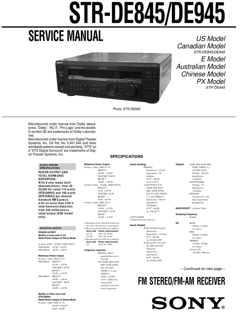
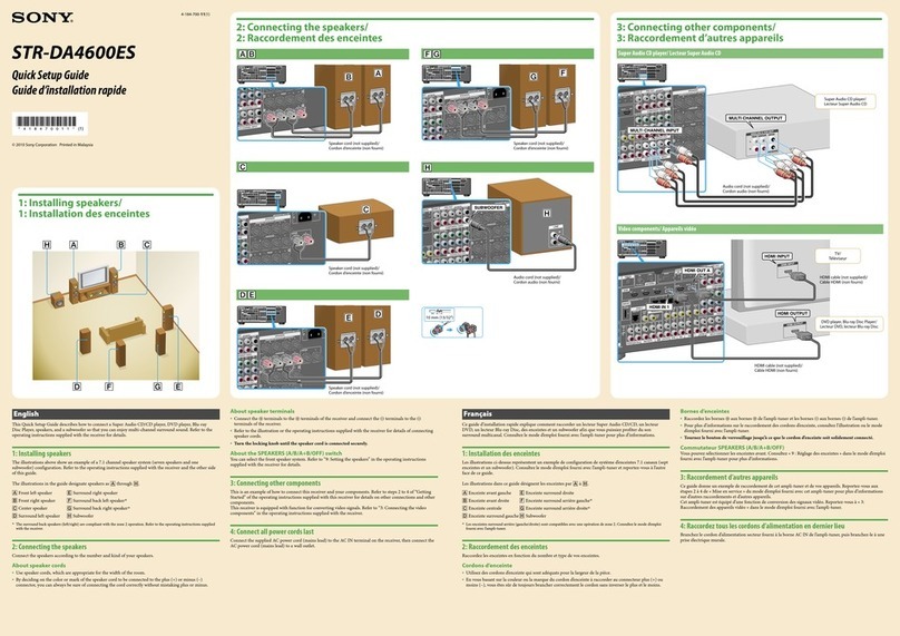
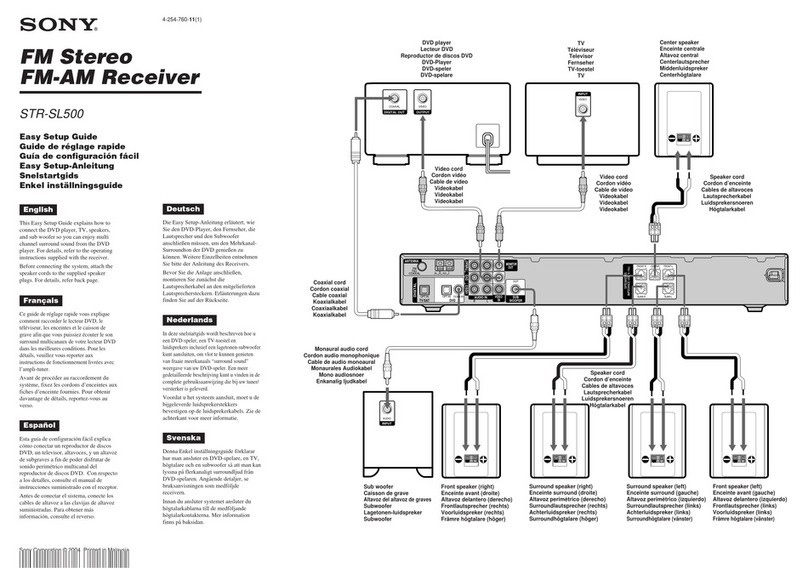
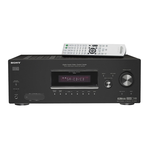
Sony STR-GX909ES User manual

SONY.
FM
Stereo/FM-AM
Receiver
Operating
Instructions
.
STR-GX909ES
STR-GX808ES

Warning
|
WARNING
To
prevent
fire
or
shock
hazard,
do
not
expose
the
unit
to
rain
or
moisture.
CAUTION
AN
A
DO
NOT
OPEN
CAUTION:
TO
REDUCE
THE
RISK
OF
ELECTRIC
SHOCK,
O00
NOT
REMOVE
COVER
(OR
BACK).
NO
USER-SERVICEABLE
PARTS
INSIDE.
REFER
SERVICING
TO
QUALIFIED
SERVICE
PERSONNEL.
This
symbol
is
intended
to
alert
the
user
to
the
presence
of
uninsulated
“dangerous
voltage"
within
the
product's
enclosure
that
may
be
of
sufficient
magnitude
to
constitute
a
tisk
of
electric
shock
to
persons.
This
symbol
is
intended
to
alert
the
user
to
the
presence
of
important
operating
and
maintenance
(servicing)
instructions
in
the
literature
accompanying
the
appliance.
Owner's
Record
The
model
number
is
located
on
the
rear
exterior
and
serial
number
is
on
the
rear.
Record
the
serial
number
in
the
space
provided
below.
Refer
to
these
numbers
whenever
you
call
upon
your
Sony
dealer
regarding
this
product.
Model
No.
Serial
No.
Note
to
CATV
system
installer
This
reminder
is
provided
to
call
the
CATV
system
installer's
attention
to
Article
820-40
of
the
NEC
that
provides
guidelines
for
proper
grounding
and,
in
particular,
specifies
that
the
cable
ground
shall
be
connected
to
the
grounding
system
of
the
building,
as
close
to
the
point
of
cable
entry
as
practical.
INFORMATION
This
equipment
has
been
tested
and
found
to
comply
with
the
limits
for
a
Class
B
digital
device,
pursuant
to
Part
15
of
the
FCC
Rules.
These
limits
are
designed
to
provide
reasonable
protection
against
harmful
interference
Ina
residential
installation.
This
equipment
generates,
uses,
and
can
radiate
radio
frequency
energy
and,
if
not
installed
and
used
in
accordance
with
the
instructions,
may
cause
harmful
interference
to
radio
communications.
However,
there
is
no
guarantee
that
interference
will
not
occur
ina
particular
installation.
If
this
equipment
does
cause
harmful
interference
to
radio
or
television
reception,
which
can
be
determined
by
turning
the
equipment
off
and
on,
the
user
is
encouraged
to
try
to
correct
the
interference
by
one
or
more
of
the
following
measures:
—
Reorient
or
relocate
the
receiving
antenna.
—
Increase
the
separation
between
the
equipment
and
receiver.
—
Connect
the
equipment
into
an
outlet
on
a
circuit
different
from
that
to
which
the
receiver
is
connected.
—
Consult
the
dealer
or
an
experienced
radio/TV
technician
for
help.
CAUTION
You
are
cautioned
that
any
changes
or
modifications
not
expressly
approved
in
this
manual
could
void
your
authority
to
operate
this
equipment.
For
the
customers
in
Canada
CAUTION
:
TO
PREVENT
ELECTRIC
SHOCK,
DO
NOT
USE
THIS
POLARIZED
AC
PLUG
WITH
AN
EXTENSION
CORD,
RECEPTACLE
OR
OTHER
OUTLET UNLESS
THE
BLADES
CAN
BE
FULLY
INSERTED
TO
PREVENT
BLADE
EXPOSURE.
This
apparatus
complies
with
the
Class
B
limits
for
radio
noise
emissions
set
out
in
Radio
Interference
Regulations.
CAUTION
Use
of
this
appliance
with
some
systems
may
present
a
shock
or
fire
hazard.
Do
not
use
with
any
units
which
have
the
following
marking
located
near
output,
WARNING:
HAZARDOUS
ENERGY
!.

BE-\e)(>meo)
mOrelali-alts
Introduction
OVOMVIOW:
sisicsccsccccssctecesdescecereuecdionesseuss
sesedessssovesecadsonesvebscsses
4
PrOCAUILIONS
isis
ccscccoessnedcccrecesccceseseseudesentdessseseesaucdedesssseasestes
5
Chapter
1
Getting
Started
UNPACKING
sssssscscssessctscesieceseocsedesceasessessonsonsdeonesnse
sodcvoasoesseoes
5
Checking
the
supplied
accessories
............ececseeeeers
5
Inserting
the
batteries
into
the
remote
commander
.....
5
Selecting
the
AM
tuning
interval
...........sscresereseeerees
5
Hooking
Up
the
SYStOM
0...
see
ssetsetectcnensssseescessereerens
6
Connecting
an
FM
antenna...
cseecseseseessesseseeeeees
6
Connecting
an
AM
antenna
...........ccesscssnerssseceereens
6
Connecting
audio
QUIPMENL.............esessetscrseseseeseee
7
Connecting
video
EQuIPMENE
.............cecserscssessescerenes
8
Connecting
speaker
SySteMs
............sscsssecssesecsesseessees
9
Connecting
the
external
power
amplifiers
AN,
a
Pre-AMplifier
se
csesrsssesessrecscseeseenseseeeees
10
Connecting
to
the
power
Outlet
...........ccsecssctsettsessens
11
Selecting
the
mode
of
the
FUNCTION/
SOUND
FIELD/PRESET
TUNING
buttons..................
11
Identifying
the
parts
ANd
CONTOIS
......
ec
sseeereneeeseeeees
12
FLOM
DANS]
ccesesessesevsenccesscevsvesssuptecosedescsbocsacessecusvessesses
12
REMOLE
COMMANCET
...........sccsserseccererssessrseesorserseeseeoes
14
Chapter
2
Basic
Operations
Operating
with
the
remote
COMMANAET
...........sceseereeseees
15
Changing
the
settings
of
the
FUNCTION
buttons
........
15
The
on-screen-display
(STR-GX909ES
only)
...........ss0e0.
16
Adjusting
basic
audio
Controls
.........cscssssssssesesssersseereees
Adjusting
VOIUME
.........s.cscesesessceescsesseseneees
aseseysbaavessnees
Adjusting
left
and
right
sound
balance
Reinforcing
the
Dass
..........eeccssscseeseerteeeeeees
ase
Selecting
the
speaker
SYSteM
.........scccssseeeeeesesreeees
Selecting
&
Prograrn
SOUPCE
........csrsscsersersscessecesrsesesees
To
turn
off
the
power
at
the
desired
time
(The
sleep
tIMEF
FUNCTION)
.........ssecscrerscsscsesscsrserscsstseesesessseserensees
17
Labeling
the
program
SOUICE
.........sssrsssessercrenscseeees
18
Receiving
broadcasts
.........ceserecscsssescessersesseesoserorees
19
Tuning
in
a
station
directly
(Direct
tuning)
..............006
19
Automattic
tuning
............ceeecrsesserscesessesesscesceceseeees
20
Presetting
stations
(Station
preset)
............sccrseeeeee
21
Tuning
in
a
preset
station
(Preset
tuning)
..............000+
22
Labeling
the
preset
stations
(Station
index)................
23
Selecting
a
station
among
the
preset
stations
in
the
INAEX
(INDEX
TUNING)
.......ececcecceseceesereeseatseceesseseeesees
24
Receiving
FM
simulcast
TV
programs
..............seecee
24
Selecting
a
factory-preset
SOUNC
EFFECTS
...........cecrreercers
25
Recording
ann
AudiO
SOUFCE
........
cc
csesccrrenreccescnescreeseeeess
26
Recording
onto
an
audio
tape
deck
or
DAT
deck
......
26
TANG
GUDDING
iv
ccivceccsssccss
esse
ceocenseseoasecncucsncsseseaasseesess
26
Editing
&
VIGO
SOUICE
0.0...
ee
cccteceseetescsetscscerenrensseronee
27
Video
tape
GUDDING
............cccsscesseeccessessceereesensesseees
27
Adding
new
sound
on
a
video
tape
during
video
OGIING
coesce
sites
ecchscscctesacescassistcoucetesnressenssoseteebesbriscsnste
28
Chapter
3
Advanced
Operations
What
is
the
digital
signal
processor
?
...........sssesssseesssneneees
SOuN
field
SEUNG
...........ecccrsessetseserssessssssestscersetsoeseeees
Table
of
adjustable
parameters
............csscsscerserssseoees
Getting
ready
for
Dolby
surround
SOUNG
............seeres
Placement
of
speakers
and
selecting
the
PRO
LOGIC
MODE
...........csccsccscsssnsssessessesesesescnssonees
Adjusting
the
speaker
VOIUME
...........csseresssecsscrenseees
Adjusting
the
delay
time
of
the
rear
speakers
.............
Adjusting
the
SOUND
FIELD
program..........scscesreseseseee
Understanding
the
digital
surround
processor
............
Characteristics
of
the
SOUND
FIELD
program............
Adjusting
the
surround
effect
............csscsssenesscrenees
Understanding
the
digital
parametric
equalizer
..........
How
to
adjust
the
digital
parametric
equalizer
............
Enjoying
with
your
private
Setting
...........sscsoscrsereneeseee
Calling
up
the
Sound
field
Setting
0.0...
essere
Linking
the
sound
field
memory
to
preset
stations
OF
PFOGTAM
SOUICES
.......cccessescrsecessscseseesaneessensossees
Chapter
4
Other
Operations
Superimposing
the
title
and
illustration
(STR-GXQOQES
OMMy)
.......seccscesssssrccnsecssseersessstsonsessnsaees
How
to
use
the
titler
FUNCTION
0.
ececeeeetetesesesesees
Storing
other
manufacturer's
operating
codes
onto
the
remote
Commander
RM-P331
...........scsessccereevesssseees
Programming
signals
of
other
audio/video
SCUPIMION
Gis
sdesisess
ics
cacerescncdeckdebesesasHetecatedicstesupessectes
Programming
a
new
signal
onto
a
previously
PFOQrFAMME
DULION
.........ccceersorsrscrrcrseeorseeeseensceeees
Controlling
CQuipMent
............cercsererresscsssctsereseneenee
Chapter
5
Other
Information
Troubleshooting
QUIDe
.............cseserscsesceressrsstseressseeenees
SP@CiFICATIONS
.........
se
ccsersesessecrsrescesesceseectseesecsesrenenneneeees
QUICK
FEFEFENCE
.......cceccerscscescssrssescrsessessseeseessrsnresensesereee
“#
Se
Fe,
Sea
Whee
,
‘
7
bed
Sener
ON
Uae
ME
The
STR-GX909ES/STR-GX808ES
is
an
FM
Stereo/FM-AM
receiver
and
audio/video
control
center.
You
can
enjoy
various
audio/video
program
sources
with
this
unit.
Amplifier
*
Optical
Legato
Linear
A
System
allows
the
receiver
to
operate
automatically
as
a
class
A
amplifier
when
the
level
is
low
and
as
a
class
B
amplifier
when
the
level
is
high
without
disturbing
the
sound
signal.
This
minimizes
total
harmonic
distortion
at
every
sound
stage.
¢
This
receiver
has
a
spontaneous
twin
drive
power
circuit.
Condensers
having
large
capacity
are
used
independently
for
the
voltage
amplification
drive
stage
of
class
A
and
power
output
stage
of
class
B.
Thus,
a
stable
output
and
high
quality
sound
are
obtained,
resulting
in
exclusion
of
power
interferences.
The
class
A
stage
realizes
a
stable
operation
free
from
interference
of
the
power
stage
even
when
an
instantaneous
or
strong
output
is
received.
TVivideo
programs
e
You
can
enjoy
TV
or
CATV
programs
with
FM
simulcast.
©
Sounds
from
various
audio
program
sources
can
be
added
on
video
tapes
during
editing.
Tuner
¢
Precise
tuning
is
ensured
by
a
quartz
locked
digital
synthesizer.
*
Station
Index
system
allows
you
to
tune
into
a
station
quickly.
Powerful
surround
sound
By
connecting
the
power
amplifier
to
the
SURROUND
OUT
jacks
of
this
unit,
you
can
obtain
powerful
surround
sound.
Dynamic
sound
from
the
front
speakers
By
connecting
the
power
amplifier
and
the
pre-amplifier
to
the
PRE
OUT
and
MAIN
IN
jacks
of
this
unit
respectively,
you
can
obtain
a
dynamic
sound
from
the
front
speaker.
(See
page
10)
LOW
FILTER
switch
This
unit
has
the
LOW
FILTER
switch
which
cut
the
low
frequency
signal
from
the
front
speakers.
(See
page
10)
Digital
surround
processor
*
The
STR-GX909ES/STR-GX808ES
electronically
reproduces
the
reflected
sound
(early
reflection)
and
reverberation
sound
(reverberation)
by
using
its
digital
signal
processor,
and
allows
you
to
obtain
the
acoustics
of
various
situations.
DOLBY*
PRO
LOGIC:
The
STR-GX909ES/STR-GX808ES
incorporates
the
Dolby
Pro
Logic
Surround
Decoder
which
has
the
same
functions
for
playback
as
movie
theaters
and
gives
a
theater-like
experience
in
your
a
room,
naturally
reproducing
the
audio
sound
ield.
.
Manufactured
under
license
from
Dolby
Laboratories
Licensing
Corporation.
Additionally
licensed
under
one
or
more
of
the
following
patents:
U.S.
number
3,959,590:
Canadian
numbers
1,004,603
and
1,037,877.
“Dolby”,
“Pro
Logic”,
and
the
double-D
symbol
are
trademarks
of
Dolby
Laboratories
Licensing
Corporation.
Digital
parametric
equalizer
You
can
enjoy
audio
program
sources
with
appropriate
equalization
curve
by
controlling
the
level
of
the
desired
3
frequency
bands.
Sound
field
¢
10
recommended
sound
field
programs
(combination
of
surround
and
parametric
equalizer
settings)
are
preset
in
the
factory
for
easy
use.
You
can
also
store
up
to
10
settings
you
created
in
the
memory.
©
Combined
use
of
the
sound
field
programs
and
the
preset
stations
allow
you
to
enjoy
broadcast
listening
immediately
with
the
memorized
sound
field
settings.
ON
SCREEN
function
(STR-GXS09ES
only)
This
function
allows
you
to
monitor
the
operation
being
performed
on
the
monitor
TV.
TITLE
function
(STR-GX909ES
only)
With
this
function,
you
can
edit
a
title
and
superimpose
on
your
picture.
Remote
commander
supplied
The
STR-GX909ES/STR-GX808ES
is
supplied
with
the
RM-P331
which
can
“tearn”
the
various
functions
of
other
remote
commanders
of
the
infrared
type.
The
FUNCTION/SOUND
FIELD/PRESET
TUNING
buttons
There
are
two
kinds
of
modes
for
the
FUNCTION/SOUND
FIELD/PRESET
TUNING
buttons.
One
is
the
“Auto
mode”
and
the
other
is
the
"Manual
mode".
With
these
modes,
you
can
conveniently
operate
this
receiver.
This
manual
describes
the
operations
in
the
auto
mode.
This
instruction
manual
covers
the
STR-GX909ES
and
STR-GX808ES.
The
followings
are
only
for
the
STR-GX909ES.
©
ON
SCREEN
function
©
TITLE
function
©
Side
panels
The
illustration
used
in
the
manual
are
mainly
the
STR-GX909ES.

Precautions
On
safety
©
Operate
the
unit
only
on
120
V
AC,
60
Hz.
¢
Should
any
solid
object
or
liquid
fall
into
the
cabinet,
unplug
the
unit
and
have
it
checked
by
qualified
personnel
before
operating
it
any
further.
©
Unplug
the
unit
from
the
wall
outlet
if
it
is
not
to
be
used
for
an
extended
period
of
time.
To
disconnect
the
cord,
pull
it
out
by
grasping
the
plug.
Never
pull
the
cord
itself.
©
One
blade
of
the
plug
is
wider
than
the
other
for
the
purpose
of
safety
and
will
fit
into
the
power
outlet
only
one
way.
If
you
are
unable
to
insert
the
plug
fully
into
the
outlet,
contact
your
dealer.
©
To
detach
the
side
panel,
first
disconnect
the
power
cord
from
the
wall
outlet.
Remove
the
screws
on
both
sides
to
detach
the
panels
and
fasten
the
supplied
screws
into
the
holes
on
the
unit.
(STR-GX909ES
only)
To
prevent
internal
heat
buildup
in
the
unit,
place
the
unit
in
a
location
with
adequate
air
circulation.
Do
not
install
the
unit:
©
near
heat
sources
such
as
radiators
or
air
ducts.
¢
in
a
place
subject
to
direct
sunlight,
excessive
dust,
mechanical
vibration
or
shock.
Do
not
place
anything
on
top
of
the
cabinet.
The
top
ventilation
holes
must
be
unobstructed
for
the
proper
operation
of
the
unit
and
to
prolong
the
life
of
its
components.
Do
not
throw
away
the
carton
and
packing
material!
It
will
be
an
ideal
container
when
transporting
the
system
for
repair
work,
etc.
On
operation
Before
making
program
source
connections,
be
sure
to
turn
the
power
switch
off
and
unplug
the
unit.
On
cleaning
the
cabinet
Clean
the
cabinet,
panel
and
controls
with
a
soft
cloth
lightly
moistened
with
mild
detergent
solution.
Do
not
use
any
type
of
abrasive
pad,
scouring
powder,
or
solvent
such
as
alcohol
or
benzine.
For
the
customers
in
the
U.S.A.
For
detailed
safety
precautions,
see
the
“IMPORTANT
SAFEGUARDS’
leaflet.
If
you
have
any
question
or
problem
concerning
your
unit,
please
consult
your
nearest
Sony
dealer.
Chapter
1
Getting
Started
Ua}
ey-lol
dare,
Checking
the
Supplied
Accessories
After
unpacking,
check
that
the
following
accessories
are
present.
©
FM
Wire
Antenna
...........sesescccescssceeseessccssecesseseessencesoes
(1)
©
AM
J00P
ANTENNA
......ceceessesesseseteetsesonscsessonsesereesecseseenes
(1)
¢
Remote
commander
RM-P331
..........csersscssecscssesersees
(1)
©
Sony
batteries
SUM-3
(NS)
0.0.0...
ccscserccectecereseeoees
+..(2)
©
Screws
(STR-GXQOQES
Oly)
uu...
sesscrscsessesseeeseesessones
(4)
Natcyela
clave
Mm
datom
stat
ecole
(ctomlatcom
(arc
ats]nirel
cs
Commander
Before
operating
remote
commander,
install
the
batteries
as
shown.
2
Two
size
AA
(R6)
batteries
with
correct
polarity.
1
Open
the
cover.
To
avoid
damage
caused
by
battery
leakage
and
corrosion
When
the
commander
will
not
be
used
for
a
long
time,
remove
the
batteries.
Battery
life
Normal
operation
can
be
expected
about
a
half
year
using
Sony
SUM-3
(NS),
and
a
year
using
Sony
AM-3
(NW)
alkaline
batteries.
When
the
batteries
are
run
down,
the
remote
commander
will
not
operate
the
unit.
In
this
case,
replace
batteries
with
new
ones.
Selecting
the
AM
Tuning
Interval
The
AM
tuning
interval
is
preset
to
10
kHz.
To
use
the
receiver
where
the
frequency
allocation
system
is
based
on
a
9
kHz
interval,
make
the
following
adjustments.
1
Turn
on
the
power
and
tune
in
any
AM
siation.
2
Turn
off
the
power.
3
Press
the
POWER
button
while
pressing
the
INDEX
SELECT/TUNING
+
button.
To
reset
the
AM
tuning
interval,
repeat
the
above
steps.
Caution
When
the
interval
is
changed,
all
preset
stations
which
you
have
memorized
will
be
erased.
After
changing
the
interval,
be
sure
to
preset
the
stations
again.
5

wene)
lth
Hooking
Up
the
System
At
first,
this
section
describes
about
the
antenna
connection
and
then
the
connection
with
the
other
equipment.
After
that,
it
shows
about
the
speaker
connection
and
about
the
AC
outlet.
The
STR-GXS809ES/STR-GX808ES
has
the
SURROUND
OUT
jacks
on
the
rear
panel.
©
Do
not
connect
the
power
cord
to
an
AC
outlet
nor
press
the
POWER
switch
before
accomplishing
all
other
connections.
©
The
cable
connectors
should
be
fully
inserted
into
the
jacks.
Loose
connection
may
cause
hum
and
noise.
*
Jacks
and
plugs
of
the
connecting
cord
are
color-coded
as
follows:
Red
jacks
and
plugs:
For
the
right
channel
of
audio
signals
White
jacks
and
plugs:
For
the
left
channel
of
audio
signals
Yellow
jacks
and
plugs:
For
video
signals
Connecting
an
FM
Antenna
Though
the
wire
antenna
is
supplied
with
this
unit,
the
higher
quality
sound
will
be
obtained
with
the
75-ohm
coaxial
cable.
Supplied
wire
antenna
For
higher
quality
sound
75-ohm
coaxial
cable
(optional)
Ofoyalatzrostiale
m-taWANi
imal
(ralar:|
The
AM
broadcast
is
enough
received
with
the
supplied
AM
loop
antenna.
However,
the
connection
of
insulated
wire
is
also
available
for
areas
with
difficult
AM
reception.
Adjust
the
direction.
“
Ca
m
Supplied
AM
loop
antenna
For
areas
with
difficult
AM
reception
In
areas
with
troubled
reception,
connect
a
6
to
15-meter
(20
to
50-feet)
insulated
wire
to
the
AM
antenna
terminal.
Extend
this
out
of
doors
if
possible,
keeping
the
greater
portion
horizontal.
(There
is
no
need
to
disconnect
the
supplied
antenna.)
To
prevent
hum
Connect
the
ground
wire
to
ANTENNA
ground
terminal
(74).
When
an
outdoor
antenna
is
installed,
be
sure
to
connect
the
ground
wire
for
lightning
protection.

(Ofe}
ajatszea
(lalem-velel(om
corel)
elsetszane
Receiver
Other
equipment
White
White
LO
-OL
RO
=»©R
Red
Red
Pre-amplifier
for
|
{Power
amplifier
for
|
{Monaural
power
amplifier]
the
front
speakers
for
a
center
speaker
Subwoofer,
etc.
Power
amplifier
for
the
front
speakers
CD
player
;
to
LINE
OUT
T.
tack
2
:
‘ape
dec
to
OUTPUT
to
LINE
IN
to
LINE
IN
to
LINE
OUT
:
to
LINE
IN
to
LINE
OUT

OXolelatzioudjarepdlel-rom
=toret|olar(=ia)'
Vv
IN
RYIPEO
Monitor
TV
1
to
VIDEO
3/
INPUT
on
the
front
panel
to
AUDIONVIDEO
OUT
to
AUDIO/VIDEO
IN
to
AUDIO/VIDEO
OUT
VCR
3
Camera/
to
AUDIO
IDEO
OUT
Caution
(STR-GX909ES
only)
When
the
MONITOR
VIDEO
OUT
jack
is
connected
and
ON
SCREEN
ON/OFF
is
set
to
ON,
the
cursor
mode
operation
buttons
cannot
be
used
for
the
other
functions
than
the
ON
SCREEN
function.

Connecting
Speaker
Systems
Front,
center
and
rear
speakers
can
be
connected
to
this
unit.
Front
Front
speaker
(R)
__
Speaker
(L)
Approx.15
mm
Approx.
15mm
(*/,,
inches)
=>
to
the
second
front
speaker
system
mme!MPEDANCE
SELECTOR
Rear
speaker
(L)
Rear
speaker
(R)
Center
speaker
On
the
IMPEDANCE
SELECTOR
Note
The
STR-GX909ES/STR-GX808ES
have
the
IMPEDANCE
When
connecting
the
speaker
cord
to
the
speaker
terminal,
SELECTOR
for
front
or
center
speaker(s).
¢
When
using
the
front
or
center
speaker(s)
having
nominal
impedance
from
4
ohms
or
higher,
set
to
the
4
Q
position.
¢
When
using
the
front
or
center
speaker(s)
having
nominal
impedance
from
8
ohms
or
higher,
set
to
the
8
Q
position.
¢
When
using
both
FRONT
SPEAKERS
A
and
B
systems,
use
the
speakers
having
the
nominal
impedance
of
more
than
8
ohms
and
set
the
IMPEDANCE
SELECTOR
to
the
4
Q
position.
make
sure
that
the
polarity
(+
and
—)
of
the
speaker
cord
is
correct.
If
the
polarity
is
reversed
at
either
speaker,
the
sound
will
be
distorted
and
will
lack
bass.

OFelale(crou
ciate
mcal-m
=>acciear-l
mou
slaw
Venlo)
ibi(s)ce-lale
Nem
mecercliileliitizig
By
connecting
the
external
power
amplifiers
and
a
pre-amplifier
to
this
receiver,
you
can
obtain
a
powerful
sound.
Power
amplifier
for
,
Power
amplifier
for
*
[Monaural
power
amplifier
the
front
speakers
the
rear
speakers
for
a
center
speaker
LOW
FILTER
switch
Pre-amplifier
for
the
front
speakers
Subwoofer
with
a
power
amplifier
Before
connecting
the
PRE
OUT/MAIN
IN
jacks,
remove
the
shorting
plugs.
When
the
PRE
OUT/
MAIN
JN
jacks
are
not
connected,
keep
the
shorting
plugs
inserted.
When
connecting
a
monaural
power
amplifier
for
a
center
speaker
Connect
the
input
jack
of
the
power
amplifier
to
the
SURROUND
CENTER
jack
of
this
receiver.
When
connecting
a
subwoofer
with
a
power
amplifier
Connect
the
line
input
jack
of
the
subwoofer
to
the
SURROUND
MONO
jack
of
this
receiver.
When
using
subwoofer
not
having
a
power
amplifier,
connect
through
a
monaural
power
amplifier.
When
connecting
a
power
amplifier
for
the
rear
speakers
Connect
the
input
jacks
of
the
power
amplifier
to
the
SURROUND
OUT
REAR
jacks
of
this
receiver.
10
When
connecting
a
pre-amplifier
for
the
front
speakers
Connect
the
input
jacks
of
the
pre-amplifier
to
the
MAIN
IN
jacks
of
this
receiver.
When
connecting
a
power
amplifier
for
the
front
speakers
Connect
the
input
jacks
of
the
power
amplifier
to
the
PRE
OUT
jacks
of
this
receiver.
To
obtain
a
powerful
sound
from
the
rear
speakers
Insert
the
shorting
plugs
to
the
MAIN
IN
and
SURROUND
OUT
REAR
jacks
and
then
connect
the
power
amplifier
to
the
PRE
OUT
jacks.
On
the
LOW
FILTER
ON/OFF
switch
With
setting
the
LOW
FILTER
to
ON,
the
low
frequency
signal
from
the
front
speakers
will
be
cut,
and
better
sound
effect
may
be
obtained
when
using
a
subwoofer.

Oe)
aa(ztoi
(tale
m
Comtalem
consi
-
am
Olea(=¥i
By
connecting
the
power
cord
of
the
other
audio
equipment
to
SWITCHED
AC
OUTLET,
this
unit
can
supply
the
power
source
to
the
other
audio
equipment.
Caution
Be
careful
that
the
total
power
consumption
of
each
equipment
connected
to
the
outlets
on
the
receiver
does
not
exceed
120
watts.
Do
not
connect
electrical
home
appliances
such
as
an
electric
iron,
fan,
TV,
or
other
high-wattage
equipment
to
these
outlets.
Selecting
the
Mode
of
the
FUNCTION/SOUND
FIELD/PRESET
TUNING
Buttons
There
are
two
kinds
of
modes
for
the
FUNCTION/SOUND
FIELD/PRESET
TUNING
buttons.
One
is
the
“Auto
mode"
and
the
other
is
the
“Manual
mode".
¢
Auto
mode
The
FUNCTION/SOUND
FIELD/PRESET
TUNING
buttons
are
factory
preset
to
the
auto
mode:
After
one
of
the
FUNCTION
buttons,
SOUND
FIELD
LINK,
SOUND
FIELD
ON/OFF
or
SOUND
FIELD
USER/PRESET
is
pressed,
the
FUNCTION/SOUND
FIELD/PRESET
TUNING
buttons
change
to
the
SOUND
FIELD
mode
automatically.
When
TUNER
is
pressed,
these
buttons
function
as
numeric
buttons.
¢
Manual
mode
When
you
press
the
POWER
switch
while
pressing
MODE
SELECT,
the
FUNCTION/SOUND
FIELD/PRESET
TUNING
buttons
are
set
to
the
manual
mode.
With
MODE
SELECT,
you
can
select
the
desired
mode.
To
return
to
the
auto
mode,
perform
the
same
procedure
again.

Identifyin
ng
th
the
Lela
dale
Co
meme
at
ee
ce
Front
Panel
These
illustrations
are
STR-GX909ES.
The
STR-GX808ES
is
not
equipped
with
the
ON
SCREEN
ON/OFF,
TITLE
ON/OFF
and
TITLE
IN/OUT
buttons.
Tee
TT
Ei
ee
|
|
|
|
fe
See
12

[1]
POWER
switch
[2]
ON
SCREEN
ON/OFF
button
(STR-GX909ES
only)
[3]
Remote
sensor
[4]
Display
[5]
Cursor
mode
indicators
(See
pages
18,
23, 32, 33,
35,
38.)
[6]
Cursor
mode
operation
buttons
(See
pages
18,
23,
32,
33,
35, 38,
40)
CURSOR
MODE/TITLE
MENU
button
(See
pages
18,
23, 32,
33, 35, 38,
40.)
DBFB
button
and
indicator
(See
page
16.)
.
[9]
MASTER
VOLUME
control
(See
page
16.)
SPEAKERS
selector
(See
page
16.)
[17]
HEADPHONES
jack
[12]
TITLE
ON/OFF
button
(See
pages
40,
41.)
(STR-GX909ES
only)
[13]
TITLE
IN/OUT
button
(See
page
41.)
(STR-GX909ES
only)
MUTING
button
and
indicator
(See
page
1
6.)
[15]
VIDEO
3/INPUT
jacks
BALANCE
control
(See
page
16.)
EDIT
VIDEO/AUDIO
buttons
(See
pages
27,
28.)
DISPLAY
GRAPHIC
button
(See
page
38.)
DISPLAY
INDEX
button
(See
pages
20,
24.)
INDEX
SELECT/TUNING
-/+
buttons
(See
pages
20,
24.)
[21]
PRESET
TUNING
-/+
buttons
(See
pages
22,
24.)
TUNING
LEVEL
button
(See
page
20.)
[23]
MEMORY
button
(See
pages
18,
21,
23.)
DIRECT
TUNING
button
(See
page
19.)
FM
MODE
button
(See
page
19.)
[26]
FM/AM
button
(See
pages
19,
20.)
27]
SOUND
FIELD
LINK
button
(See
page
39.)
SOUND
FIELD
ON/OFF
button
(See
pages
32,
33.)
SOUND
FIELD
USER/PRESET
button
(See
pages
35,
38,
39.)
ES
DOLBY
PRO
LOGIC
MODE
button
(See
pages
31,
32.)
EQUALIZER
FLAT
button
(See
page
38.)
[34
EQUALIZER
SLOPE
button
(See
page
38.)
EQUALIZER
BAND
button
(See
page
38.)
TAPE
2
MONITOR
button
and
indicator
(See
page
26.)
[35]
SHIFT
button
(See
pages
21,
22,
23.)
(36)
FUNCTION/SOUND
FIELD/PRESET
TUNING
buttons
(See
page
11.)
:
MODE
SELECT
button
(See
page
11.)

at=)aalolccm
Oxolanleatstarelsva
When
you
manipulate
a
switch
or
button
on
the
commander,
be
sure
to
point
the
head
of
the
commander
toward
the
remote
control
sensor
on
the
front
of
the
receiver.
If
there
is
an
obstacle
between
the
receiver
and
the
head
of
the
commander,
the
receiver
may
not
be
controlled
remotely.
RM-P331
(i)
Program
control
section
Mode
selector
and
indicator
SONY
STD:
To
control
Sony
equipment.
USER
STD:
To
control
equipment
whose
remote
control
functions
are
stored.
LEARN:
To
store
functions
of
other
remote
commanders
emitting
infrared
rays.
PROGRAM
CLEAR:
Clears
the
stored
functions.
[2]
Receiver
control
section
FUNCTION
(DAT,
CD,
TUNER,
PHONO,
VIDEO
1,
VIDEO
2,
VIDEO
3,
TAPE)
buttons:
The
each
function
is
selected
and
the
each
unit
enters
its
operating
mode
automatically.
SYSTEM
OFF:
Turns
off
the
power
of
the
whole
system.
SOUND
FIELD
buttons
USER/PRE
(user/preset):
Selects
the
USER
or
PRESET
mode.
MODE:
Selects
the
sound
field
mode.
ON/OFF:
Turns
on/off
the
sound
field
system.
14
BAND:
Selects
the
frequency
band
of
the
equalizer.
EQ:
Turns
on/off
the
setting
of
the
equalizer
and
TONE
controls.
T.
(test)
TONE:
Generates
a
pink
noise
signal
that
is
sent
in
succession
to
each
speaker.
CURSOR
MODE:
Select
CURSOR
MODE.
CURSOR
operating
buttons
REAR
LEVEL
+/-
buttons:
Control
the
volume
of
rear
speakers
(surround
level).
CENTER
LEVEL
+/—
buttons
:
Control
the
volume
of
center
speaker
(surround
level).
DBFB
button:
Turns
on/off
the
DBFB
(Dynamic
Bass
_Feedback).
MUTING
button:
Mutes
the
sound.
MASTER
VOL
+/-
buttons:
Control
the
receiver
volume.
SLEEP:
Set
to
the
SLEEP
timer
mode.
in
this
mode,
the
unit
is
automatically
turned
off
after
the
designated
time.
(This
button
functions
only
for
STR-GX909ES)
ON
SCREEN
ON/OFF
button:
Turn
on/off
the
ON
SCREEN
mode.
(This
button
functions
only
for
STR-
GX909ES)
Other
equipment
control
section
The
operative
buttons
are
changed
according
to
the
function
mode
and
the
setting
of
the
SYSTEM/TV
selector.
Numeric
buttons
(7
to
0):
Designate
the
number.
>10:
Designates
the
number
more
than
10.
ENTER:
Press
after
designating
the
TV/VCR
channel.
SHIFT:
Select
the
memory
page
(A,
B
or
C)
only
in
the
TUNER
mode.
TVNIDEO
selector:
Selects
the
TV
program
to
see
TV
or
VIDEO.
ANT
TV/VTR
button:
Selects
the
output
signal
from
the
antenna
terminal
on
the
VCR,
either
a
TV
signal
or
VCR
programs.
CH/PRESET
+/-
buttons:
Select
a
preset
station
of
tuner
or
a
preset
channel
of
TV/VCR.
INDEX:
Select
another
index
station.
<</>P:
Fast
winding/manual
search
@REC:
Recording
</>:
Play
@:
Stop
it:
Pause
4</>I;
Locates
a
desired
selection.
D
(disc)
SKIP:
Disc
skip
(for
a
CD
player
equipped
with
a
multi-disc
changer)
"SELECT:
Changes
the
settings
of
the
FUNCTION
buttons.
VISUAL
POWER:
Turns
on
the
power
of
TV,
VCR
or
LD
player.
[4]
SYSTEM/TV
mode
switch
in
TV
mode
(When
setting
the
SYSTEM/TV
selector
to
Only
MUTING,
MASTER
VOL
+/-
and
the
operative
buttons
in
TV
section
on
the
list
described
on
the
next
page
can
be
used.
[5]
RESET
button
Resets
the
remote
commander
to
the
initial
state.

Chapter
2
Basic
Operations
Operating
with
the
Remote
Commander
Before
operating
the
equipments
with
the
remote
commander,
be
sure
to
set
the
receiver
to
the
desired
mode
by
pressing
one
of
the
FUNCTION
buttons.
The
FUNCTION
buttons
are
factory
set
in
the
following
list.
pressed
ee
¢
When
VIDEO
1,
2
or
3
is
pressed,
the
power
of
the
selected
video
equipment
and
TV
is
turned
on.
Operating
the
equipment
1
Press
the
desired
FUNCTION.
2
Press
<4
(only
for
tape
deck)
or
>
to
start
playback.
(Or
erchalesialomealsmel=100(a
le
lowe)
tal-m
mel
OB
LOINMSiUlacolals
With
the
SELECT
button,
you
can
replace
the
functions
stored
in
the
FUNCTION
buttons.
To
change
the
settings
of
the
FUNCTION
buttons
1
Press
one
of
the
FUNCTION
buttons
to
be
stored.
2
Press
SELECT
by
using
the
pointed
tool.
3
Press
1
to
9
button
to
select
the
desired
function
within
30
seconds.
With
the
numeric
buttons
from
1
to
9,
the
each
function
can
be
selected
as
described
below:
Numeric
buttons
|
The
function
to
be
selected
to
be
pressed
4
7
|
2
=i:
DAT
deck
DECK
A
DECK
B
|
1
|
cD
player
TV
To
reset
to
the
initial
state,
press
the
>10
button.
Note
The
0
and
ENTER
buttons
do
not
function.
List
of
operative
buttons
in
SYSTEM
mode
(When
setting
the
SYSTEM/TV
selector
to
SYSTEM)
oe
ES
oe
ae
Es
ee
ee
e;
The
button
is
operative.
—
The
button
is
not
operative.
e*;
The
button
can
operate
TV.
Note
To
operate
the
unit
correctly,
the
function
mode
of
the
receiver
should
be
same
with
that
of
the
remote
commander.
So,
be
sure
to
press
the
desired
FUNCTION
button
at
first
and
then
the
operative
button.
|
5

HELP
MaRS
AE
«SBOE
ce
eat
(STR-GX909ES
only)
The
STR-GX909ES
has
the
on-screen-display
function.
When
ON
SCREEN
of
this
receiver
is
set
to
on,
the
information
concerning
with
the
operation
you
will
perform
appears
on
TV
monitor
screen
connected
to
the
receiver.
ON
SCREEN
ON/OFF
The
on-screen-display
function
is
available
in
the
following
modes:
—
Opening
screen
—
Selecting
a
function
—
Tuner
operation
—
Sound
field
function
—
Parameter
adjustment
of
the
surround
effect
When
the
each
operation
is
finished,
the
screen
returns
to
the
opening
screen.
To
stop
the
on-screen-display
function
Press
ON
SCREEN.
16
The
On-Screen-Display
__
You
can
enjoy
superb
sounds
using
the
audio
adjustment
functions
as
shown
below.
MASTER
DBFB
VOLUME
PXohierciciaremrce)(o
nuts
To
adjust
volume
Turn
MASTER
VOLUME.
To
reduce
the
sound
to
a
low
level
temporarily
(—
20
dB
attenuation)
Press
MUTING.
The
indicator
lights
up.
Press
again
to
restore
the
same
listening
level
as
before.
PNeflecselnlem
mojamelalemat(e|stmerelslacem
sf-li-l
ate)
Adjust
BALANCE
to
correct
stereo
imaging,
when
the
speaker
position
is
not
symmetrical.
Reinforcing
the
Bass
Press
DBFB
(Dynamic
Bass
Feedback)
so
that
the
DBFB
indicator
lights
up.
Press
again
to
turn
off
the
effect
so
that
the
indicator
goes
off.
Selecting
the
Speaker
System
To
drive
speaker
system
A:
Set
SPEAKERS
to
A.
To
drive
speaker
system
B:
Set
SPEAKERS
to
B.
To
drive
both
speaker
systems
A
and
B
(parallel
connection):
Set
SPEAKERS
to
A
+
B.
For
headphone
listening:
Connect
headphones
to
HEADPHONES
and
set
SPEAKERS
to
OFF.

Selecting
a
Program
Source
8
RAL
IT
RTE
EEE
ED
Turntable
CD
player
2
[pat]
[ver]
LD
player
1
Select
the
progam
source.
Phono
record
PHONO
Radio
Broadcast
VIDEO
1,
VIDEO
2/LD,
VIDEO
3
What
you
select
Compact
disc
DAT
program
Taped
program
Video
program
When
one
of
the
FUNCTION
buttons
is
pressed,
the
indicator
of
the
function
you
have
selected
appears
on
the
display.
Select
the
function
with
the
remote
commander,
the
power
switches
of
both
this
receiver
and
the
selected
equipment
are
turned
on.
2
Start
playback
of
the
selected
program.
To
Turn
Off
the
Power
at
the
Desired
Time
(The
Sleep
Timer
Function)
This
receiver
has
the
sleep
timer
function.
With
this
function,
you
can
turn
off
the
power
automatically
at
the
desired
time
by
designating
the
turn-off
time.
Press
SLEEP
on
the
remote
commander
when
the
power
is
on.
Each
time
SLEEP
is
pressed,
the
designating
time
is
displayed
in
the
following
order:
2
hours
->
1
hour
and
30
minutes
—>
1
hour
->
30
minutes
—>
SLEEP
OFF.
{
¥
$
i
kd
F
f.
+
Ore
To
change
the
turn-off
time
1
Press
SLEEP
and
the
remaining
time
is
displayed.
2
Press
A
or
V
to
change
the
sleep
time.
The
sleep
time
is
changed
by
1
minute.
It
can
be
changed
up
to
6
hours
and
00
minute
(and
00
second).
To
check
the
remaining
time
of
the
sleep
timer
Press
SLEEP.
The
remaining
time
is
displayed.
Note
When
the
remaining
time
display
returns
to
the
function
display,
the
function
display
is
dimly
lit
on
the
display.

~
he
Selecting
a
Program
Source
Me
lel-li
ele
Med
gl-m
ca
gelelectssmoreleicot=
You
can
input
program
sources
except
TUNER
under
index
names
you
create
(up
to
9
characters);
for
example,
PHONO,
CD
etc.
®
oo
COOoCrrcr
eo
3}
PINT,
.
tka
i
ee
a
1
Select
the
program
source
with
the
FUNCTION
buttons.
2
Press
CURSOR
MODE
to
select
the
INDEX
mode.
CURSOR
MODE
——
fr
The
INDEX
indicator
lights
up.
3
Create
an
index
name.
To
select
a
letter,
press
A
or
V.
To
change
the
position,
press
<J
or
>.
When
pressing
a
FUNCTION
button
to
be
named,
the
same
function
name
as
the
FUNCTION
button
is
displayed.
18
Lane
red
UN
eer
OTR
en
Re
Oe
re
me
me
ee
Te
ee
oe
one
mer
oo
4
Press
MEMORY.
MEMORY
The
MEMORY
indicator
appears
on
the
display
and
goes
off
when
the
memory
is
finished.
5
Repeat
steps
1
to
4
for
all
other
program
sources
you
want
to
assign
an
index
name
to.
if
you
input
an
already
stored
source
under
any
other
index
name
Only
the
last
selected
index
name
will
be
valid.
Each
program
source
can
be
stored
under
only
one
index
name.
To
clear
the
index
name
Turn
off
the
POWER
switch
or
select
another
program
source.
Usable
letters
and
symbols
I(space)->#+-%&'(
)*+,-./0123456789:;<=>?tABCDE
FGHIJKLMNOPQRSTUVWXYZ{\II_tabcdefghijkim
noparstuvwxyZ

1
Press
TUNER.
Frequency
or
the
station
index
name
you
created
is
displayed.
The
FUNCTION
buttons
change
to
the
numeric
buttons.
2
Select
FM
or
AM.
4
Enter
the
frequency
with
the
numeric
buttons.
—
The
entered
frequency
is
displayed.
Example
1:
FM
102.50
MHz
Example
2:
AM
1350
kHz
To
correct
the
entered
frequency
Repeat
steps
3
to
4.
For
entering
AM
frequencies
You
need
not
enter
the
last
"0".
However,
if
you
have
changed
the
AM
tuning
interval
to
9
kHz,
enter
all
the
digits.
if
you
enter
a
frequency
not
covered
by
the
tuning
interval
The
entered
value
is
automatically
rounded
up
or
down
to
the
closest
value
covered
by
the
tuning
interval.
Tuning
intervals
for
direct
tuning
are
the
followings:
FM:
50
kHz
interval
AM:
710
kHz
interval
(changeable
to
the
9
kHz
interval)
(See
page
5)
When
the
entered
frequency
does
not
exist
in
the
receivable
frequency
range
The
entered
digits
(up
to
5
digits
for
FM
or
up
to
3
digits
for
AM)
blink
in
the
frequency
display
area,
and
reception
does
not
take
place.
If
this
occurs,
press
DIRECT
TUNING
again,
and
enter
the
correct
frequency
(the
frequency
range
of
the
receiver
is
87.50
to
108.0
MHz
for
FM,
and
530
to
1710
kHz
for
AM).
When
an
FM
stereo
program
is
noisy
When
the
unit
receives
an
FM
stereo
program,
the
STEREO
indicator
lights
on
the
display.
If
the
stereo
program
is
noisy,
press
FM
MODE
to
change
the
mode
over
the
MONO.
This
eliminates
the
stereo
effect,
but
the
noise
will
be
greatly
reduced.
To
return
to
the
stereo
mode,
press
FM
MODE
again.

Receiving
Broadcasts
ANU
Coyear-\
drome
Meretiate]
nen
you
do
not
know
the
frequency
of
the
station
to
be
ceived,
proceed
as
follows.
POWER
3,2
®
[——)
2
ot
=eDSEEE
Bae
}é
1
Press
TUNER.
Frequency
or
the
station
index
name
you
created
is
displayed.
The
FUNCTION
buttons
change
to
the
numeric
buttons.
2
When
the
index
name
is
displayed,
press
DISPLAY
INDEX
to
set
to
the
FREQ
mode.
DISPLAY
a
The
frequency
appears
on
the
display.
3
Select
FM
or
AM.
e
4
Press
INDEX
SELECT/TUNING
—
or
+
until
the
desired
station
is
received..
INDEX
SELECT/TUNING
For
a
lower
For
a
higher
frequency
frequency
When
a
station
is
received,
automatic
tuning
stops.
If
the
automatic
scan
stops
frequently
(for
FM
reception
only)
You
can
receive
only
the
strong
stations
by
pressing
TUNING
LEVEL.
HIGH
appears
on
the
display.
To
receive
all
receivable
stations
again
Press
TUNING
LEVEL
so
that
HIGH
goes
off.
Other manuals for STR-GX909ES
1
This manual suits for next models
1
Table of contents
Other Sony Stereo Receiver manuals

Sony
Sony STR-AV850 User manual

Sony
Sony STR-6065 User manual

Sony
Sony STR-W777 User manual

Sony
Sony XAV-AX8100 User manual

Sony
Sony ICF-5900W User manual

Sony
Sony STR-D511 User manual

Sony
Sony 4-227-986-12(1) User manual

Sony
Sony STR-DN840 User manual

Sony
Sony STR-DE515 User manual

Sony
Sony STR-A27 User manual

Sony
Sony TR-SL50 User manual

Sony
Sony XAV-V10BT User manual

Sony
Sony STR-D760Z User manual

Sony
Sony ST-JX661 User manual

Sony
Sony STR-DE245 User manual

Sony
Sony STR-DG520 User manual

Sony
Sony ICF-SW7600GR - Portable Radio User manual

Sony
Sony Stereo Receiver User manual

Sony
Sony STR-DA1000ES User manual

Sony
Sony STR-DA3000ES User manual