Sorensen MML Series MML-4 Owner's manual

Artisan Technology Group is your source for quality
new and certied-used/pre-owned equipment
• FAST SHIPPING AND
DELIVERY
• TENS OF THOUSANDS OF
IN-STOCK ITEMS
• EQUIPMENT DEMOS
• HUNDREDS OF
MANUFACTURERS
SUPPORTED
• LEASING/MONTHLY
RENTALS
• ITAR CERTIFIED
SECURE ASSET SOLUTIONS
SERVICE CENTER REPAIRS
Experienced engineers and technicians on staff
at our full-service, in-house repair center
WE BUY USED EQUIPMENT
Sell your excess, underutilized, and idle used equipment
We also offer credit for buy-backs and trade-ins
www.artisantg.com/WeBuyEquipment
REMOTE INSPECTION
Remotely inspect equipment before purchasing with
our interactive website at www.instraview.com
LOOKING FOR MORE INFORMATION?
Visit us on the web at www.artisantg.com for more
information on price quotations, drivers, technical
specications, manuals, and documentation
Contact us: (888) 88-SOURCE | sales@artisantg.com | www.artisantg.com
SM
View
Instra

Looking for more information?
Visit
us
on the
web
at http://www.artisan-scientific.com for more information:
•
Price
Quotations •
Drivers·
Technical
Specifications.
Manuals and Documentation
Artisan
Scientific
is
You~
Source
for:
Quality
New
and
Certified-Used/Pre:-awned ECJuiflment
•
Tens
of
Thousands
of
In-Stock
Items
•
Hundreds
of
Manufacturers
Supported
•
Fast
Shipping and
DelIve1y
•
Leasing
/Monthly
Rentals
•Equipment Demos
•
Consignment
Service Center Repairs
Experienced Engineers and Technicians
on
staff
in
our
State-of-the-art Full-Service In-House Service Center Facility
InstraView Remote Inspection
Remotely inspect equipment before purchasing with
our
Innovative InstraView-website at http://www.instraview.com
We
bUy
used
equipment!
We
also
offer
credit
for
Buy-Backs
and
Trade-Ins
Sell
your
excess.
underutilized. and idle used equipment. Contact one
of
our
Customer
Service
Representatives todayl
Talk to alive person: 88EM38-S0URCE fB88-887-68721 IContact
us
by
Artisan Technology Group - Quality Instrumentation ... Guaranteed | (888) 88-SOURCE | www.artisantg.com
Artisan Scientific - Quality Instrumentation ... Guaranteed | (888) 88-SOURCE | www.artisan-scientific.com
Artisan Technology Group - Quality Instrumentation ... Guaranteed | (888) 88-SOURCE | www.artisantg.com

i
SORENSEN ONE-YEAR WARRANTY
Sorensen, a division of Elgar Electronics Corporation, warrants its products to be free from defects in
material and workmanship. This warranty is effective for one year from the date of shipment of the product to
the original purchaser. Liability of Sorensen under this warranty shall exist provided that:
• the Buyer exposes the product to normal use and service and provides normal maintenance on the
product;
• Sorensen is promptly notified of defects by the Buyer and that notification occurs within the warranty period;
• the Buyer receives a Return Material Authorization (RMA) number from Sorensen’s Repair Department
prior to the return of the product to Sorensen for repair, phone 800-733-5427;
• the Buyer returns the defective product in the original, or equivalent, shipping container;
• if, upon examination of such product by Sorensen it is disclosed that, in fact, a defect in materials and/or
workmanship does exist, that the defect in the product was not caused by improper conditions, misuse,
or negligence; and,
• that Sorensen QA seal and nameplates have not been altered or removed and the equipment has not been
repaired or modified by anyone other than Sorensen authorized personnel.
This warranty is exclusive and in lieu of all other warranties, expressed or implied, including, but not limited
to, implied warranties of merchantability and fitness of the product to a particular purpose. Sorensen, its
agents, or representatives shall in no circumstance be liable for any direct, indirect, special, penal, or
consequential loss or damage of any nature resulting from the malfunction of the product. Remedies under
this warranty are expressly limited to repair or replacement of the product.
CONDITIONS OF WARRANTY
• To return a defective product, contact a Sorensen representative or the Sorensen factory for an RMA
number. Unauthorized returns will not be accepted and will be returned at the shipper’s expense.
• For Sorensen products found to be defective within thirty days of receipt by the original purchaser,
Sorensen will absorb all ground freight charges for the repair. Products found defective within the warranty
period, but beyond the initial thirty-day period, should be returned prepaid to Sorensen for repair. Sorensen
will repair the unit and return it by ground freight pre-paid.
• Normal warranty service is performed at Sorensen during the weekday hours of 7:30 am to 4:30 pm Pacific
time. Warranty repair work requested to be accomplished outside of normal working hours will be subject to
Sorensen non-warranty service rates.
• Warranty field service is available on an emergency basis. Travel expenses (travel time, per diem expense,
and related air fare) are the responsibility of the Buyer. A Buyer purchase order is required by Sorensen
prior to scheduling.
• A returned product found, upon inspection by Sorensen, to be in specification is subject to an inspection fee
and applicable freight charges.
• Equipment purchased in the United States carries only a United States warranty for which repair must be
accomplished at the Sorensen factory.
Committed to Quality...Striving for Excellence
Artisan Scientific - Quality Instrumentation ... Guaranteed | (888) 88-SOURCE | www.artisan-scientific.com
Artisan Technology Group - Quality Instrumentation ... Guaranteed | (888) 88-SOURCE | www.artisantg.com
iii
SAFETY NOTICE
Before applying power to the system, verify that the MML Series unit is configured properly for the user’s
particular application.
WARNING!
HAZARDOUS VOLTAGES IN EXCESS OF 280 VRMS, 600V PEAK MAY BE
PRESENT WHEN COVERS ARE REMOVED. QUALIFIED PERSONNEL MUST
USE EXTREME CAUTION WHEN SERVICING THIS EQUIPMENT. CIRCUIT
BOARDS, TEST POINTS, AND OUTPUT VOLTAGES MAY BE FLOATING
ABOVE (BELOW) CHASSIS GROUND.
Installation and service must be performed by qualified personnel who are aware of dealing with attendant
hazards. This includes such simple tasks as fuse verification.
Ensure that the AC power line ground is connected properly to the MML Series unit input connector
or chassis. Similarly, other power ground lines including those to application and maintenance
equipment must be grounded properly for both personnel and equipment safety.
Always ensure that facility AC input power is de-energized prior to connecting or disconnecting the
input/output power cables.
During normal operation, the operator does not have access to hazardous voltages within
the chassis. However, depending on the user’s application configuration, HIGH VOLTAGES
HAZARDOUS TO HUMAN SAFETY may be generated normally on the output terminals.
Ensure that the output power lines are labeled properly as to the safety hazards and that any
inadvertent contact with hazardous voltages is eliminated. To guard against risk of electrical
shock during open cover checks, do not touch any portion of the electrical circuits. Even when the power
is off, capacitors can retain an electrical charge. Use safety glasses during open cover checks to avoid
personal injury by any sudden failure of a component.
Due to filtering, the unit has high leakage current to the chassis. Therefore, it is essential to operate this unit
with a safety ground.
Some circuits are live even with the front panel switch turned off. Service, fuse verification, and
connection of wiring to the chassis must be accomplished at least five minutes after power has been
removed via external means; all circuits and/or terminals to be touched must be safety grounded to
the chassis.
After the unit has been operating for some time, the metal near the rear of the unit may be hot enough to
cause injury. Let the unit cool before handling.
Qualified service personnel need to be aware that some heat sinks are not at ground, but at high potential.
These operating instructions form an integral part of the equipment and must be available to the operating
personnel at all times. All the safety instructions and advice notes are to be followed.
Neither Sorensen, San Diego, California, USA, nor any of the subsidiary sales organizations, can accept any
responsibility for personal, material or consequential injury, loss, or damage that results from improper use of
the equipment and accessories.
Artisan Scientific - Quality Instrumentation ... Guaranteed | (888) 88-SOURCE | www.artisan-scientific.com
Artisan Technology Group - Quality Instrumentation ... Guaranteed | (888) 88-SOURCE | www.artisantg.com
iv
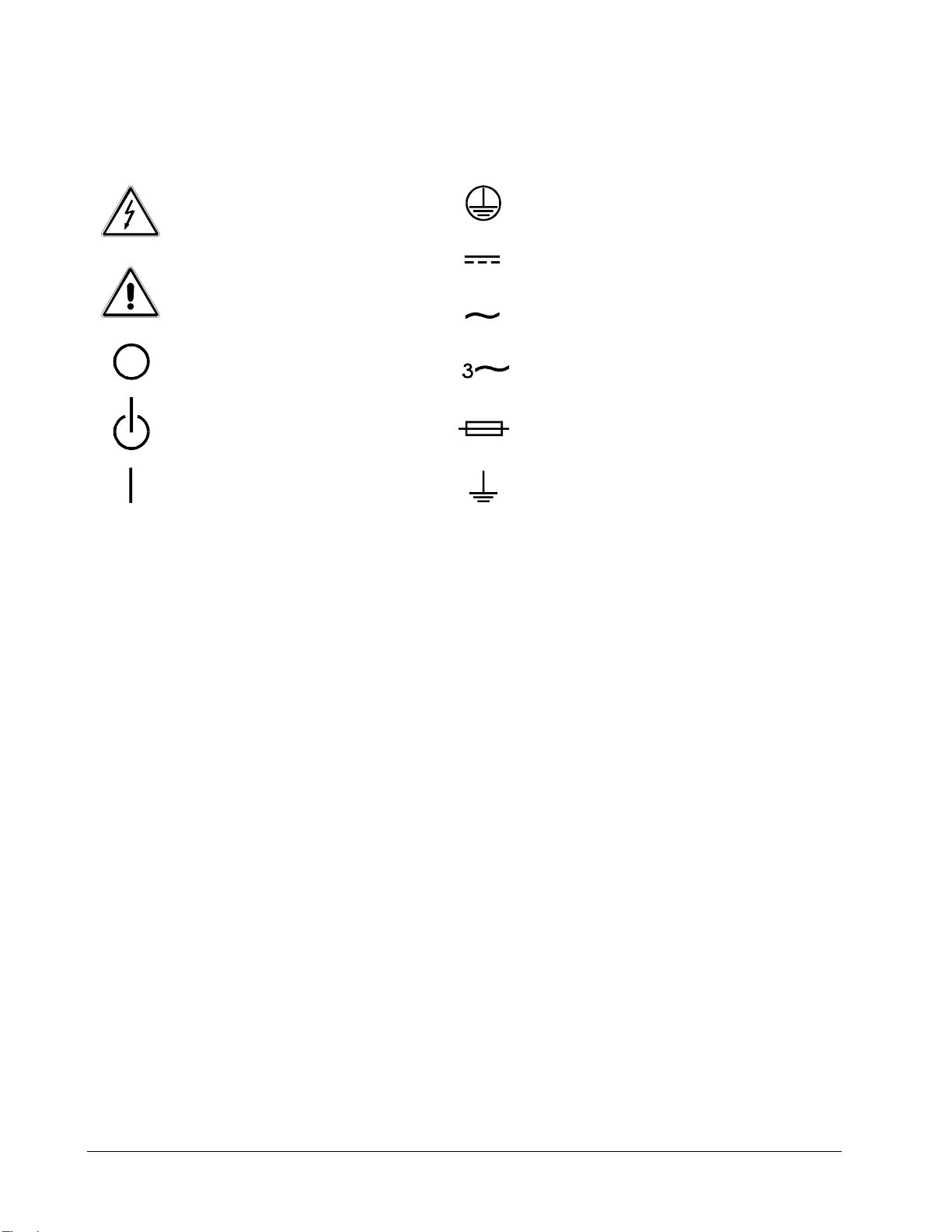
SAFETY SYMBOLS
CAUTION
Risk of Electrical Shock
CAUTION
Refer to Accompanying Documents
Off (Supply)
Standby (Supply)
On (Supply)
Direct Current (DC)
Alternating
Three–Phase
Fuse
Earth (Ground) Terminal
Protective Conductor Terminal
Current (AC)
Alternating Current
Artisan Scientific - Quality Instrumentation ... Guaranteed | (888) 88-SOURCE | www.artisan-scientific.com
Artisan Technology Group - Quality Instrumentation ... Guaranteed | (888) 88-SOURCE | www.artisantg.com

v
CONTENTS
1. GENERAL INFORMATION
1.1 Introduction .................................................................................................. 1-1
1.2 Description................................................................................................... 1-1
1.3 Overview of Key Features............................................................................ 1-1
1.4 Specifications............................................................................................... 1-2
2. INSTALLATION
2.1 Introduction .................................................................................................. 2-1
2.2 Inspection .................................................................................................... 2-1
2.3 Installing the Modules .................................................................................. 2-1
2.3.1 Channel Number.............................................................................. 2-2
2.4 Installing the Mainframe............................................................................... 2-3
2.4.1 Changing Line Voltage..................................................................... 2-3
2.4.2 Turn-On Self-Test ............................................................................ 2-4
2.5 Application Connection ................................................................................ 2-5
2.5.1 Load Connections ............................................................................ 2-5
2.5.2 Remote Sensing Connections.......................................................... 2-6
2.5.3 Parallel Connections ........................................................................ 2-7
2.6 Remote Control Connection......................................................................... 2-7
3. OPERATION OVERVIEW
3.1 Introduction .................................................................................................. 3-1
3.2 Front Panel Description ............................................................................... 3-1
3.3 Rear Panel Description ................................................................................ 3-2
3.4 Local/Remote Control .................................................................................. 3-2
3.5 Modes of Operation ..................................................................................... 3-3
3.5.1 Constant Current Mode.................................................................... 3-3
3.5.2 Constant Resistance Mode .............................................................. 3-6
3.5.3 Constant Voltage Mode.................................................................... 3-7
3.6 Load Synchronization .................................................................................. 3-8
3.7 Measurements ............................................................................................. 3-8
3.8 Slew Rate and Minimum Transient Time ..................................................... 3-8
3.9 Start/Stop Sink Current ................................................................................ 3-8
3.10 Short On/Off............................................................................................... 3-10
3.11 Load On/Off ............................................................................................... 3-10
Artisan Scientific - Quality Instrumentation ... Guaranteed | (888) 88-SOURCE | www.artisan-scientific.com
Artisan Technology Group - Quality Instrumentation ... Guaranteed | (888) 88-SOURCE | www.artisantg.com

Sorensen MML Series Operation and Programming Manual
vi
3.12 Protection Features ....................................................................................3-10
3.13 Save/Recall Setting ....................................................................................3-12
3.14 Program......................................................................................................3-12
4. LOCAL OPERATION
4.1 Introduction...................................................................................................4-1
4.2 Local Operation of Load Mainframe .............................................................4-1
4.1.1 Selecting the Channel ....................................................................4-3
4.1.2 Setting the Operation Mode............................................................4-3
4.1.3 Setting the Program........................................................................4-7
4.1.4 Running the Program ...................................................................4-10
4.1.5 Setting the Specifications .............................................................4-10
4.1.6 Setting the Configuration ..............................................................4-11
4.1.7 Recalling Files ..............................................................................4-15
4.1.8 Saving Files ..................................................................................4-15
4.1.9 Saving Defaults ............................................................................4-16
4.1.10 Saving Programs ..........................................................................4-16
4.1.11 Going To Local .............................................................................4-16
4.1.12 Lock Operation .............................................................................4-16
4.1.13 Setting System and RS-232C Connection....................................4-16
4.1.14 Connecting the GO/NG Output Port .............................................4-17
4.1.15 Setting the GPIB Address.............................................................4-17
4.3 Local Operation of Load Module ................................................................4-18
4.3.1 Local Operation of Single Channel/Module (Panel A) ..................4-18
4.1.2 Local Operation of Double Channels/Module (Panel B) ...............4-21
4.1.3 Online Change Level ....................................................................4-24
5. REMOTE OPERATION
5.1 Introduction...................................................................................................5-1
5.2 DIP Switches on the GPIB Card...................................................................5-1
5.2.1 GPIB Address...................................................................................5-1
5.2.2 Other DIP Switches ..........................................................................5-2
5.3 GPIB Capability of the Electronic Load.........................................................5-3
5.4 RS232C in Remote Control ..........................................................................5-3
5.5 Basic Programming Definitions ....................................................................5-4
5.6 Numerical Data Formats...............................................................................5-5
5.7 Character Data Formats ...............................................................................5-6
Artisan Scientific - Quality Instrumentation ... Guaranteed | (888) 88-SOURCE | www.artisan-scientific.com
Artisan Technology Group - Quality Instrumentation ... Guaranteed | (888) 88-SOURCE | www.artisantg.com

Contents
vii
5.8 Separators and Terminators ........................................................................ 5-6
5.9 Language Dictionary.................................................................................... 5-8
5.9.1 Common Commands ....................................................................... 5-8
5.10 Specific Commands ................................................................................... 5-13
5.10.1 ABORT Subsystem...................................................................... 5-13
5.10.2 CHANNEL Subsystem ................................................................. 5-13
5.10.3 CONFIGURE Subsystem............................................................. 5-16
5.10.4 CURRENT Subsystem................................................................. 5-21
5.10.5 FETCH Subsystem ...................................................................... 5-25
5.10.6 LOAD Subsystem ........................................................................ 5-27
5.10.7 MEASURE Subsystem ................................................................ 5-29
5.10.8 MODE Subsystem ....................................................................... 5-32
5.10.9 PROGRAM Subsystem................................................................ 5-33
5.10.10 RESISTANCE Subsystem ........................................................... 5-37
5.10.11 RUN Subsystem .......................................................................... 5-39
5.10.12 SHOW Subsystem ....................................................................... 5-39
5.10.13 SPECIFICATION Subsystem....................................................... 5-40
5.10.14 STATUS Subsystem .................................................................... 5-43
5.10.15 VOLTAGE Subsystem ................................................................. 5-48
5.11 Status Reporting ........................................................................................ 5-50
5.11.1 Introduction .................................................................................. 5-50
5.11.2 Register Information in Common ................................................. 5-50
5.11.3 Channel Status ............................................................................ 5-52
5.11.4 Channel Summary ....................................................................... 5-53
5.11.5 Questionable Status..................................................................... 5-53
5.11.6 Output Queue .............................................................................. 5-54
5.11.7 Standard Event Status ................................................................. 5-54
5.11.8 Status Byte Register .................................................................... 5-55
5.11.9 Service Request Enable Register ................................................ 5-55
6. PROGRAMMING EXAMPLE
Artisan Scientific - Quality Instrumentation ... Guaranteed | (888) 88-SOURCE | www.artisan-scientific.com
Artisan Technology Group - Quality Instrumentation ... Guaranteed | (888) 88-SOURCE | www.artisantg.com
Artisan Scientific - Quality Instrumentation ... Guaranteed | (888) 88-SOURCE | www.artisan-scientific.com
Artisan Technology Group - Quality Instrumentation ... Guaranteed | (888) 88-SOURCE | www.artisantg.com
1-1
1 GENERAL INFORMATION
1.1 Introduction
This manual contains specifications, installation, operation, and programming
instructions of MML-4, MML-2 electronic load mainframes as well as the
MML-80-20-102 and MML-80-60-301 electronic load modules. Here “Load” means the
electronic load modules of Sorensen MML series while “Mainframe” the MML-4, MML-2
electronic load mainframes.
1.2 Description
The functions of MML-4 and MML-2 mainframes are the same. The former has four
slots for Load modules while the latter two slots. The functions of MML-80-20-102,
MML-80-60-301, etc. are all the same. The differences are in input voltage, load
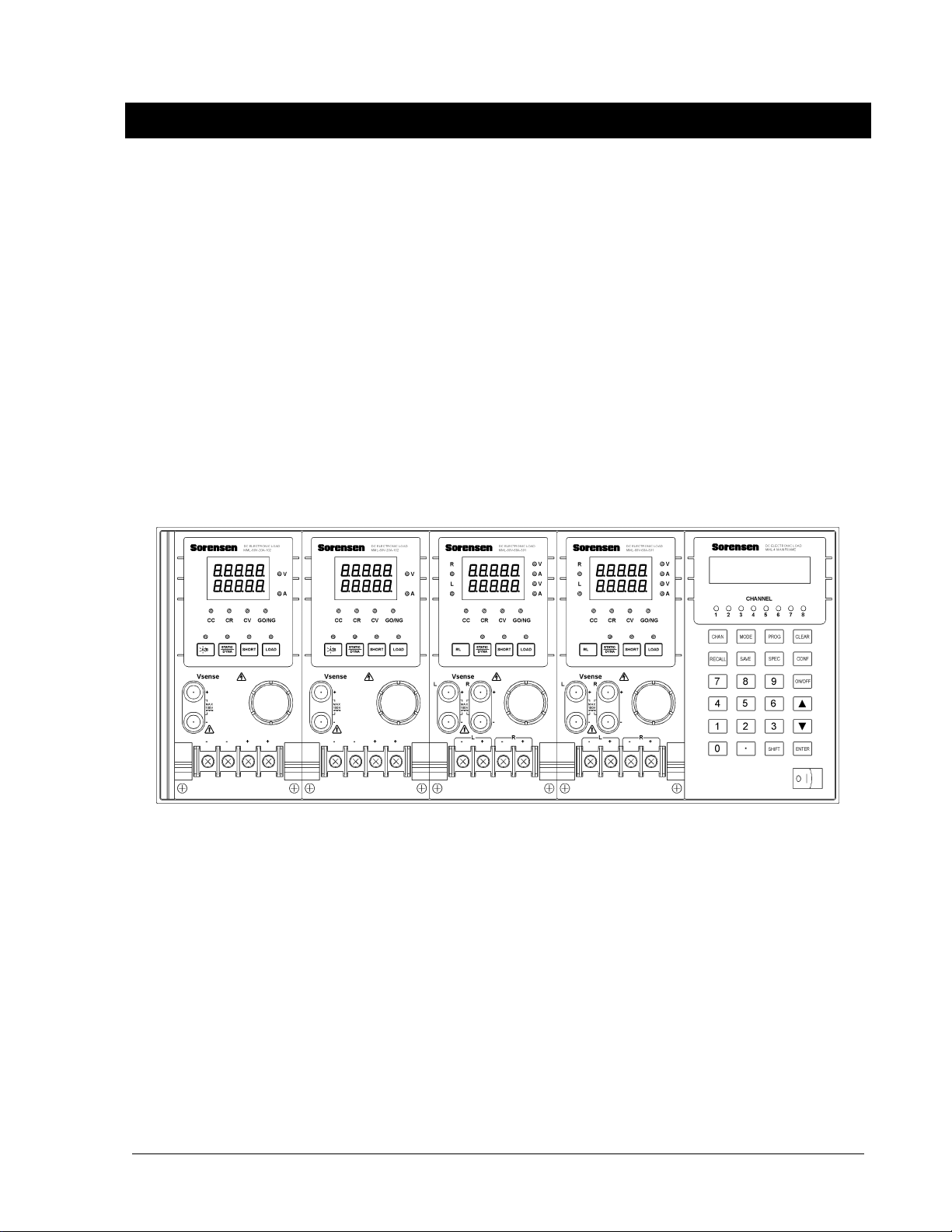
current, and power ratings. An individual module may have one or two channels.
Each channel has its own channel number, load and measurement connectors, and
operates independently in constant current (CC) mode, constant resistance (CR) mode,
or constant voltage (CV) mode.
Figure 1-1 Front Panel of the Electronic Load
There are two groups of keypads on the front panel of the electronic load (see Figure
1-1). One is the Mainframe keypad; the other is the Load keypad. In this manual, the
Mainframe keypad is referred to as MODE; the Load keypad is referred to as SHORT.
1.3 Overview of Key Features
1.3.1 Configuration
• Flexible configuration using plug-in electronic load modules to mainframes.
• Local operation on front panel keypad.
• Remote control via GPIB or RS-232C interface.
• Photocoupler isolation to offer true floating Load.
Artisan Scientific - Quality Instrumentation ... Guaranteed | (888) 88-SOURCE | www.artisan-scientific.com
Artisan Technology Group - Quality Instrumentation ... Guaranteed | (888) 88-SOURCE | www.artisantg.com

Sorensen MML Series Operation and Programming Manual
1-2
• Automatic fan speed control to reduce noise.
• Up to 8 channels for one Mainframe.
1.3.2 Load
• Constant current (CC), constant resistance (CR), and constant voltage (CV)
operation modes.
• Programmable slew rate, load levels, load periods, and conduct voltage (Von).
• Programmable dynamic loading with speed up to 20KHz.
• Minimum input resistance allowing load to sink high current even with low input
voltage (1 V).
• Selective voltage and current ranges.
• Remote sensing capability.
• 100 sets of memories to save/recall user-definable setups.
• 10 sets of programs to link files for automatic test.
• 15-bit A/D converter with precision measurement.
• Short circuit simulation.
• Automatic GO/NG inspection to confirm UUT within spec.
• Independent GO/NG signals for each channel.
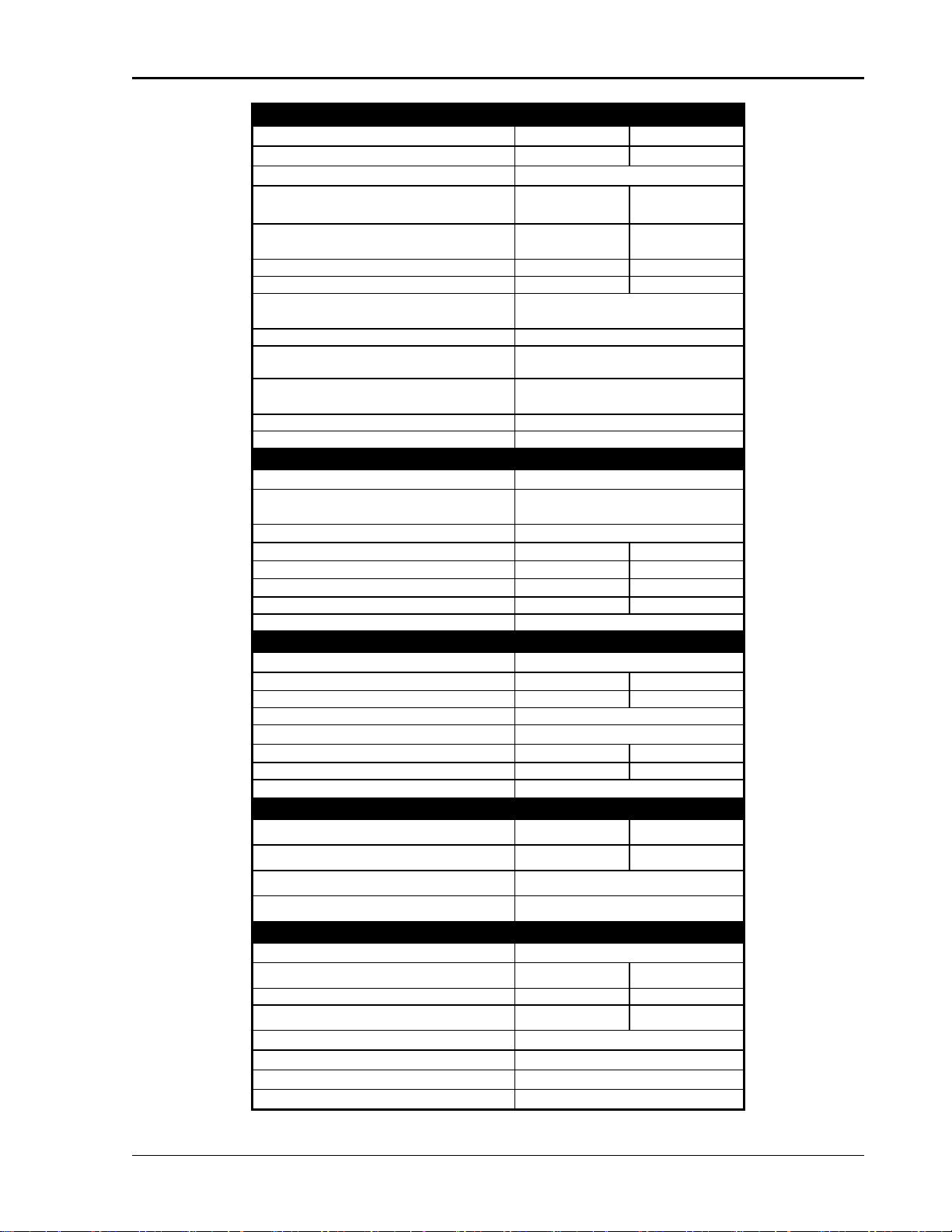
1.4 Specifications
Mainframe: MML-4
AC input: 115/230 switchable or 100/200 switchable Vac line
Fuse: 5A/250V
Amplitude: ±10%
Frequency: 47 to 63 Hz
Maximum VA: 180VA
Trigger output: Vlo = 0.8V maximum at Ilo = 1 mA
Vhi = 3.2V minimum at Ihi = −40µA
Weight: 24Kg
Dimensions: Width: 440mm
Height: 177.4 mm (excluding feet), 186mm (including feet)
Depth: 560mm (including Load module)
Load specifications are listed in the tables below.
NOTES
1. All specifications are tested at 20°C ∼30°C except otherwise stated.
2. The range of operation temperature is 0°C ∼40°C.
3. The specifications of DC current accuracy are tested after the input is applied for 30
seconds.
4. The power of the load module of MML series is supplied from MML-4/MML-2
mainframe.
5. The typical temperature coefficient is 100ppm.
Artisan Scientific - Quality Instrumentation ... Guaranteed | (888) 88-SOURCE | www.artisan-scientific.com
Artisan Technology Group - Quality Instrumentation ... Guaranteed | (888) 88-SOURCE | www.artisantg.com
General Information
1-3
MODEL MML-80-20-102(100W*2)
POWER 20W 100W
CURRENT 0∼2A 0∼20A
VOLTAGE 1∼80V
MINIMUM OPERATING VOLTAGE
(DC)
1.0V at 2A 1.0V at 20A
CONSTANT CURRENT MODE
Range
0∼2A 0∼20A
Resolution 0.5mA 5mA
Accuracy 0.1%+0.1%F.S. 0.1%+0.2%F.S.
CONSTANT RESISTANCE MODE
Range
CRL: (0.075Ω∼300Ω) (100W/16V)
CRH: (3.75Ω∼15KΩ) (100W/80V)
Resolution 12 bits
Accuracy CRL: 0.1mho+0.2%
CRH: 0.01mho+0.1%
CONSTANT VOLTAGE MODE
Range
1∼80V
Resolution 20mV
Accuracy 0.05%+0.1%F.S.
DYNAMIC MODE
DYNAMIC MODE C.C. MODE
T1 and T2 0.025mS∼10mS / Res: 1µS
1mS∼30S / Res: 1mS
Accuracy 1µS /1mS+100ppm
Slew Rate 0.32∼80mA/µS 3.2∼800mA/µS
Resolution 0.32mA/µS 3.2mA/µS
Current 0∼2A 0∼20A
Resolution 0.5mA 5mA
Current Accuracy 0.4% F.S.
MEASUREMENT SECTION
VOLTAGE READ BACK
Range 0∼16V 0∼80V
Resolution 0.5mV 2.5mV
Accuracy 0.05%+0.05% F.S.
CURRENT READ BACK
Range 0∼2A 0∼20A
Resolution 0.0625mA 0.625mA
Accuracy ±(0.1%+0.1% F.S.)
PROTECTIVE SECTION
Over Power Protection ≒20.8W ≒104W
Over Current Protection ≒2.04A ≒20.4A
Over Temperature Protection ≒85°C
Over Voltage Protection ≒81.6V/16.3V
GENERAL
SHORT CIRCUIT
Current (CC) ≒2.2/2A ≒22/20A
Voltage (CV) 0V 0V
Resistance (CR) ≒3.75Ω≒0.075Ω
INPUT RESISTANCE (LOAD OFF) 100KΩ(Typical)
SIZE 81(W)×172(H)×495(D)
WEIGHT (Approx.) 4.2Kg
EMC and SAFETY CE
Artisan Scientific - Quality Instrumentation ... Guaranteed | (888) 88-SOURCE | www.artisan-scientific.com
Artisan Technology Group - Quality Instrumentation ... Guaranteed | (888) 88-SOURCE | www.artisantg.com
Sorensen MML Series Operation and Programming Manual
1-4
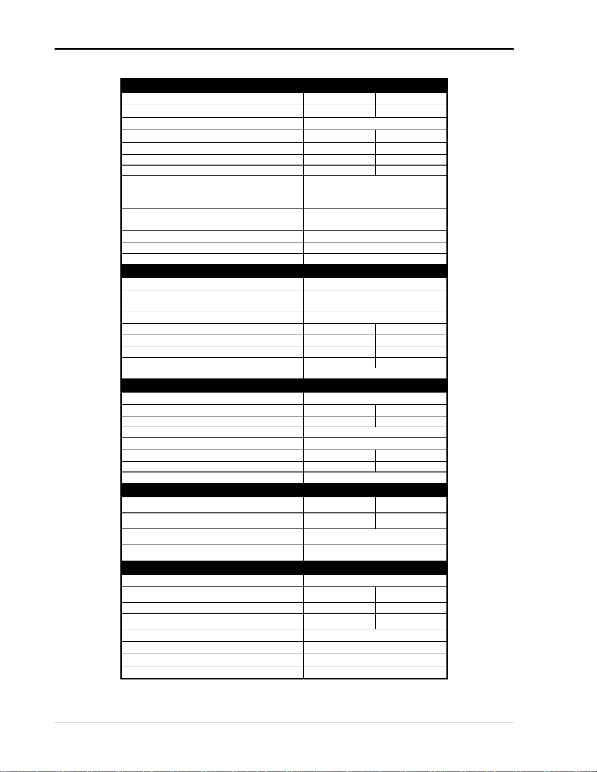
MODEL MML-80-60-301
POWER 30W 300W
CURRENT 0∼6A 0∼60A
VOLTAGE 1∼80V
MINIMUM OPERATING VOLTAGE (DC) 1.0V at 6A 1.0V at 60A
CONSTANT CURRENT MODE Range 0∼6A 0∼60A
Resolution 1.5mA 15mA
Accuracy 0.1%+0.1%F.S. 0.1%+0.2%F.S.
CONSTANT RESISTANCE MODE
Range
0.025Ω∼100Ω(300W/16V)
1.25Ω∼5KΩ(300W/80V)
Resolution 12 bits
Accuracy CRL (100Ω): 0.1mho+0.2%
CRH (5KΩ): 0.01mho+0.1%
CONSTANT VOLTAGE MODE Range 2.5∼500V
Resolution 20mV
Accuracy 0.05%+0.1%F.S.
DYNAMIC MODE
DYNAMIC MODE C.C. MODE
T1 and T2 0.025mS∼10mS / Res: 1µS
1mS∼30S / Res: 1mS
Accuracy 1µS /1mS+100ppm
Slew Rate 0.001∼0.25A/µS 0.01∼2.5A/µS
Resolution 0.001A/µS 0.01A/µS
Current 0∼6A 0∼60A
Resolution 1.5mA 15mA
Current Accuracy 0.4% F.S.
MEASUREMENT SECTION
VOLTAGE READ BACK
Range 0∼16V 0∼80V
Resolution 0.5mV 2.5mV
Accuracy 0.05%+0.05% F.S.
CURRENT READ BACK
Range 0∼6A 0∼60A
Resolution 0.1875mA 1.875mA
Accuracy ±(0.1%+0.1% F.S.)
PROTECTIVE SECTION
Over Power Protection ≒31.2W ≒312W
Over Current Protection ≒6.12A ≒61.2A
Over Temperature Protection ≒85°C
Over Voltage Protection ≒81.6V/16.3V
GENERAL
SHORT CIRCUIT
Current (CC) ≒6.6/6A ≒66/60A
Voltage (CV) 0V 0V
Resistance (CR) ≒1.25Ω≒0.025Ω
INPUT RESISTANCE (LOAD OFF) 100KΩ(Typical)
SIZE 81(W)×172(H)×495(D)
WEIGHT (Approx.) 4.2Kg
EMC and SAFETY CE
Artisan Scientific - Quality Instrumentation ... Guaranteed | (888) 88-SOURCE | www.artisan-scientific.com
Artisan Technology Group - Quality Instrumentation ... Guaranteed | (888) 88-SOURCE | www.artisantg.com

General Information
1-5
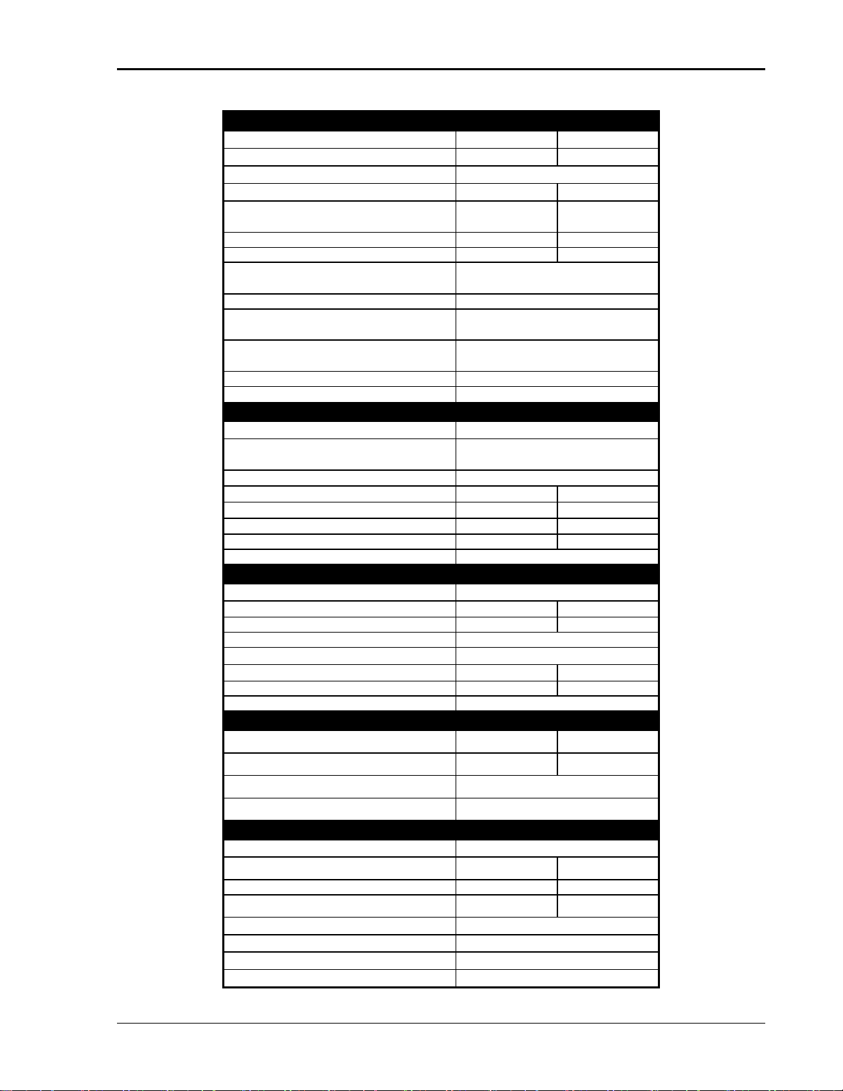
MODEL MML-80-120-601
POWER 60W 600W
CURRENT 0∼12A 0∼120A
VOLTAGE 1∼80V
MINIMUM OPERATING VOLTAGE (DC) 1.0V at 12A 1.0V at 120A
CONSTANT CURRENT MODE Range
0∼12A
0∼120A
Resolution 3mA 30mA
Accuracy 0.1%+0.1%F.S. 0.1%+0.2%F.S.
CONSTANT RESISTANCE MODE Range 0.0125Ω∼50Ω(600W/16V)
0.625Ω∼2.5KΩ(600W/80V)
Resolution 12 bits
Accuracy CRL (50Ω): 0.4mho+0.5% (top)
CRH (2.5KΩ): 0.04mho+0.2%
(bottom)
CONSTANT VOLTAGE MODE Range 1∼80V
Resolution 20mV
Accuracy ±(0.05%+0.1%F.S.)
DYNAMIC MODE
DYNAMIC MODE C.C. MODE
T1 and T2 0.025mS∼10mS / Res: 1µS
1mS∼30S / Res: 1mS
Accuracy 1µS /1mS+100ppm
Slew Rate 0.002∼0.5A/µS 0.02∼5A/µS
Resolution 0.002A/µS 0.02A/µS
Current 0∼12A 0∼120A
Resolution 3mA 30mA
Current Accuracy 0.4% F.S.
MEASUREMENT SECTION
VOLTAGE READ BACK
Range 0∼16V 0∼80V
Resolution 0.5mV 2.5mV
Accuracy 0.05%+0.05% F.S.
CURRENT READ BACK
Range 0∼12A 0∼120A
Resolution 0.375mA 3.75mA
Accuracy 0.1%+0.1% F.S.
PROTECTION SECTION
Over Power Protection ≒62.4W ≒624W
Over Current Protection ≒12.24A ≒122.4A
Over Temperature Protection ≒85°C
Over Voltage Protection ≒81.6V/16.3V
GENERAL
SHORT CIRCUIT
Current (CC) ≒13.2/12A ≒132/120A
Voltage (CV) 0V 0V
Resistance (CR) ≒0.625Ω≒0.0125Ω
INPUT RESISTANCE (LOAD OFF) 100KΩ(Typical)
SIZE 162(W)×172(H)×495(D)
WEIGHT (Approx.) 8.4Kg
EMC and SAFETY CE
Artisan Scientific - Quality Instrumentation ... Guaranteed | (888) 88-SOURCE | www.artisan-scientific.com
Artisan Technology Group - Quality Instrumentation ... Guaranteed | (888) 88-SOURCE | www.artisantg.com

Sorensen MML Series Operation and Programming Manual
1-6
MODEL MML-500-10-301
POWER 30W 300W
CURRENT 0∼1A 0∼10A
VOLTAGE 2.5∼500V
MIN. OPERATING VOLTAGE (DC) 2.5V at 1A 2.5V at 10A
CONSTANT CURRENT MODE
Range
0∼1A 0∼10A
Resolution 0.25mA 2.5mA
Accuracy 0.1%+0.1%F.S. 0.1%+0.2%F.S.
CONSTANT RESISTANCE MODE
Range
1.25Ω∼5KΩ(300W/125V)
50Ω∼200KΩ(300W/500V)
Resolution 12 bits
Accuracy 5KΩ: 0.02 mho+0.2%
200KΩ: 0.005 mho+0.1%
CONSTANT VOLTAGE MODE
Range
2.5∼500V
Resolution 125mV
Accuracy 0.05%±0.1%F.S.
DYNAMIC MODE
DYNAMIC MODE C.C. MODE
T1 & T2 0.025mS∼10mS / Res: 1µS
1mS∼30S / Res: 1mS
Accuracy 1µS /1mS+100ppm
Slew Rate 0.16∼40mA/µS 1.6∼400mA/µS
Resolution 0.16mA/µS 1.6mA/µS
Current 0∼1A 0∼10A
Resolution 0.25mA 2.5mA
Current Accuracy 0.4% F.S.
MEASUREMENT SECTION
VOLTAGE READ BACK
Range 0∼125V 0∼500V
Resolution 4mV 16mV
Accuracy 0.05%+0.05% F.S.
CURRENT READ BACK
Range 0∼1A 0∼10A
Resolution 0.032mA 0.32mA
Accuracy 0.1%+0.1% F.S.
PROTECTION SECTION
Over Power Protection ≒31.2W ≒312W
Over Current Protection ≒1.02A ≒10.2A
Over Temperature Protection ≒85°C
Over Voltage Protection ≒510V/127.5V
GENERAL
SHORT CIRCUIT
Current (CC) ≒1.1/1A ≒11/10A
Voltage (CV) 0V 0V
Resistance (CR) ≒50Ω≒1.25Ω
INPUT RESISTANCE (LOAD OFF) 100KΩ(Typical)
SIZE 81(W)×172(H)×495(D)
WEIGHT (Approx.) 4.2Kg
EMC & SAFETY CE
Artisan Scientific - Quality Instrumentation ... Guaranteed | (888) 88-SOURCE | www.artisan-scientific.com
Artisan Technology Group - Quality Instrumentation ... Guaranteed | (888) 88-SOURCE | www.artisantg.com
General Information
1-7
MODEL MML-500-20-601
POWER 60W 600W
CURRENT 0∼2A 0∼20A
VOLTAGE 2.5∼500V
MIN. OPERATING VOLTAGE (DC) 2.5V at 2A 2.5V at 20A
CONSTANT CURRENT MODE
Range
0∼2A 0∼20A
Resolution 0.5mA 5mA
Accuracy 0.1%+0.1%F.S. 0.1%+0.2%F.S.
CONSTANT RESISTANCE MODE
Range
0.625Ω∼2.5KΩ(600W/125V)
25Ω∼100KΩ(600W/500V)
Resolution 12 bits
Accuracy 2.5KΩ: 0.05mho+0.2%
100KΩ: 0.005mho+0.1%
CONSTANT VOLTAGE MODE
Range
2.5∼500V
Resolution 125mV
Accuracy 0.05%±0.1%F.S.
DYNAMIC MODE
DYNAMIC MODE C.C. MODE
T1 & T2 0.025mS∼10mS / Res: 1µS
1mS∼30S / Res: 1mS
Accuracy 1µS /1mS+100ppm
Slew Rate 0.32∼80mA/µS 3.2∼800mA/µS
Resolution 0.32mA/µS 3.2mA/µS
Current 0∼2A 0∼20A
Resolution 0.5mA 5mA
Current Accuracy 0.4% F.S.
MEASUREMENT SECTION
VOLTAGE READ BACK
Range 0∼125V 0∼500V
Resolution 4mV 16mV
Accuracy 0.05%+0.05% F.S.
CURRENT READ BACK
Range 0∼2A 0∼20A
Resolution 0.0625mA 0.625mA
Accuracy 0.1%+0.1% F.S.
PROTECTION SECTION
Over Power Protection ≒62.4W ≒624W
Over Current Protection ≒2.04A ≒20.4A
Over Temperature Protection ≒85°C
Over Voltage Protection ≒510V/127.5V
GENERAL
SHORT CIRCUIT
Current (CC) ≒2.2/2A ≒22/20A
Voltage (CV) 0V 0V
Resistance (CR) ≒25Ω≒0.625Ω
INPUT RESISTANCE (LOAD OFF) 100KΩ(Typical)
SIZE 162(W)×172(H)×495(D)
WEIGHT (Approx.) 8.4Kg
EMC & SAFETY CE
Artisan Scientific - Quality Instrumentation ... Guaranteed | (888) 88-SOURCE | www.artisan-scientific.com
Artisan Technology Group - Quality Instrumentation ... Guaranteed | (888) 88-SOURCE | www.artisantg.com

2-1
2 INSTALLATION
2.1 Introduction
This chapter discusses installation of the Load to the Mainframe, Load connections,
and unit self-tests, as well as application considerations.
2.2 Inspection
As soon as the instrument is unpacked, inspect any damage that might have occurred
in shipping. Keep all packing materials in case the Load or the Mainframe has to be
returned. If any damage is found, please file a claim with the carrier immediately. Do
not return the instrument to Sorensen without prior approval.
In additon to this manual, be sure that the following items have also been received with
your Mainframe and Load:
• Mainframe: Power Cord
• Load Module: Measurement and Load Cables
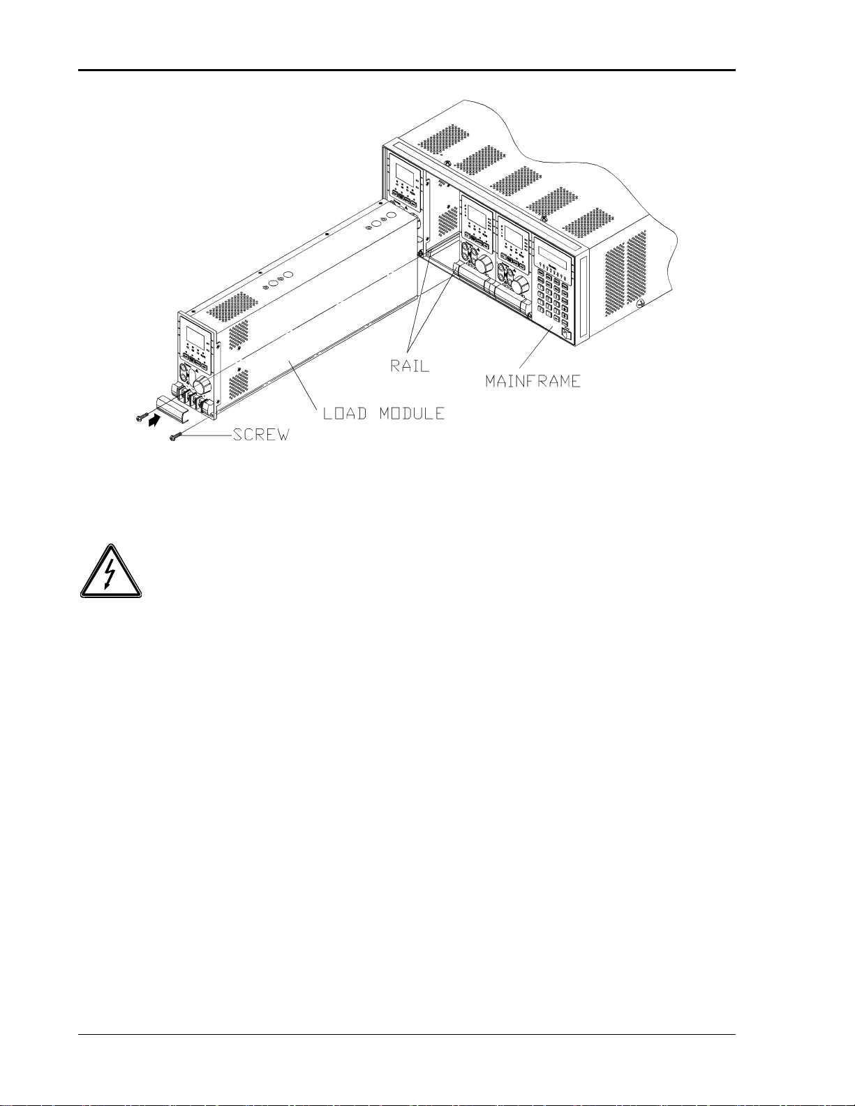
2.3 Installing the Modules
CAUTION!
Load module can be damaged by electronic discharge (static electricity).
Use standard anti-static work practices when you handle and install modules.
Avoid touching the connector and the circuit board.
The Sorensen MML-4 Mainframe can accommodate four single-width Loads
(MML-80-20-102, MML-80-60-301), or two double-width Loads (MML-80-120-601).
Loads can be combined in the Mainframe in any order. The Sorensen MML-2
mainframe can accommodate two single-width Loads or one double-width Load.
Module installation procedures in both Mainframes are the same. Installing Loads to
the Mainframe requires only a screwdriver.
Procedures
1. Disconnect the power cord with the Mainframe power off.
2. Remove any packing materials from the Mainframe.
3. Start installing the modules in the slot (see Figure 2-1).
4. Plug the load module into the slot of the Mainframe along the rail.
5. Lock the module in place by use of the screwdriver (see Figure 2-1).
6. Install each additional module in the slot next to the previous one.
Artisan Scientific - Quality Instrumentation ... Guaranteed | (888) 88-SOURCE | www.artisan-scientific.com
Artisan Technology Group - Quality Instrumentation ... Guaranteed | (888) 88-SOURCE | www.artisantg.com
Sorensen MML Series Operation and Programming Manual
2-2
Figure 2-1 Installing Modules in the Electronic Load
WARNING!
If the Mainframe is not installed with all modules, the empty module position
must be installed with the panel cover (Sorensen part no. 5361527-06) for safety
and airflow.
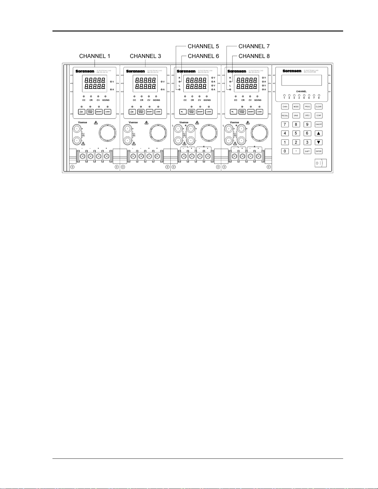
2.3.1 Channel Number
The channel number of a specific Load is determined by the location of that module in
relation to the farthest left side of Mainframe. Because some Load (MML-80-20-102)
has two channels in one module, channel 1 and 2 are always on the farthest left slot of
the Mainframe, and channel 7 and 8 on the farthest right. The channel number is fixed
for Mainframe even Load module is empty. Figure 2-2 shows the channel
assignments for a Sorensen MML-4 Mainframe containing two Loads of
MML-80-60-301 single channel/module, and two Loads of MML-80-20-102 double
channel/module. Channel number is automatically assigned to each channel: 1, 3, 5,
6, 7, 8. At this moment, channels 2 and 4 are empty. MML-2 Mainframe has only
four channels (1, 2, 3, 4).
Artisan Scientific - Quality Instrumentation ... Guaranteed | (888) 88-SOURCE | www.artisan-scientific.com
Artisan Technology Group - Quality Instrumentation ... Guaranteed | (888) 88-SOURCE | www.artisantg.com
Installation
2-3
Figure 2-2 Channel Number Example
2.4 Installing the Mainframe
The electronic Load operates properly within a temperature range of 0 to 40º C.
However, you must install the electronic Load in a location that has enough space at
the top, four sides, and the rear of the unit for adequate airflow. Leave at least 3 cm
(1 inch) above the unit for adequate air circulation. Note that the feet of the unit
provide vertical space for air circulation when it is stacked. The feet of the Mainframe
can be removed for rack mounting.
If you install equipment above the electronic Load in the cabinet, you must use a filter
panel above the unit to ensure adequate air circulation. A 1U (EIA standard) panel is
sufficient.
2.4.1 Changing Line Voltage
The electronic Load can operate with a 115/230 Vac input as indicated on the rear LINE
label. The 100/200 line voltage input model is used only in Japan. If the factory set
switch on this label does not correspond to your nominal line voltage, turn the
Mainframe power off, and disconnect the power cord. Set switch to the correct line
voltage as shown in Figure 2-3.
NOTE: Line fuses do not need to be changed when the line voltage is changed. The
line fuses will protect the electronic Load in any indicated voltage setting.
Artisan Scientific - Quality Instrumentation ... Guaranteed | (888) 88-SOURCE | www.artisan-scientific.com
Artisan Technology Group - Quality Instrumentation ... Guaranteed | (888) 88-SOURCE | www.artisantg.com
This manual suits for next models
6
Table of contents
Popular Industrial Electrical manuals by other brands


Murata
Murata GRM155C70J225KE11 Series Reference sheet

Murata
Murata GRM1555C1H121JA01 Series Reference sheet

Murata
Murata GRM0225C1E7R9WA03 Series Reference sheet

Siemens
Siemens 3TF68 Q Series operating instructions

Murata
Murata GRM219D71A475KE15 Series Reference sheet

Murata
Murata GRT31CR60J156KE01 Series Reference sheet

Murata
Murata GRM0335C1ER30WA01 Series Reference sheet

Murata
Murata GRM185R60J105KE26 Series Reference sheet

Multi-Mover
Multi-Mover XL35 User manual and parts list

OEZ
OEZ CS-BL-A015 Instructions for use

Murata
Murata GQM2195C2E1R8WB12 Series Reference sheet

Murata
Murata GRM31CR60J476ME19 Series Reference sheet