Sound Choice PCK-350 DR User manual

/
LR
USB
DVD
C +GD
POG AMR R
1234567890
O
PWER
O
PWER
MUSI C VOLMUSI C VOL
MI
C 1 MIC2
MIC 1 VO L MIC 2 VO LECHO
TAPE
AUXDV D /B C
P A KON VIDE OLR
AUX IN PUT
AUX
DVD
TAPE
P/B CKA
iPod
nOnO Of
fOf
f
BALA NCE
iPod
LR
O B
D L Y
D I G I T L
A
IGIT A D
D AL U IO
P CGRA HIS
N UI P T
®
PCK-350 DR
USER'S MANUAL
ALL-IN-ONE MUSIC SYSTEM
N eALL-in-O E Music Syst m
PCK-350 DR
Before operating this unit, please read this user's
manual completely and keep this manual for future reference.

Sound Choice® Accompaniment Tracks are arranged and produced to duplicate the
original hit recordings – both with and without the lead vocals! All songs are
recorded by our studio musicians in the same key and tempo as the original artist.
Songs include background vocals if found on the original recording.
Sound Choice songs are available on compact disc plus graphics (CDG) and as
digital downloads from various sites around the world. Visit www.soundchoice.com
and look for the music downloads link.
www.soundchoice.com
Also available are the Pro Mic 12 and Padded Carrying Bag for the PCK 350 DR.
Padded Carrying Bag for PCK 350 DR
Protect your investment with this attractive and
functional carrying bag for your PCK 350 DR. Made of
durable woven nylon fabric it has a padded front and a
large pocket in the back to hold your microphones,
cables, power cord and music. During storage and
transportation, the fabric keeps out dust, helps repel
moisture and resists scuffing, helping to keep your
player in top condition.
PRO MIC 12 with 10' Cable
Don't sing alone! Add a second or third matching
microphone that came with your PCK 350 DR
• Vocal Quality Dynamic Microphone
• Value Priced
• Extremely Durable Zinc Diecast Metal Body
• Unidirectional Pattern
• 10-Foot Detachable Mic Cable
• On/Off Switch
To sign up for our new release newsletter, browse new
releases or order additional products, go to:

TABLE OF CONTENTSTABLE OF CONTENTS
Warnings, Cautions and Others-----------------------------------Warnings, Cautions and Others-----------------------------------
Controls and Functions----------------------------------------------Controls and Functions----------------------------------------------
11
Play Modes-------------------------------------------------------------Play Modes-------------------------------------------------------------
Functions and Operations-------------------------------------------Functions and Operations-------------------------------------------
Setup -------------------------------------------------------------------Setup -------------------------------------------------------------------
Specifications --------------------------------------------------------Specifications --------------------------------------------------------
Troubleshooting -----------------------------------------------------Troubleshooting -----------------------------------------------------
1717
1818
2323
2626
2727
55
Brief Introduction----------------------------------------------------- 14Brief Introduction----------------------------------------------------- 14
USB/Memory Card Operation---------------------------------------15USB/Memory Card Operation---------------------------------------15
MP3 Player or iPod Playback ------------------------------------- 16MP3 Player or iPod Playback ------------------------------------- 16
TM
®
www.soundchoice.com
To sign up for our new release newsletter, browse new
releases or order additional products, go to:
For Canada/Pour le Canada
THIS DIGITALAPPARATUS DOES NOT EXCEED
THE CLASS B LIMITS FOR RADIO NOISE
EMISSIONS FORM DIGITALAPPARATUS AS SET
OUT IN THE INTERFERENCE-CAUSING
EQUIPMENT STANDARD ENTITLED DIGITAL
APPARATUS, ICES-003 OF THE DEPARTMENT
OF COMMUNICATIONS. CETAPPAREIL
NUMERIQUE RESPECTE LES LIMITES DE
BRUITS RADIO ELECTRIQUESAPPLICABLES
AUXAPPAREILS NUMERIQUES DE CLASSE B
PRESCRITES DANS LA NORMESUR LE
MATERIEL BROUILLEUR: APPAREILS
NUMERIQUES , NMB-003 EDICTEE PAR LE
MINISTRE DES COMMUNICATIONS.
""
" "
Caution
Disconnect the mains plug to shut the power off
completely. The POWER is not disconnected from
the mains line when the POWER button on the front
panel is pressed in.
Caution
Disconnect the mains plug to shut the power off
completely. The POWER is not disconnected from
the mains line when the POWER button on the front
panel is pressed in.
1. CLASS1 LASER PRODUCT
2. DANGER: Visible laser radiation when open and
interlock failed or defeated.Avoid direct exposure
to beam.
3. CAUTION: Do not open the top cover. There are
no user service able parts inside the unit. Leave
all servicing to qualified service personnel.
4. REPRODUCTION OF LABEL: CAUTION LABEL,
PLACED INSIDE THE UNIT.
IMPORTANT FOR LASER PODUCTSIMPORTANT FOR LASER PODUCTS
For Canada/Pour le Canada
CAUTION: TO PREVENT ELECTRIC SHOCK,
MATCH WIDE BLADE OF PLUG TO WIDE
SLOT,AND FULLY INSERT.
ATTENTION: POUR EVITER LES CHOCS
ELECTRIQUES, INTRODUIRE LA LAME LA PLUS
LARGE DE LA FICHE DANS LA BORNE
CORRESPONDANTE DE LA PRISE ET POUSSER
JUSQUAU FOND.
For Canada/Pour le Canada
CAUTION: TO PREVENT ELECTRIC SHOCK,
MATCH WIDE BLADE OF PLUG TO WIDE
SLOT,AND FULLY INSERT.
POUR EVITER LES CHOCS
ELECTRIQUES, INTRODUIRE LA LAME LA PLUS
LARGE DE LA FICHE DANS LA BORNE
CORRESPONDANTE DE LA PRISE ET POUSSER
JUSQUAU FOND.
ATTENTION:
PRODUCT COMPLIES WITH DHHS RULE 21
CFR SUB. CHAPTER J IN EFFECTAT DATE OF
MANUFACTURE.
COMPLIES WITH DHHS RADIATION
PERFORMANCE STANDARDS, 21 CFR SUB.
CHAPTER J.
PRODUCT COMPLIES WITH DHHS RULE 21
CFR SUB. CHAPTER J IN EFFECTAT DATE OF
MANUFACTURE.
COMPLIES WITH DHHS RADIATION
PERFORMANCE STANDARDS, 21 CFR SUB.
CHAPTER J.
CERTIFICATION:
THIS PRODUCT COMPLIES WITH FDA RADIATION
PERFORMANCE STANDARD, 21 CFR SUB.CHAPTER J.
CERTIFICATION:
THIS PRODUCT COMPLIES WITH FDA RADIATION
PERFORMANCE STANDARD, 21 CFR SUB.CHAPTER J.
1.This equipment has been tested and found to
comply with the limits for a Class B digital device,
pursuant to part 15 of the FCC Rules. These
limits are designed to provide reasonable
protection against harmful interference in a
residential installation.
This equipment generates, uses and can radiate
radio frequency energy and, if not installed and
used in accordance with the instructions, may
cause harmful interference to radio
communications. However, there is no guarantee
that interference will not occur in a particular
installation. If this equipment does cause harmful
interference to radio or television reception,
which can be determined by turning the
equipment off and on, the user is encouraged to
try to correct the interference by one or more of
the following measures:
*Reorient or relocate the receiving antenna.
*Increase the separation between the equipment
and receiver.
*Connect the equipment into an outlet on a circuit
different from that to which the receiver is
connected. Consult the dealer or an experienced
radio/TV technician for help.
2.IMPORTANT: When connecting this product to
accessories and/or another product use only
high quality shielded cables. Cable(s) supplied
with this product MUST be used. Follow all
installation instructions. Failure to follow
instructions could void your FCC authorization to
use product in the U. S. A.
FCC INFORMATION (U.S.A.)FCC INFORMATION (U.S.A.)
The lightning flash with arrowhead symbol, within an
equilateral triangle is intended to alert the user to the
presence of uninsulated dangerous voltage within the
product's enclosure that may be of sufficient magnitude
to constitute a risk of electric shock to persons.
The lightning flash with arrowhead symbol, within an
equilateral triangle is intended to alert the user to the
presence of uninsulated dangerous voltage within the
product's enclosure that may be of sufficient magnitude
to constitute a risk of electric shock to persons.
RISK OF ELECTRIC SHOCK
DO NOT OPEN
RISK OF ELECTRIC SHOCK
DO NOT OPEN
CAUTIONCAUTION
CAUTION: TO REDUCE THE RISK OF ELECTRIC SHOCK.
DO NOT REMOVE COVER (OR BACK).
NO USER SERVICEABLE PARTS INSIDE.
REFER SERVICING TO QUALIFIED SERVICE PERSONNEL.
CAUTION: TO REDUCE THE RISK OF ELECTRIC SHOCK.
DO NOT REMOVE COVER (OR BACK).
NO USER SERVICEABLE PARTS INSIDE.
REFER SERVICING TO QUALIFIED SERVICE PERSONNEL.
WARNING
To reduce the risk of fire or electrical shock, do not
expose this appliance to rain or moisture.
WARNING
To reduce the risk of fire or electrical shock, do not
expose this appliance to rain or moisture.
WARNINGS, CAUTIONS AND OTHERSWARNINGS, CAUTIONS AND OTHERS
The exclamation point within an equilateral triangle is
intended to alert the user to the presence of important
operating and maintenance (servicing) instructions in
the literature accompanying the appliance.
The exclamation point within an equilateral triangle is
intended to alert the user to the presence of important
operating and maintenance (servicing) instructions in
the literature accompanying the appliance.
Mises en garde, precautions et indications diversesMises en garde, precautions et indications diverses
11

2. Retain Instructions
The safety and operating instructions should be retained
for future reference. We also recommend you keep all
packing material and boxes in the event you have to ship
your unit in to a repair center.
2. Retain Instructions
The safety and operating instructions should be retained
for future reference. We also recommend you keep all
packing material and boxes in the event you have to ship
your unit in to a repair center.
Before using the unit, be sure to read all operating instructions carefully. Please note that
these are general precautions and may pertain to more than your unit.
Before using the unit, be sure to read all operating instructions carefully. Please note that
these are general precautions and may pertain to more than your unit.
1. Read Instructions
All the safety and operating instructions should be read
before the product is operated.
1. Read Instructions
All the safety and operating instructions should be read
before the product is operated.
3. Heed Warnings
All warnings on the product and in the operating
instructions should be adhered to.
3. Heed Warnings
All warnings on the product and in the operating
instructions should be adhered to.
4. Follow Instructions
All operating and use instructions should be followed.
4. Follow Instructions
All operating and use instructions should be followed.
5. Attachments
Do not use attachments not recommended by the
product manufacturer as they may cause hazards.
5. Attachments
Do not use attachments not recommended by the
product manufacturer as they may cause hazards.
6. Cleaning
Unplug this product from the wall outlet before cleaning.
Do not use liquid cleaners or aerosol cleaners. Use a dry
cloth for cleaning.
6. Cleaning
Unplug this product from the wall outlet before cleaning.
Do not use liquid cleaners or aerosol cleaners. Use a dry
cloth for cleaning.
8. Heat
The appliance should be situated away from heat
sources such as radiators, heat register, stoves, or other
apparatus (including amplifiers) that produce heat.
8. Heat
The appliance should be situated away from heat
sources such as radiators, heat register, stoves, or other
apparatus (including amplifiers) that produce heat.
9. Water and Moisture
Do not use this unit near water. For example, near a
bathtub or in a wet basement and the like.
9. Water and Moisture
Do not use this unit near water. For example, near a
bathtub or in a wet basement and the like.
10. Power-cord Protection
Power-supply cords should be routed so that they are
not likely to be walked on or pinched by items placed
upon or against them, paying particular attention to
cords at plugs, convenience receptacles, and point
where they exit from the appliance.
10. Power-cord Protection
Power-supply cords should be routed so that they are
not likely to be walked on or pinched by items placed
upon or against them, paying particular attention to
cords at plugs, convenience receptacles, and point
where they exit from the appliance.
11. Lightning
To protect your product from a lightning storm, or when it
is left unattended and unused for long periods of time,
unplug it from the wall outlet and disconnect the antenna
or cable system. This will prevent damage to the product
due to lightning and power-line surges.
11. Lightning
To protect your product from a lightning storm, or when it
is left unattended and unused for long periods of time,
unplug it from the wall outlet and disconnect the antenna
or cable system. This will prevent damage to the product
due to lightning and power-line surges.
7. Ventilation
The appliance should be situated so its location does not
interfere with its proper ventilation. For example, the
appliance should not be situated on a bed, sofa, rug, or
similar surface that may block the ventilation slots.
7. Ventilation
The appliance should be situated so its location does not
interfere with its proper ventilation. For example, the
appliance should not be situated on a bed, sofa, rug, or
similar surface that may block the ventilation slots.
12. Carts and Stands
The product should be used only with a cart
or stand that is recommended by the
manufacturer.
12. Carts and Stands
The product should be used only with a cart
or stand that is recommended by the
manufacturer.
12 A. An applicance and cart combination should be moved
with care. Quick stops, excessive force and uneven
surfaces may cause the appliance and cart combination
to overturn.
12 A. An applicance and cart combination should be moved
with care. Quick stops, excessive force and uneven
surfaces may cause the appliance and cart combination
to overturn.
13. Power Sources
product should be operated only from the type of power
source indicated on the marking label. If you are not
sure of the type of power supply to your home, consult
your product dealer or local power company.
13. Power Sources
product should be operated only from the type of power
source indicated on the marking label. If you are not
sure of the type of power supply to your home, consult
your product dealer or local power company.
14. Grounding and Polarization
This product is equipped with a polarized alternating-
current line plug (a plug having one blade wider than the
other). This plug will fit into the power outlet only one
way. This is a safety feature. If you are unable to insert
the plug fully into the outlet, try reversing the plug. If the
plug should still fail to fit, contact your electrician to
replace your obsolete outlet. Do not defeat the safety
purpose of the polarized plug.
15. Power Lines
An outside antenna system should not be located in the
vicinity of overhead power lines or other electric light or
power circuits, or where it can fall into such power lines
or circuits. When installing an outside antenna system,
extreme care should be taken to keep from touching
such power lines or circuits as contact with them might
be fatal.
16. Overloading
Do not overload wall outlets, extension cords, or integral
convenience receptacles as this can result in a risk of
fire or electric shock.
16. Overloading
Do not overload wall outlets, extension cords, or integral
convenience receptacles as this can result in a risk of
fire or electric shock.
17. Object and Liquid Entry
Never push objects of any kind into this product through
openings as they may touch dangerous voltage points or
short-out parts that could result in a fire or electric
shock. Never spill liquid of any kind on the product.
17. Object and Liquid Entry
Never push objects of any kind into this product through
openings as they may touch dangerous voltage points or
short-out parts that could result in a fire or electric
shock. Never spill liquid of any kind on the product.
18. Replacement Parts
When replacement parts are required, be sure the
service technician has used replacement parts specified
by the manufacturer or have the same characteristics as
the original part. Unauthorized substitutions may result
in fire, electric shock, or other hazards.
18. Replacement Parts
When replacement parts are required, be sure the
service technician has used replacement parts specified
by the manufacturer or have the same characteristics as
the original part. Unauthorized substitutions may result
in fire, electric shock, or other hazards.
19. Safety Check
Upon completion of any service or repairs to this
product, ask the service technician to perform safety
checks to determine that the product is in proper
operating condition.
19. Safety Check
Upon completion of any service or repairs to this
product, ask the service technician to perform safety
checks to determine that the product is in proper
operating condition.
20. Outdoor Antenna Grounding
If an outside antenna or cable system is connected to the
product, be sure the antenna or cable system is
grounded so as to provide some protection against
voltage surges and built-up static charges. Article 810 of
the National Electrical Code, ANSI/NFPA 70, provides
information with regard to proper grounding of the mast
and supporting structure, grounding of the lead-in wire to
an antenna discharge unit, size of grounding conductors,
location of antenna discharge unit, connection to
grounding electrodes, and requirements for the
grounding electrode. See figure below.
22
SAFETY INSTRUCTIONSSAFETY INSTRUCTIONS

Note to CATV system installer
This reminder is provided to call the CATV system installers attention toArticle 820-40
of the NEC that provides guidelines for proper grounding and, in particular, specifies
that the cable ground shall be connected to the grounding system of the building, as
close to the point of cable entry as practical.
21. Damage Requiring Service
Unplug this product from the wall outlet and refer
servicing to qualified service personnel under the
following conditions:
A. When the power supply cord or plug is damaged.
B. If liquid has been spilled, or objects have fallen into
the product.
C. If the product has been exposed to rain or water.
D. If the product does not operate normally by following
the operating instructions. Adjust only those controls
that are covered by the operating instructions as an
improper adjustment of other controls may result in
damage and will often require extensive work by a
qualified technician to restore the product to its normal
operation.
E. If the product has been dropped or damaged in any
way.
F. When the product exhibits a distinct change in
performance-this indicates a need for service.
22. Servicing
Do not attempt to service it yourself as operating
instructions, do not attempt to service it yourself as
opening or removing covers may expose you to
dangerous voltage or other hazards. Refer all servicing
to qualified service personal.
22. Servicing
Do not attempt to service it yourself as operating
instructions, do not attempt to service it yourself as
opening or removing covers may expose you to
dangerous voltage or other hazards. Refer all servicing
to qualified service personal.
33
®
www.soundchoice.com
To sign up for our new release newsletter, browse new
releases or order additional products, go to:

44
TO OBTAIN SERVICE ON WARRANTY UNITS
Call Sound Choice customer service below for the nearest authorized warranty
service center. If there is no service center near you, then the unit must be sent
prepaid by insured parcel post or UPS to the Sound Choice service center address
nearest you. To establish eligibility for free repair or replacement, YOU MUST
INCLUDE A NOTE EXPLAINING HOW THE UNIT IS DEFECTIVE, a copy of the
original receipt (including the date), your full name, complete mailing address and
telephone number including area code.
North America
Sound Choice
Attn: Service Dept.
14100 South Lakes Drive
Charlotte, NC 28273
USA
Customer Service: 800-788-4487
or 704-583-1616 Ext. 1182
Australia
Sound Choice Distr. (Aust) Pty. Ltd.
Attn: Service Dept.
311 North East Road
Hampstead Gardens, SA 5086
AUSTRALIA
Customer Service: +61 (8) 8261-0566
IF THIS UNIT IS OUTSIDE OF THE WARRANTY PERIOD, please call the
appropriate number below for repair.
Note: The unit must be shipped in the original carton and placed inside
another carton with added padding for extra protection during shipment. All
original accessories including but not limited to cables, remote control,
batteries, owner’s manual, microphone and cable must be included or the
warranty will be voided. If the unit is missing parts when received in our
warehouse you may be charged by Sound Choice for all missing parts.
Limited WarrantyLimited Warranty
www.soundchoice.com
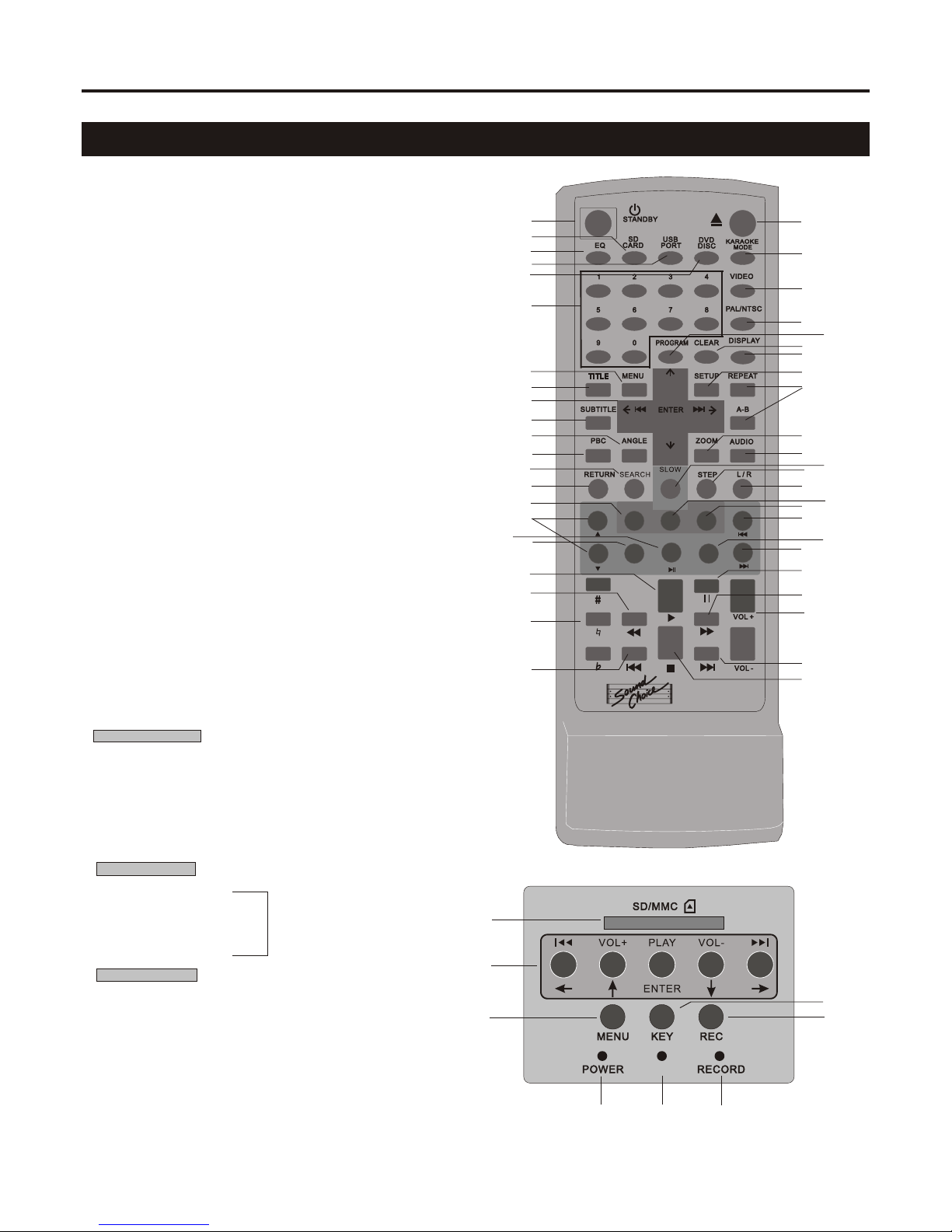
Remote Control FunctionsRemote Control Functions
CONTROLS & FUNCTIONSCONTROLS & FUNCTIONS
55
MENU
ENTER
IPOD CONTROLIPOD CONTROL
EDITEDIT
KEY /CLEA RKEY /CLEA R
MENU
VOL+VOL+
VOL -VOL -
RECREC
PCK-350 DRPCK-350 DR
1
2
3
4
5
6
7
8
9
10
11
12
13
14
15
16
1718
19
20
21
22
23
24
25
2627
28
29
30
31
32
3334
35
3637
38
39
41
42
43
44
45
46
40
P/BACK
1
2
3
456
7
8
1.Power (Standby)
2.SD card Mode
3.Equaliser Adjustment
4.USB Mode
5.DVD / Disc mode
6.Track Selection (Numbers)
7.DVD Menu
8.Title Selection
9.Selection Group (Vol, FF, RW Etc.)
10.Subtitle On / Off
11.Angle (Camera Selection)
12.PBC (Play Back Control)
13.Search
14.Return to PBC
19.Play
20.Rewind
21.Key Change
22.Previous Chapter / track
23.Open / Close
24.Karaoke Mode (Single Play Stops After Each Track)
25.Video Output Mode
26.Pal / NTSC
27.Program
28.Clear Program
29.Playback Information (on screen)
30.System Setup
31.Repeat (One / All etc. )
32.Zoom
33. Audio Settings
34.Slow
35.Step
36.L / R Audio (Multiplex)
42.Pause
43.Fast Forward
44.Adjust Player Volume Output
45.Next Chapter / track
46.Stop
Please Note: It is necessary to switch the PBC control to “OFF”
in order to operate the remote control on DVD playback.
To switch between Digital Recorder Playback and all other functions
refer to page 1 for switch location.
Digital Recorder
9. Select tracks to play on Digital Recorder
15 Key / Clear
34.Previous Menu
37.Edit
38.Record
IPOD Playback
16.Mouse (Up and Down)
17.Play / Pause
18.Enter
39.Previous Chapter / Track
40.Previous Menu
41.Next Chapter / Track
Digital Recorder
1.SD/MMC Mini SD (with adaptor) slot.
2.Press for previous track - hold for rewind current track.
3.Menu Select
4.Main power ON light
5.Playback mode light
6.Recording indicator light.
7.Key change
8.Recording
When the yellow (P/Back) light is ON all functions are
available. When it is OFF, you can only record from other
inputs (DVD, Tape,Aux etc.)
®
Note: Not activated for
Model PCK350 DR
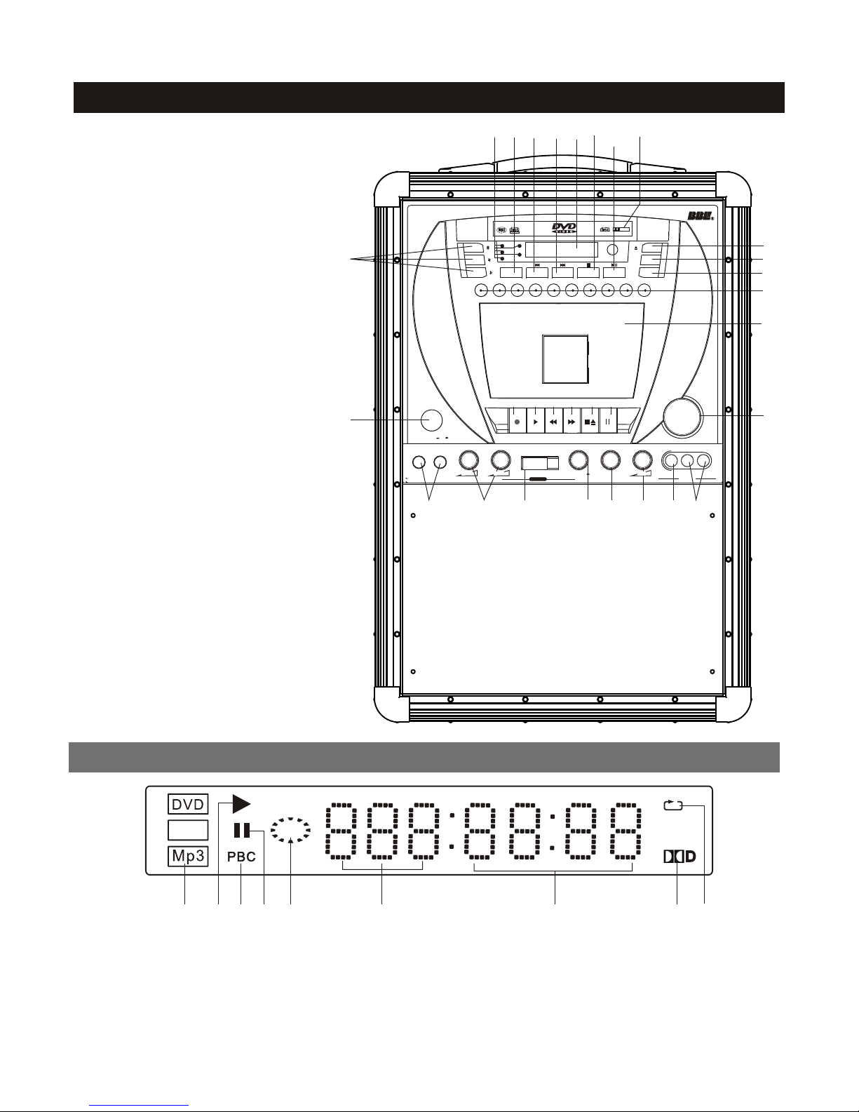
LED Display WindowLED Display Window
Front Panel FunctionsFront Panel Functions
66
VCD
114422335566778899
1.Disc type
2.In PLAY status
3.PBC on
4.In Pause status
5.Playback
1.Disc type
2.In PLAY status
3.PBC on
4.In Pause status
5.Playback
11
4343
1. Power ON/OFF
2.DVD/USB switch
3. Eject
11. LEFT/RIGHT channel
12. Numeric keys 0-9
15. CDG disc program
28/29. Play/Pause
30. Stop
34. Previous
35. Next
43. Key control
45. Tray door
46. LED display window
47. Microphone jacks
48. Microphone volume control
50. Function selector
51. Digital Record function
52. Function indicators
53. Music volume control
54. L/R Balance control
55. Echo control knob
56.AUX video input jack
57.AUX audio input jack
58. Cassette door
59. Record for tape
60. Play for tape
61. Fast backward for tape
62. Fast forward for tape
63. Stop/Eject for tape
64. Pause for tape
3434 3030
33
1111
22
1212
1515 3535 4646 4545
28/2928/29
5252
5858
5353
5959 6060 6161 6262 6363 6464
4747 4848 51515050 5454 5555 5656 5757
L/R
USB
DVD
CD+G
PROG RAM
12 3 45678 9 00
POWER
MUSIC VOL
MIC 1 MIC 2 MIC 1 V OL MI C 2 VOL ECH O
TAPE
AUX DVD P/BACK ON VIDEO L R
AUX I NPUT
AUX
DVD
TAPE
P/BACK
iPod
On Off
BALANCE
iPod
L R
DOLB YDOLB Y
D I G I T A LD I G I T A L
DIGITAL AUDIO
GRAPHICS
INPUT
6.Tray information
7.Time information
8.Dolby on
9.In Repeat status.
6.Tray information
7.Time information
8.Dolby on
9.In Repeat status.

L/R
USB
DVD
CD+G
PROGRAM
12 3 45678 9 0
Musicarrier
POWER
MUSIC VO L
MIC1 MIC 2 MIC 1 V OL MIC 2 V OL ECHO
TAPE
AUX DVD BBE ON VIDEO L R
AUXI NPU T
AUX
DVD
TAPE
BBE
iPod
On Off
BALANC E
iPod
L R
ALL- in-ONE M usic S ystem
DOLBY
D I G I T A L
DIGITALAUDIO
GRAPHICS
INPUT
77
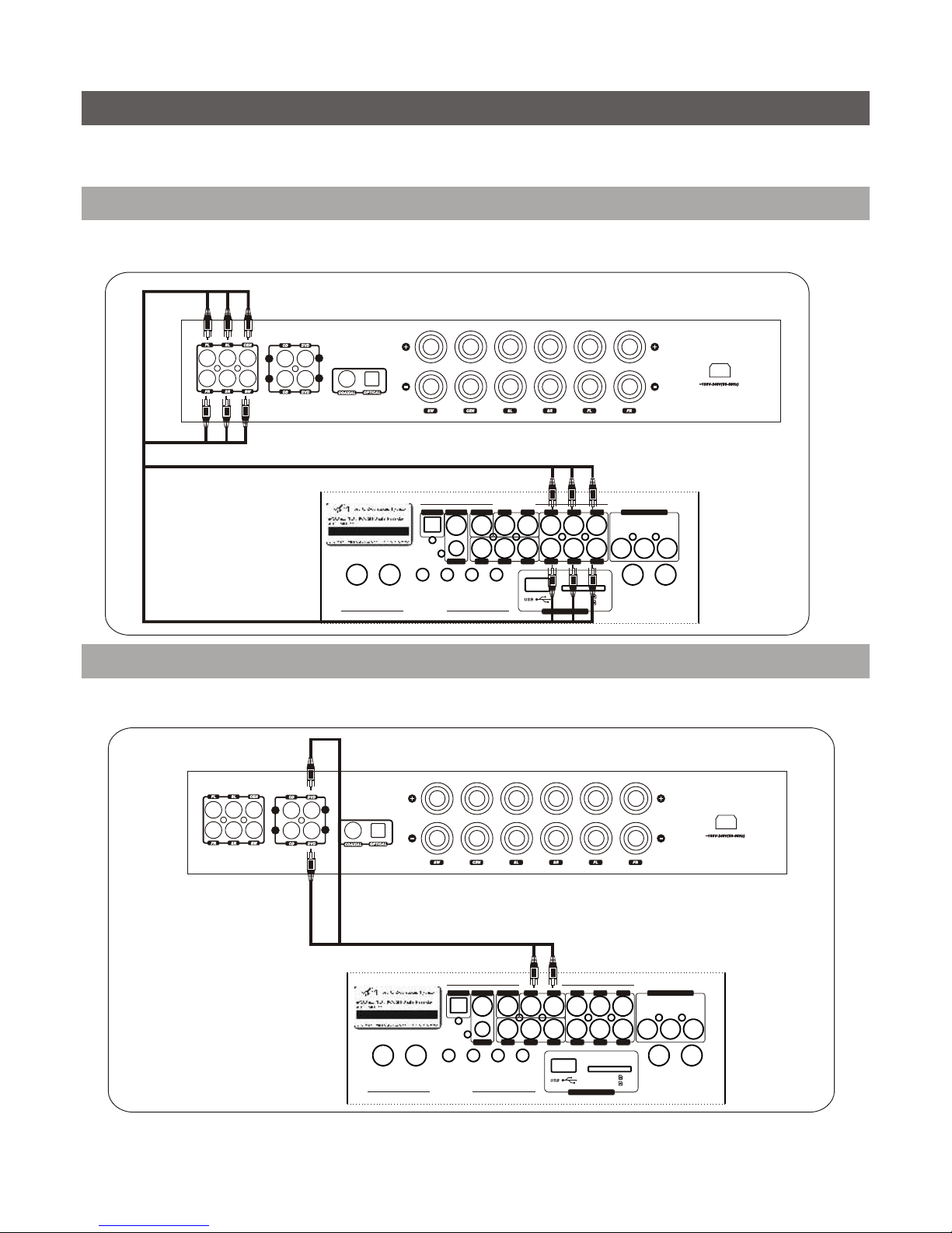
Rear Panel FunctionsRear Panel Functions
Microphone ConnectionMicrophone Connection
ConnectionConnection
1. 5.1 channel output jacks
2. R.G.B Video output jacks
3. DVD Video output jack
4. 2 channel output jacks
5. Coaxial output jack
6. S-VIDEO output jack
7. Optical output jack
8. Composite video output
9. Composite audio output
10. Power cord connector
11. Power selector
12. Fuse holder
13. Guitar input jacks
14. Guitar volume control
15. Guitar tone control
16. USB jack
17. Memory card slots
18. Rear panel mic input jacks
There are a total four microphone jacks on the machine,
two in the front panel and two in the back panel.
Plug the microphone cable into a jack.
There are a total four microphone jacks on the machine,
two in the front panel and two in the back panel.
Plug the microphone cable into a jack.
77
Y/RPB/GPR/B
VIDE O SW FLFR
SLSR
CENCOAXIAL MLMR
S-VI DEOOPTICAL
VIDE O
OUTPUT RL
GUITAR 1 GUITAR 2 GUITAR VOL BASS MID TR EBLE MIC 1 MI C2
SD/MMC
MIN I SD
FUSE 2. 5A/2 50V POW ER SEL ECT POW ER INPU T
AC110 V/AC23 0V 50/ 60Hz
RISK OF ELECTRIC SHOCK
DO NOT OPEN
CAUTION
DVD FUNC TION
OUTPUT
AUD IO OUT PUT
GUITAR FUNCT ION
DVD FUNC TION
6633
1212
2244118899
1818
1717
1616
15151414
1313
1111 1010
55

LL
RR
LL
RR
88
Home Theatre ConnectionHome Theatre Connection
FLFL FRFR
CENCEN
SWSW
TVTV
SLSL SRSR
5.1 Channel AV Amplifier5.1 Channel AV Amplifier
Y/RPB/GPR/B
VIDEO SW FLFR
SLSR
CENCOAXIAL MLMR
S-VI DEOOPTICAL
VIDEO
OUTPUT RL
GUI TAR 1 GUI TAR 2 GUI TAR VOL BAS S MID TRE BLE MIC 1 MIC 2
SD/M MC
MINI S D
FUS E 2.5A/ 250V POWER SEL ECT POW ER INP UT
AC110 V/AC23 0V 50/ 60Hz
RISK OF ELECTRIC SHOCK
DO NOT OPEN
CAUTION
DVD FU NCT ION
OUTPUT
AUD IO OUT PUT
GUI TAR FUNCT ION
DVD FU NCT ION

Y/RPB/GPR/B
VIDEO SW FLFR
SLSR
CENCOAXIAL MLMR
S-VIDEOOPTICAL
VIDEO
OUTPUT RL
GUITAR 1 GUITAR 2 GUITAR VOL BASS MID TREBLE MIC 1 MIC 2
SD/MMC
MINI SD
DVD FUNC TION
OUTPUT
AUDIO OU TPUT
GUITAR FUNCTION
DVD FUNC TION
POWER INPUTPOWER INPUT
AC110V/AC230V 50/60HzAC110V/AC230V 50/60Hz
11
1. Connect the power cable to the DVD player first.
2. Connect the power plug to the outlet.
1. Connect the power cable to the DVD player first.
2. Connect the power plug to the outlet.
99
Power Cord ConnectionPower Cord Connection
AC120V/240V
50Hz/60Hz
AC120V/240V
50Hz/60Hz 22
Composite Video Output ConnectionComposite Video Output Connection
TO-TV VIDEO INTO-TV VIDEO IN
NOTE: Check applicable voltage for your country.NOTE: Check applicable voltage for your country.
WARNING: Switch power button to OFF when finished using the machine.
Unplug the power cord if you will not be using the machine for a long time.
WARNING: Switch power button to OFF when finished using the machine.
Unplug the power cord if you will not be using the machine for a long time.
Y/RPB/GPR/B
VIDEO SW FLFR
SLSR
CENCOAXI AL MLMR
S-VIDEOOPTICAL
VIDEO
OUTPUT RL
GUITAR1 GUITAR 2 GUITAR VOL BASS MID TREBL E MIC1 MIC2
SD/MMC
MINI SD
FUSE2. 5A/2 50V POWER SEL ECT POWER IN PUT
AC110V/AC2 30V 5 0/60Hz
RISKOF ELECTRIC SHOCK
DONOT OPEN
CAUTION
DVDFUNC TION
OUTPUT
AUDIO OUTPUT
GUITARFUN CTIO N
DVDFUNC TION
Apply Video Cord (the one with yellow head) to connect VIDEO OUT jack on the PCK-350 DR with
VIDEO IN jack on TV.
Apply Video Cord (the one with yellow head) to connect VIDEO OUT jack on the PCK-350 DR with
VIDEO IN jack on TV.
NOTE: This is only applied to a standard TV with AV function while playing disc.NOTE: This is only applied to a standard TV with AV function while playing disc.

TO TV S-VIDEO INTO TV S-VIDEO IN
S-VIDEO ConnectionS-VIDEO Connection
Apply S-VIDEO Cord to connect S-VIDEO OUTPUT jack on PCK 350 DR with S-VIDEO IN jack on TV.
The TV should be set in S-VIDEO mode. Player setting is shown on PAGE 18.
Apply S-VIDEO Cord to connect S-VIDEO OUTPUT jack on PCK 350 DR with S-VIDEO IN jack on TV.
The TV should be set in S-VIDEO mode. Player setting is shown on PAGE 18.
1010
Y.Pb.Pr ConnectionY.Pb.Pr Connection
TO-TV Y.Pb.Pr INTO-TV Y.Pb.Pr IN
TV should be set in Y.Pb.Pr mode. For player setting, please see PAGE 18.TV should be set in Y.Pb.Pr mode. For player setting, please see PAGE 18.
Y/RPB/GPR/B
VIDEO SW FLFR
SLSR
CENCOAXIAL MLMR
S-VIDEOOPTICAL
VIDEO
OUTPUT RL
GUITAR 1 GUITAR 2 GUITAR VOL BASS MID TREBLE MIC 1 MIC 2
SD/MMC
MINI SD
DVD FUNC TION
OUTPUT
AUDIO OU TPUT
GUITAR FUNCTION
DVD FUNC TION
Y/RPB/GPR/B
VIDEO SW FLFR
SLSR
CENCOAXIAL MLMR
S-VIDEOOPTICAL
VIDEO
OUTPUT RL
GUITAR 1 GUITAR 2 GUITAR VOL BASS MID TREBLE MIC 1 MIC 2
SD/MMC
MINI SD
DVD FUNC TION
OUTPUT
AUDIO OU TPUT
GUITAR FUNCTION
DVD FUNC TION
Apply Y.Pb.Pr cords to connect Y.Pb.Pr jacks on Musicarrier with Y.Pb.Pr IN jacks on the TV.Apply Y.Pb.Pr cords to connect Y.Pb.Pr jacks on Musicarrier with Y.Pb.Pr IN jacks on the TV.

TO TV VIDEO INTO TV VIDEO IN
AUX Video Output ConnectionAUX Video Output Connection
1111
AUX In ConnectionAUX In Connection
Auxiliary video output for external video source. Also you can get composite video outputand video output
from iPod .
Auxiliary video output for external video source. Also you can get composite video outputand video output
from iPod .
PCK-350 DR canplay video and audio from external sourcethrough AUX IN jacks.TheFunctionSelector
must be switched to AUXstatus.
PCK-350 DR canplay video and audio from external sourcethrough AUX IN jacks.TheFunctionSelector
must be switched to AUXstatus. 5050
Y/RPB/GPR/B
VIDEO SW FLFR
SLSR
CENCOAXIAL MLMR
S-VIDEOOPTICAL
VIDEO
OUTPUT RL
GUITAR 1 GUITAR 2 GUITAR VOL BASS MID TREBLE MIC 1 MIC 2
SD/MMC
MINI SD
DVD FUNC TION
OUTPUT
AUDIO OU TPUT
GUITAR FUNCTION
DVD FUNC TION
TM
L/R
USB
DVD
CD+G
PROGRA M
12 3 45678 9 0
POWE R
MUSI C VOL
MIC 1 MIC2 MIC 1 VO L MIC 2 VO L ECHO
TAPE
AUX DV D DIGI REC ON VIDE O L R
AUX IN PUT
AUX
DVD
TAPE
REC
iPod
On Off
BALA NCE
iPod
L R
DOLBY
D I G I T A L
DIGITAL AUDIO
GRAPHICS
INPU T
®
Y/RPB/GPR/B
VIDEO SW FLFR
SLSR
CENCOAXIAL MLMR
S-VIDEOOPTICAL
VIDEO
OUTPUT RL
GUITAR 1 GUITAR 2 GUITAR VOL BASS MID TREBLE MIC 1 MIC 2
SD/MMC
MINI SD
DVD FUNC TION
OUTPUT
AUDIO OU TPUT
GUITAR FUNCTION
DVD FUNC TION
LL
RR
LL
RR
AUDIO CONNECTIONAUDIO CONNECTION
5.1 channel output5.1 channel output
5.1 channel AV amplifier5.1 channel AV amplifier
Stereo outputStereo output
Stereo HIFI amplifierStereo HIFI amplifier
LL
RR
LL
RR
1212
PCK 350 DR is a DVD player unit with amplifier and speakers.The power output is 100W. There are 5 ways of
audio connection to connect thePCK 350 DR with other different machines.
PCK 350 DR is a DVD player unit with amplifier and speakers.The power output is 100W. There are 5 ways of
audio connection to connect thePCK 350 DR with other different machines.
Y/RPB/GPR/B
VIDEO SW FLFR
SLSR
CENCOAXIAL MLMR
S-VIDEOOPTICAL
VIDEO
OUTPUT RL
GUITAR 1 GUITAR 2 GUITAR VOL BASS MID TREBLE MIC 1 MIC 2
SD/MMC
MINI SD
DVD FUNC TION
OUTPUT
AUDIO OU TPUT
GUITAR FUNCTION
DVD FUNC TION
Apply a set of cords to connect the FL. FR. SL. SR. CEN and SW jacks on PCK 350 DR with 5.1 channel
amplifier.
Apply a set of cords to connect the FL. FR. SL. SR. CEN and SW jacks on PCK 350 DR with 5.1 channel
amplifier.
Apply Audio Cord (white and red head) to connect AUDIO OUT (ML, MR) jacks on PCK 350 DR with DVD
jacks on HIFI amplifier. Music output only.
Apply Audio Cord (white and red head) to connect AUDIO OUT (ML, MR) jacks on PCK 350 DR with DVD
jacks on HIFI amplifier. Music output only.

1313
Coaxial outputCoaxial output
Apply a Coaxial cord to connect the digital amplifier / decoder with the PCK 350 DR on the COAXIAL jacks.Apply a Coaxial cord to connect the digital amplifier / decoder with the PCK 350 DR on the COAXIAL jacks.
Optical outputOptical output
Apply an Optical cord to connect the digital amplifier / decoder with the PCK 350 DR on OPTICAL jacks.Apply an Optical cord to connect the digital amplifier / decoder with the PCK 350 DR on OPTICAL jacks.
5.1 channel digital amplifier5.1 channel digital amplifier
LL
RR
LL
RR
5.1 channel digital amplifier5.1 channel digital amplifier
LL
RR
LL
RR
Y/RPB/GPR/B
VIDEO SW FLFR
SLSR
CENCOAXIAL MLMR
S-VIDEOOPTICAL
VIDEO
OUTPUT RL
GUITAR 1 GUITAR 2 GUITAR VOL BASS MID TREBLE MIC 1 MIC 2
SD/MMC
MINI SD
DVD FUNC TION
OUTPUT
AUDIO OU TPUT
GUITAR FUNCTION
DVD FUNC TION
Y/RPB/GPR/B
VIDEO SW FLFR
SLSR
CENCOAXIAL MLMR
S-VIDEOOPTICAL
VIDEO
OUTPUT RL
GUITAR 1 GUITAR 2 GUITAR VOL BASS MID TREBLE MIC 1 MIC 2
SD/MMC
MINI SD
DVD FUNC TION
OUTPUT
AUDIO OU TPUT
GUITAR FUNCTION
DVD FUNC TION

1414
5.1 channel AV amplifier5.1 channel AV amplifier
AUX Audio Output ConnectionAUX Audio Output Connection
LL
RR
LL
RR
This is for connection with external amplifier and speaker.Apply RCA mono audio cord for connecting audio
input jackson the amplifierwith audio output jacks on thePCK 350 DR.Then you canget music form disc,
iPod & tape, AUX audioand vocal from microphone.
This is for connection with external amplifier and speaker.Apply RCA mono audio cord for connecting audio
input jackson the amplifierwith audio output jacks on the .Then you canget music form disc,
& tape, AUX audio vocal from microphone. PCK 350 DR
iPod and
BRIEF INTRODUCTIONBRIEF INTRODUCTION
PCK 350 DR is a DVD player unit with mono amplifier and speakers.PCK 350 DR is a DVD player unit with mono amplifier and speakers.
You can choose disc playback or tape playback function.
1.Connect thepower cord ofPCK 350 DR with power outlet( Please refer to Page 9 for Power connection).
2.Connect the video output ofPCK 350 DR with the video input jack on the TV
3.Press the POWER button ON and select the DVD function, theDVDwill lightup. The opening image will
be shownon the screen.
You can choose disc playback or tape playback function.
1.Connect the of outlet( Please refer to Page 9 for Power connection).
2.Connect the video output of with the video input jack on the TV
3.Press the POWER button ON and select the DVD function, the D light . The opening image will
be show on the screen.
power cord PCK 350 DR with power
PCK 350 DR DV will up
n
DVD Disc PlaybackDVD Disc Playback
1.Select on the function selector to the DVD and the opening picture will show on the TV screen.1.Select on the function selector to the DVD and the opening picture will show on the TV screen.
Tray ejectTray eject Reading discReading disc
11
5050
Y/RPB/GPR/B
VIDEO SW FLFR
SLSR
CENCOAXIAL MLMR
S-VIDEOOPTICAL
VIDEO
OUTPUT RL
GUITAR 1 GUITAR 2 GUITAR VOL BASS MID TREBLE MIC 1 MIC 2
SD/MMC
MINI SD
DVD FUNC TION
OUTPUT
AUDIO OU TPUT
GUITAR FUNCTION
DVD FUNC TION
TM

L/R
USB
DVD
CD+G
PROGRAM
12 3 45678 9 0
POWER
MUSIC VO L
MIC1 MIC2 MIC1 V OL MIC2 VOL ECHO
TAPE
AUX DVD P/BACK ON VIDEO L R
AUXI NPUT
AUX
DVD
TAPE
BBE
iPod
On Off
BALANCE
iPod
L R
DOLBY
D I G I T A L
DIGITALAUDIO
GRAPHICS
INPUT
2.Press EJECT button to open the disc tray. Insert
a disc, press EJECT button again to close the
tray. The machine will read the disc automatically.
2.Press EJECT button to open the disc tray. Insert
a disc, press EJECT button again to close the
tray. The machine will read the disc automatically.
3.It takes several seconds to load data from disc when READ
appears on TV. Afterwards CD,CD+G disc starts to play the first
song and DVD disc has main menu showing up. Then you can
press direct access numeric buttons to chooseyour song.
3.It takes several seconds to load data from disc when “READ”
appears on TV. Afterwards CD,CD+G disc starts to play the first
song and DVD disc has main menu show up. Then you can
press direct access numeric buttons to choose song.
ing your
1515
TAPE PLAYBACK AND RECORDINGTAPE PLAYBACK AND RECORDING
Tape playback
1.Switch Function selector under Tape.There is no video signal output
when playing tapes.
2.Press the tape eject button to open the cassette door.
3.Put in a tape cassette and close the door.
4.Press the PLAY button to play.
Tape playback
1.Switch Function selector under “Tape”. video signal output
tape.
2.Press the tape eject button to open the cassette door.
3.Put in a tape cassette and close the door.
4.Press the PLAY button to play.
There is no
when playing s
Tape recording
1.Put a tape into the cassette compartment and press both
record and play button & to start.
2.Under DVD or AUX status, audio from whatever disc or external
resource or microphone can be recorded on tape. Under TAPE
status, only audio from microphone can be recorded on tape.
Note: You only can record audio from microphone when you
selected TAPE function.
6363
6060
33
5959 6060
33
4.Adjust volume with MUSIC VOL knob.4.Adjust volume with MUSIC VOL knob.
5050
USB/Memory Card OperationUSB/Memory Card Operation
SDSD
MINISDMINISD
L/R
USB
DVD
CD+G
PROGRAM
12 3 45678 9 0
POWER
MUSIC VO L
MIC1 MIC 2 MIC 1 V OL MIC 2 V OL ECHO
TAPE
AUX DVD P/BACK ON VIDEO L R
AUXI NPU T
AUX
DVD
TAPE
BBE
iPod
On Off
BALANC E
iPod
L R
DOLBY
D I G I T A L
DIGITALAUDIO
GRAPHICS
INPUT
Playback method of USB/SD is belowPlayback method of USB/SD is below
1. Right after PCK 350 DR is powered on, the machine will first check if there is a disc in the tray automatically.
If not, it identifies if there is USB device or SD card. If there is USB device or SD card, the system will
show up SMART NAVI screen (see picture 1&2), otherwise it shows NO DISC.
2. When PCK 350 DR is in playback status and you have disc in the tray, and also plug in USB or SD card
simutaneously, you need to choose playing mode manually. First of all, stop the machine, then depress
DVD/USB button in red on the remote. Screen displays three options, DVD DRIVE / USB DRIVE / SD
CARD. (see picture 3). Depress up/ down arrow to select one of them. DVD DRIVE is for disc auto-play.
If no disc in the tray, NO DISC would show on the screen. Select USB DEV or SD CARD, USB and SD
card SMART NAVI (see picture 1&2) shows up.
3. Select the playback file by arrow buttons, then depress ENTER, the machine starts the playback.
(Pic.1)(Pic.1) (Pic. 2)(Pic. 2) (Pic. 4)(Pic. 4)(Pic. 3)(Pic. 3) (Pic. 5)(Pic. 5)
A -in- ONE si s m
LL Mu cSy te
PCK-350 DR
A L-in -ONE si S sm
LMu c y te
PCK-350 DR

has jacks convenience guitar . Connect the 6.35mm
plug of the guitar to the guitar input jack. (There two input jacks for using two guitars at the
same time.) Adjust the master volume of the two guitars with the GUITAR VOL knob. Increase or
lower the bass of the guitar with the BASS knob.
Increase or lower the of the guitar with the MI knob. Increase or lower the TREBLE
of the guitar with the TREBLE knob.
The PCK 350 DR Guitar Input for the of players
are
tone med tone D
tone
The PCK 350 DR has Guitar Input jacks for the convenience of guitar players. Connect the 6.35mm
plug of the guitar to the guitar input jack. (There are two input jacks for using two guitars at the
same time.) Adjust the master volume of the two guitars with the GUITAR VOL knob. Increase or
lower the bass tone of the guitar with the BASS knob.
Increase or lower the med tone of the guitar with the MID knob. Increase or lower the TREBLE
tone of the guitar with the TREBLE knob.
INSTRUCTION FOR ELECTRIC GUITAR USEINSTRUCTION FOR ELECTRIC GUITAR USE
Y/RPB/GPR/B
VIDEO SW FLFR
SLSR
CENCOAXIAL MLMR
S-VIDEOOPTICAL
VIDEO
OUTPUT RL
GUITAR 1 GUITAR 2 GUITAR VOL BASS MID TREBLE MIC 1 MIC 2
SD/MMC
MINI SD
DVD FUNC TION
OUTPUT
AUDIO OU TPUT
GUITAR FUN CT ION
DVD FUNC TION
CoverCover
The PCK-350 DR supports only audio playback from the iPod™ players and other MP3 and
portable video players via the earphone socket. The docking station on the top of the PCK 350
DR will hold an iPod™ player in the cradle, HOWEVER this cradle does not function due to Apple
licensing restrictions. We have provided a cable to plug into the earphone socket to carry the
audio signal from iPods™ or similar personal portable audio and video players.
• Remove the cover of the MP3 player/iPod™ cradle. If you wish to mount an iPod™ model, four
types of docks are provided to fit different iPod™ models (Mini, Nano, Video30, Video60). Select
a suitable dock and install it on the top of the PCK350 DR.
• If you have an iPod™, seat it onto the cradle; for other MP3 or personal video players, they can
be placed in the cradle slot or placed on top of the PCK350 DR. Connect the cable jack into the
ear phone jack opening in the playback device.
• Switch the function selector in the front panel to “iPod™” to get the audio output from the iPod,
MP3 player or personal video player.
1616
MP3 PLAYER/iPod PLAYBACKMP3 PLAYER/iPod PLAYBACK
TM
MP3 Player/IPod CradleMP3 Player/IPod Cradle
TM
Please note: The iPod™remote control functions do not work on the PCK350 DR model.Please note: The iPod™remote control functions do not work on the PCK350 DR model.

1717
DVD PLAY MODESDVD PLAY MODES
Karaoke ModeKaraoke Mode
2424
CD, CDG, VCD Disc ProgrammingCD, CDG, VCD Disc Programming
Program ModeProgram Mode
2727
Press STOP button when the machine finishes reading the disc. Then press PROGRAM button to enter this
mode.You can select playing order of tracks or choose tracks you want to play. You will see your selection
appear on the chart on screen, to lock in your selection press the down arrow in the blue section of your
remote control. The yellow hightlight bar will move down to the next position ready for your selection.
Continue this process using your arrows up and down until this is complete.
This program function is not applicable for DVD, MP3 or VCD 2.0 discs.
1. Press STOP button to stop playing
2. Press PROGRAM button to enter program screen
3. Select the track you desire to play by pressing numeric keys. The number of the track shows on screen.
4. Press Enter button to confirm the selection. Programmed number of the track will be added automatically.
Repeat step 3 and 4 for more tracks programming.
5. Press play button to play the tracks you have programmed.
6. Press the STOP button twice to exit programming. In the program mode, you can press the CLEAR button
to cancel the prior programmed track.
Note: The CD+G, VCD, CD disc must be stopped to enter Program mode. And make sure to press Enter button
to confirm the programmed track each time.
Play orderPlay order Programmed track numberProgrammed track number
This mode is designed for karaoke entertainment. Press KARAOKE button on remote control to enter the
mode stopping the player. Make sure audio output cords are connected with karaoke output jacks to get
mixed music and vocal.
Under KARAOKE mode, CD or CD+G disc stops automatically at the end of each song. PLAY button must be
pressed again for next song.
Note: If audio output cords are connected with ML and MR output jacks, no vocal could be heard.
Table of contents


