Sound Excellence ENG-44A User manual

Sound Excellence LLC 3439 N.E.Sandy Blvd. #210 Portland Oregon 97232 USA 503-882-4393 SoundExcellence.com
ENG-44A Field Mixer
Operation Manual
Sound Excellence
4 input stereo mixer for field production
Ÿ4 XLR inputs
ŸEach XLR input is transformer isolated
ŸPhantom power is selectable for each XLR input
ŸSwitchable low cut filter on each XLR input
ŸEach XLR input assignable to left or right out
ŸAux. Input
ŸTape return input
Ÿ1 kHz. Tone Oscillator
ŸSlate microphone
ŸBoom operator headphone output
ŸLimiter
Ÿ2 XLR outputs (switchable line/mic)
Ÿ2 1/8” outputs; Line level and microphone level
Ÿ14 hour battery life (4 x AA cells)
Ÿ2.2 lbs with batteries (batteries not included)
ŸCan be externally powered by 9-18v DC supply (not
included)
ŸMade in USA
Page 2
ONE YEAR LIMITED WARRANTY
Sound Excellence LLC warrants this product (including accompanying accessories) and all parts thereof, except as
set forth below, for a period of one year from the original date of purchase. Should the product be found to be
defective, Sound Excellence LLC will repair or replace the product at no charge.
To obtain warranty service, telephone one of the numbers below or log on to www.SoundExcellence.com to obtain
the current telephone number for warranty repair.
The duration of any implied warranties is limited to the duration of the express warranty herein. This warranty does
not cover cosmetic damage or damage due to acts of god, accident, misuse, abuse, alteration, negligence, improper
installation, tampering, criminal acts, negligence, lack of reasonable care, or if serviced or repaired by anyone other
than Sound Excellence LLC or a repair facility authorized by Sound Excellence LLC
Sound Excellence LLC shall not be liable for any loss of use, or incidental or consequential damages resulting from
the use of this product or the failure or inoperability of this product in any respect, including from any cause
whatsoever, or from breach of any express or implied warranty. In no event shall Sound Excellence LLC be liable
for any amount in excess of the purchase price paid for the product, except to the extent prohibited by applicable
law.
Some states do not allow the exclusion or limitation of incidental or consequential damages, or permit limitations on
how long an implied warranty lasts, so these exclusions and limitations may not apply to you. This warranty gives
you specific legal rights and you may also have other rights which vary from state to state.
FCC Notice
Note:
This equipment has been tested and found to comply with the limits for a
Class B digital device, pursuant to part 15 of the FCC Rules. These limits are
designed to provide reasonable protection against harmful interference in a
residential installation. This equipment generates, uses and can radiate radio
frequency energy and, if not installed and used in accordance with the instructions,
may cause harmful interference to radio communications. However, there is no
guarantee that interference will not occur in a particular installation. If this
equipment does cause harmful interference to radio or television reception, which
can be determined by turning the equipment off and on, the user is encouraged to
try to correct the interference by one or more of the following measures:
Reorient or relocate the receiving antenna
Increase the separation between the equipment and receiver
Connect the equipment into an outlet on a circuit different from that to which the
receiver is connected
Consult the dealer or an experienced radio/TV technician for help
Note also that changes or modifications to this equipment not expressly approved by
Sound Excellence LLC could void your legal authority to operate this equipment .
This Class B digital apparatus complies with Canadian ICES-003.
Cet appareil numériqué de la classe B est conformé à la norme NMB-003 du Canada.
Safety Warning
Protect your ears. Always turn down the headphone volume before you connect your headphones
and before you put on your headphones. When using the headphones, set headphone volume to
the lowest practical level to guard against sudden loud noises or other changes in the sound level
of the audio environment. Excessive headphone volume may be damaging to your hearing.
Read this manual in its entirety before using or operating this product.
Page 3
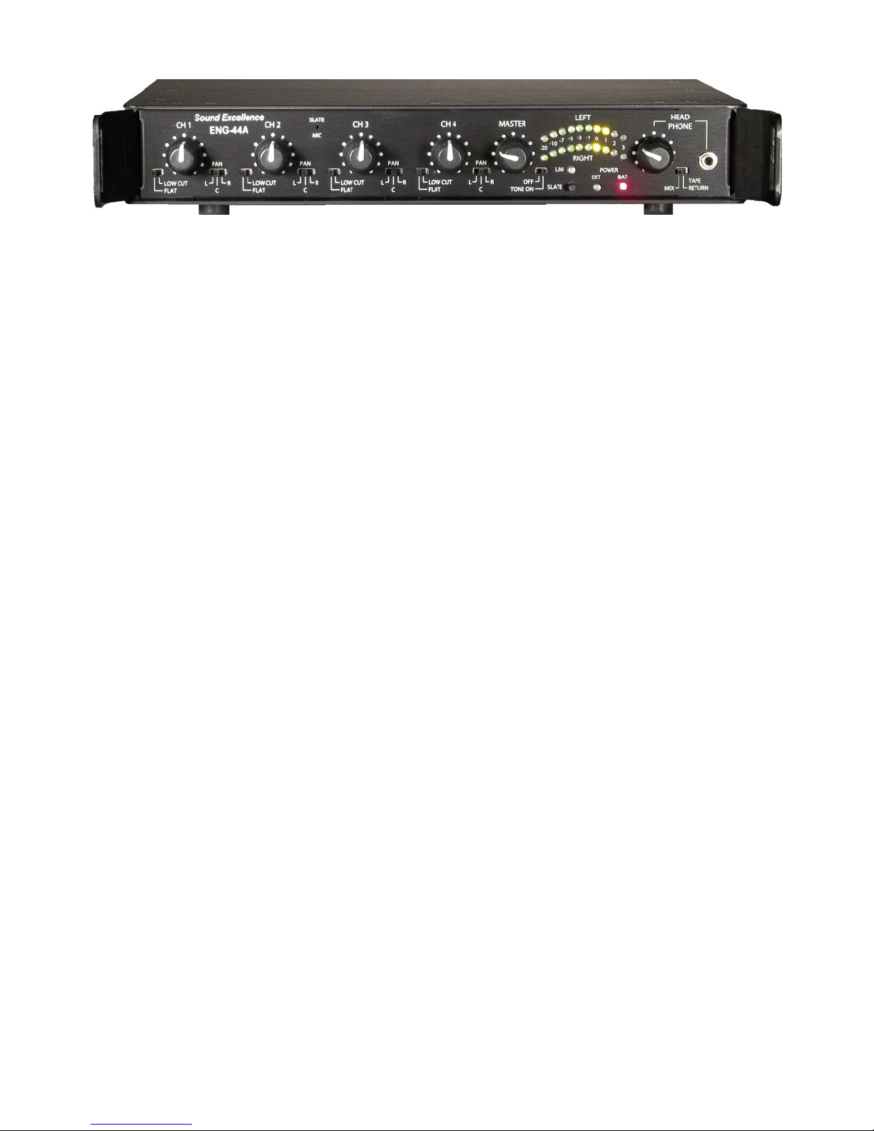
Front Panel
1. CH 1 - CH 4 Gain Controls
Individual gain controls for each of the four input audio channels,
marked 1-4. Gain controls are also known as faders or level controls .
2. Master Gain Control
Controls overall gain.
3. FLAT /Low Cut Filter Switches
Switches for each of the four input channels select between flat
(no filter) and 150 Hz roll off (attenuates audio in frequencies below 150 Hz). Use to reduce wind noise
or other low frequency noise.
4. Pan Selectors
Slide switches for each of the four input channels assign each input to either the
left, right or both audio channels. (Select C position for both channels to place the audio in the center).
5. LED Audio VU Meter
Two rows of LEDs light in progression to indicate level for both right and left
audio channels. Use VU Meter Intensity Switch on the underside of the unit to select HIGH for high
visibility outdoors or select LOW to conserve battery life.
6. Other LED Indicators
LIM Output Limiter
LIM lights when limiter is triggered by audio level beyond a specified threshold
which has been preset at the factory. The limiters compress the audio when this threshold is reached
to prevent overload. See instructions for adjusting the threshold on page 7.
Power EXT
lights automatically when external power is being used.
Power BAT
lights automatically when battery power is being used.
Low Battery Warning
BAT flashes when battery needs to be replaced. Prior to this BAT will flash on
audio peaks to offer early warning.
NOTE:
The unit is reverse voltage protected. No permanent damage can be sustained from reverse
voltage.
7. Reference Tone
Switch from MIX to TONE to generate 1KHz reference tone.
8. Slate
Momentary push button activates slate mic located on front panel. Push and hold in while
verbally identifying the audio take. Release to deactivate slate mic and continue with the take.
9. Head Phone Jack
1/8” jack for operator head phone monitoring. (Note that there is a separate
XLR head phone jack for boom operator on the right panel.) Turn down headphone level control
before connecting or putting on headphones.
10. Head Phone Level Control
Adjusts head phone volume for both mixer operator and boom mic
operator. Reduce volume before putting on headphones to protect your hearing. Use at lowest
practical level to protect your hearing.
11. Tape Return Selector
Select TAPE RETURN to monitor audio from video camera, or other
device plugged into the TAPE RTN IN on right side. Select MIX to monitor mixer output.
12. Strap Ear
Adjustable shoulder strap (included) attaches to these metal ears. These may also
protect the front panel from damage.
Page 4
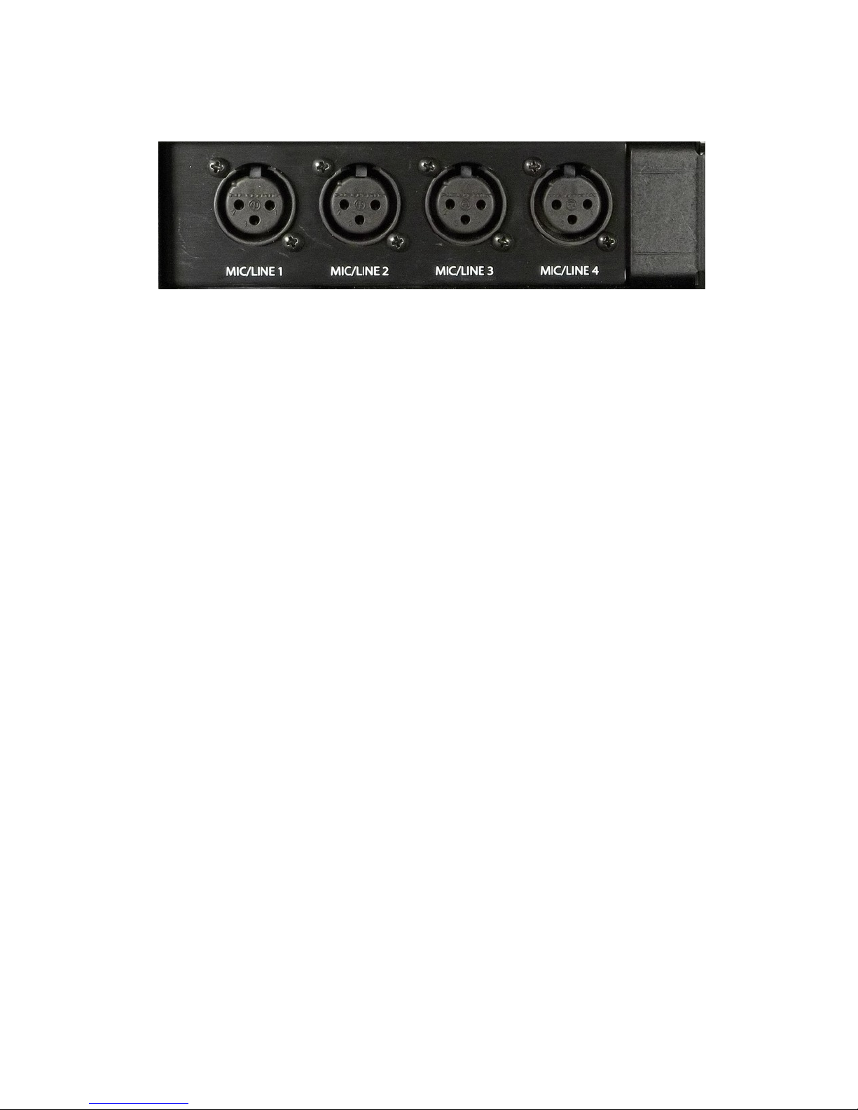
Left Panel
MIC/LINE XLR Inputs Channel 1 through 4 XLR transformer balanced audio
inputs. Use individual selector switches located on the underside panel of the unit
to choose mic/line level for each input and to activate/ deactivate +48 volt phantom
power for each input. For any given input, turn off phantom power if not specifically
required by the microphone in use (using the switch on the underside of the unit).
These XLR connectors are wired as follows:
Pin 1: Ground (shield)
Pin 2: Hot (in phase)
Pin 3: Cold (out of phase)
Phantom power for these XLR connectors is wired in the following manner:
Pin 1: Ground
Pins 2 & 3:carry 48 volts DC through 6.81K resistors when the particular
input is switched to phantom power using the corresponding switch on the
underside of the product.

Page 5
Right Panel
1. Boom Headphone Out XLR audio output for boom operator head phone monitoring. XLR
output allows use of cable with XLR connectors rather than one with ¼” connectors. Use a ¼”
adapter to connect to head phones. This way your spare XLR cable also serves as your spare
boom operator cable, and you only need carry a small spare ¼” adapter. NOTE: The single
head phone level control adjusts volume for both the boom head phone out and the front panel
head phone out.
This XLR connector is wired as follows:
Pin 1: Common ground
Pin 2: Headphone left audio
Pin 3: Headphone right audio
2. XLR Outputs Two balanced line level audio outputs. Use switch located on the underside
panel of the unit to choose between mic and line level for both. When feeding unbalanced out
from these connectors, avoid grounding a signal pin.
3. Line Out Line level 3.5 mm (1/8”) unbalanced audio output jack. Use to feed audio to
cameras that only provide a 3.5 mm audio input jack.
4. Mic Out Microphone level 3.5 mm (1/8”) unbalanced audio output jack. Use to feed audio to
cameras that only provide a mic level 3.5 mm audio input jack.
5. Auxiliary In 3.5 mm (1/8”) unbalanced audio input jack. Goes directly to internal mix bus.
6. Tape Rtn In 3.5 mm (1/8”) unbalanced audio input jack for connection to video camera,
tape recorder or other audio device for monitoring purposes only.
7. Power on/off Switch
Page 6
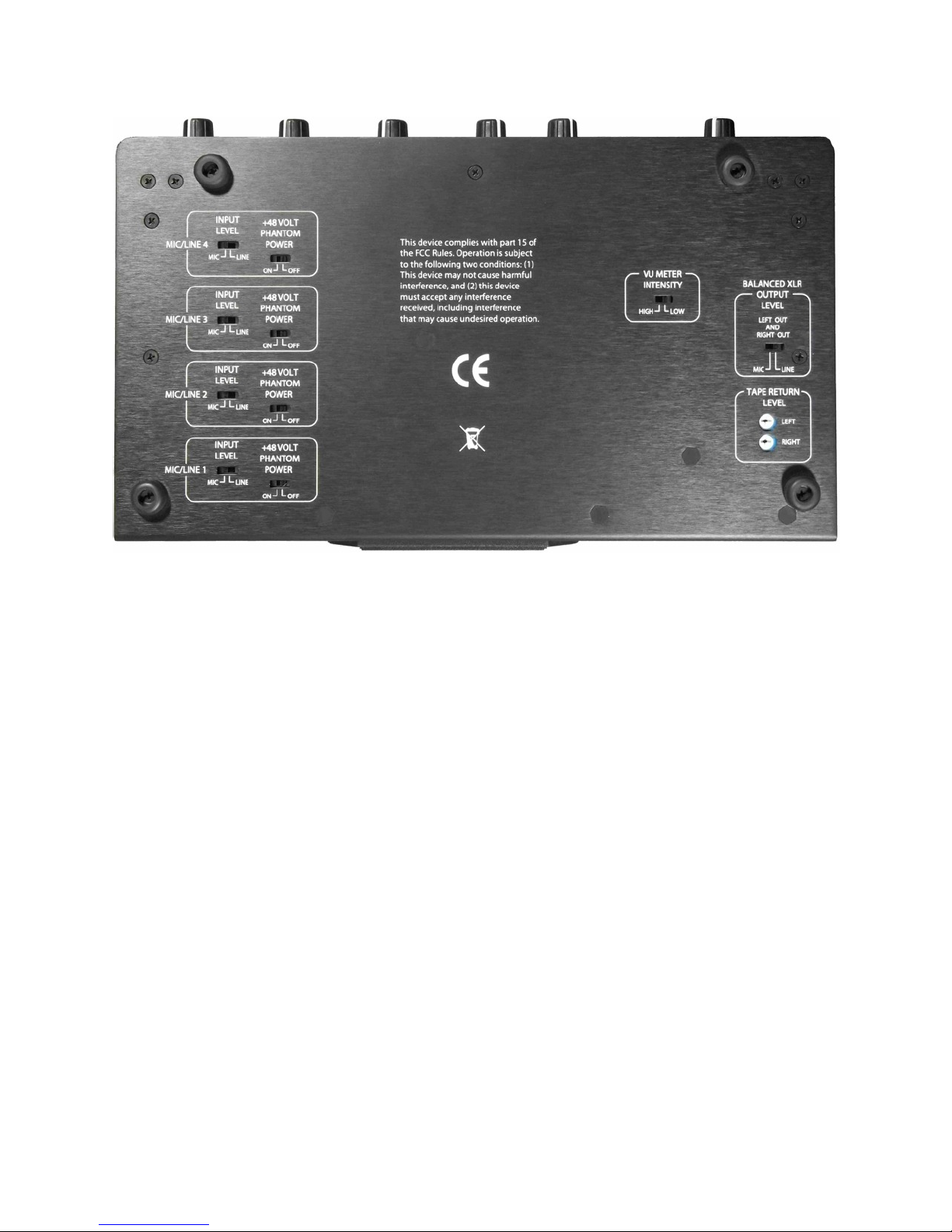
Underside Panel
1. Mic/Line Input Switches Individual switches for each input channel select between mic and
line level in.
2. Phantom Power Switches Individual switches for each input channel activate/deactivate
+48 Volt phantom power. Some microphones require phantom power to operate. However, do
not apply phantom power except for microphones that are equipped to operate on phantom
power. Check the microphone operating manual if you are not certain. For phantom power XLR
connector wiring, see Right Panel section of this manual.
3. VU Meter Intensity Switch Controls brightness of VU meter LED display located on the
front panel. Select HIGH for high visibility outdoors. Select LOW to conserve battery.
4. Tape Return Level Control Adjustable amplifiers allow matching to the vast majority of
video cameras and other recording equipment for monitoring tape confidence heads. Use a
small flat blade or phillips screwdriver to adjust the level for the best match. Many
consumer/prosumer DV camcorders may not provide tape confidence heads. However, tape
return is still valuable for checking for bad cable connections etc.
5. Mic/Line Output Switches One switch for both XLR outputs switches between mic and line
level out.
6. Feet These are supplied to protect the unit from wear for table top use. If you wish to
remove the feet, remove the feet and reinstall the existing screws.
Page 7
A
Rear Panel
1. External Power 2.1mm ID x 5.5mm OD external power jack. While this unit is designed to
operate on battery power, this input allows the unit to also be powered from a wall power outlet
by using an AC power adapter. Plug the AC power adapter itself into the wall outlet, then
connect the AC adapter’s low voltage DC output cord to this input jack. Note that power
automatically switches to external when external power is supplied, and back to battery when
external power is removed.
ŸThe ENG-44A is protected against reverse polarity.
ŸThe negative (-) side of the EXT POWER is connected to audio ground.
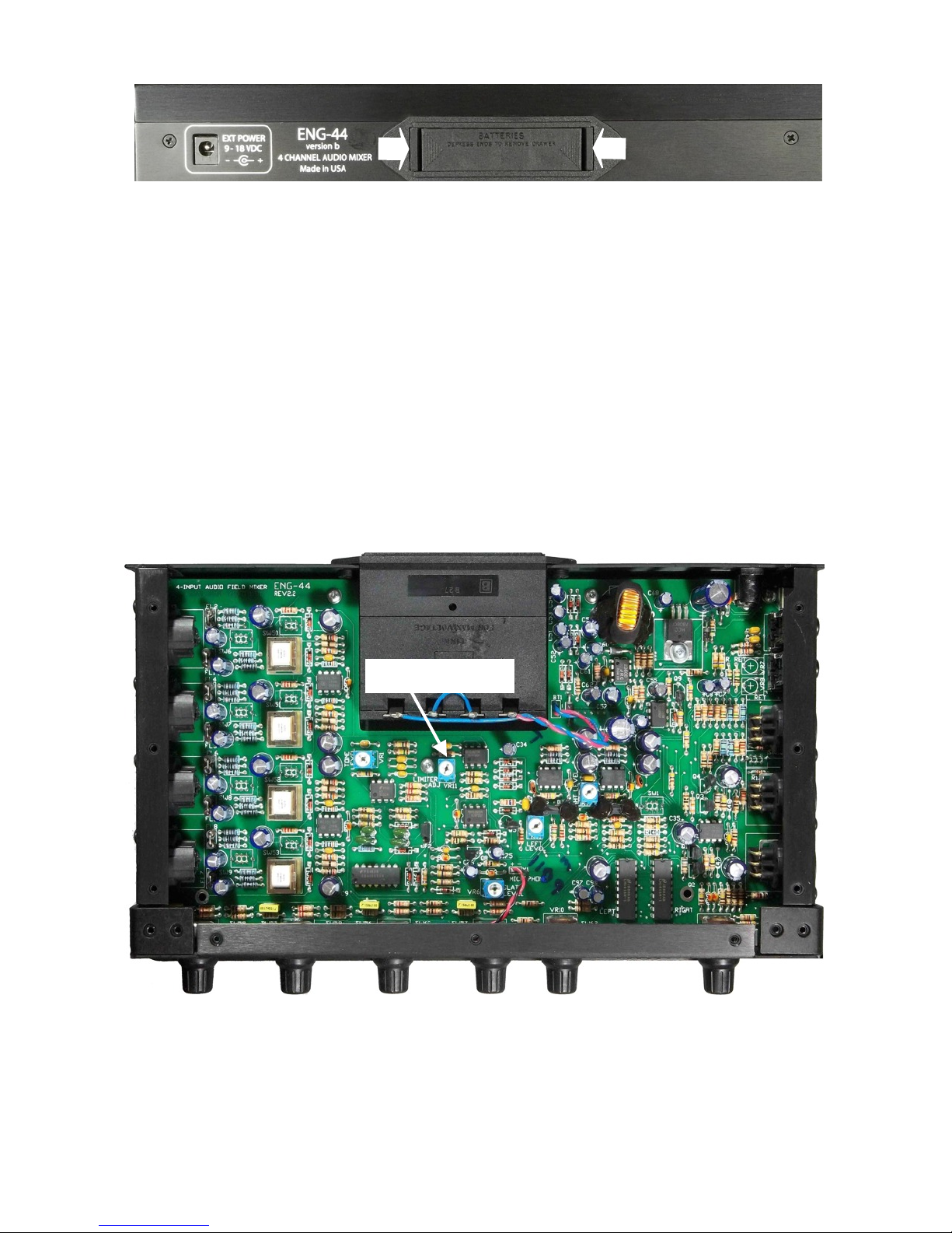
2. Battery Compartment Slide out drawer holds four AA batteries. To open drawer press inward
on outside of both tabs as shown by the arrows.
Limiter adjust
Limiter Adjust
To set the limiter:
1. Remove the top cover.
2. Turn limiter pot fully CW.
3. Apply a signal to provide an output at the desired limiter threshold.
4. Turn limiter pot CCW until the LIM LED lights moderately.
5. Wait for 30 sec for the output to stabilize, readjust as required.

Page 8 ENG-44_Opr_Man_SE3g
ENG-44A Specifications
Country of Manufacture:
USA
Input Impedance:
2K, transformer balanced
Output Impedance :
600 Ohms (both balanced and unbalanced line level outputs)
Frequency Response:
20Hz to 20kHz +/- 1.5dB
Distortion:
<.1% (1kHz @ 0dBu output)
Noise:
-126dBu EIN
Overall Gain:
66dB
0 VU Output:
0dBu (0.775 v rms)
Limiter Threshold:
+10dBu (internally adjustable)
Low Cut Filters:
-12 db at 60 Hz, -6db/octave roll off
Tone Oscillator:
1kHz
Aux Input:
Stereo 1/8" (3.5mm) jack; unbalanced line level, input
impedance of 47K Ohms, AC coupled
Tape Return:
Stereo 1/8" (3.5mm) jack; input impedance 10K, Left/Right input
levels independently adjustable
Headphone Outputs:
10 Ohms output impedance
Phantom Power:
+48VDC "48PH", individually switchable, 14mA maximum (total
of all microphones)
Internal Power:
4X "AA" batteries; Alkaline (recommended) or rechargeable
NiMH (charging unit not included)
Battery Life:
approximately 14 hours normal mixer operation
External Power:
9-18 VDC via 2.1 x 5.5mm coaxial power plug; center positive;
input protected against reversed polarity.
Cabinet Finish
Black Anodized with white lettering
Size:
1.5"x10.5"x6.5" (HxWxD), exclusive of detachable strap "ears"
Weight:
2.25 lbs (1 .0kg) with alkaline batteries (not included)
Important!
NEVER leave batteries in the mixer. They WILL corrode and
damage the battery box!
AC adapters are available at Radio Shack and by mail order from Fry’s, Amazon.com, Mouser
& Digikey. Any unit rated 9vdc with 2.1 x 5.5mm coaxial power plug; center positive will work.
Multi-voltage units with several output plugs work well.
Table of contents


