Soundavo IC-640CF User manual

OWNERS MANUAL
IC-640CF / IC-860CF
www.soundavo.com
Dear Customer, Thank you for choosing Soundavo speaker products. Take the time to read this
manual carefully before installing your speakers. It contains tips for getting the most benefit and
instructions for using them safely. We strongly recommend that you keep the packaging and this
manual for future use.

SAFETY WARNINGS AND GUIDELINES
2
• These speakers are intended for indoor use
only.
• Do not expose these speakers to water or
moisture of any kind.
• If operating these speakers in a humid
environment, ensure that no condensation
occurs. Condensation could cause damage to
the speaker cones and voice coils.
• Power off and unplug all Audio/Video compo-
nents when making wired connections. Only
apply power after all connections have been
made.
• Double-check all connections prior to applying
power to ensure that speaker polarity is
properly made and that there are no stray wire
strands, which could short the connections,
either on the backs of the speakers or the AV
receiver/amplifier.
• Do not use full volume until after the speakers
have been fully broken-in.
• If you hear distortion, reduce the volume until
the distortion is no longer audible. Distortion
can sound like a buzzing, scratching, or
hammering sound. Distortion can damage to or
destroy the delicate speaker coils.
• Do not use cleaning fluids, solvents, or other
chemicals to clean the speaker frames or
grilles.
• Do not use excessive volume when listening to
these speakers. If you experience pain,
discomfort, or dizziness, reduce volume
immediately. Prolonged exposure to excessive
volume can cause permanent hearing damage.
• Do not disassemble or attempt to service these
speakers.
• You must use speaker wire rated for in-wall
use.
• Do not attempt to install these speakers near
power outlets, wall switches, or ceiling fixtures.
These objects indicate the presence of AC
power lines within the wall or ceiling and
should be avoided.
• When checking for the presence of objects
behind the wall, do not try to force the wire
past obstructions.
• Always check and adhere to your local building
and fire safety codes before installing these
speakers and running wires through the walls
and ceiling.

3
INTRODUCTION
Thank you for purchasing Soundavo Premium
In-Wall/In-Ceiling Speakers!
Our In-ceiling speakers are special designed
and fine tuned by Soundavo engineering team,
provide the excellent sound quality and styling
for your best listening experience. This range
of speaker are designed for the stereo music
playback, multi-channel audio, home theater
surround, or any primary listening application.
Rather than cluttering the room with large box
speakers trailing speaker wires, the speakers
are virtually invisible, while filling the room with
high fidelity audio. Featuring removable and
paintable grilles, these speakers use carbon
fiber woofers for superior bass and mid-range
reproduction and ribbon (in-wall models only)
or air-motion (in-ceiling models only) tweeters
for sweeter and cleaner highs.
In-Wall and In-Ceiling speakers are identical in
concept and differ only in their form. Wall
speakers are traditionally square, like windows
and doors, while ceiling speakers are tradition-
ally round, like light fixtures. The instructions in
this manual specify installation into a wall, but
the same procedures apply to ceiling installa-
tions.
IN-WALL VERSUS IN-CEILING SPEAKERS

4
SPEAKER WIRE PREPARATION
Before attempting to make any connections it
is best to look at the situation, get all the
necessary materials together, and then make
all the connections at once.
First, look at the back of your amplifier or
receiver to determine what options it offers for
making connections. Amplifiers and receivers
typically employ either 5-way binding posts,
spring-loaded terminals, or push terminals for
the speaker connections.
A 5-way binding post can accept bare speaker
wire, spade plugs, pin plugs, and banana
plugs, while spring loaded terminals and push
terminals can accept either bare speaker wire
or pin plugs. Refer to the documentation that
came with your amplifier or receiver to
determine the maximum size/gauge speaker
wire the speaker terminals can accept.
The in-ceiling speakers feature push terminals,
which can accept pin plugs or bare wire up to
14AWG. The in-wall speakers feature blade
connectors. You should use .250" 16-14AWG
crimp style blue female disconnects (not
included) on the speaker end of the speaker
wire.
If your amplifier can accept it, you should use
14AWG speaker wire. Using pin plugs is highly
recommended for several reasons. Plugs are
easier to connect, don't run the risk of stray
wire strands shorting the connections, allow for
use of heavier gauge speaker wire in most
cases, and it is much easier to identify the
polarity from a color coded ring on a plug then
from a subtle marking along the length of a
wire.
Because the speaker wires will necessarily be
run through your walls, you must use in-wall
rated wire. This is required by fire safety codes
and ensures that the wire jacket will not act as
an accelerant in the event of a fire.
Rather than using fixed length speaker wires, it
is best to get a roll and cut the wires to the
length you will need them. This ensures that
there is a minimum amount of excess wire.
However, even if your amplifier is off-center,
the lengths of wire used for each speaker pair
should be identical. This keeps the impedance
on each channel the same, which ensures that
the volume levels, frequency ranges, and
tonalities are identical. Any excess wire should
be snaked back and forth, not coiled, to avoid
creating an inductor/antenna for stray radio
signals.
Before making the actual connections, cut
each length of wire to size. Note the markings
on the wire that differentiate between each
conductor. Sometimes the marking clearly
identifies a positive and negative side. Some
common clearly positive and negative
markings or identifiers are:
In many cases, the mark is a single stripe on
the jacket of one of the connectors. In this case
the side with the stripe is generally considered
the positive side, but it really does not matter
as long as you are consistent and always using
the stripe as positive or always using it as
negative.
When you are ready to prepare your speaker
wires, first separate about 4" of wire, then strip
about 1/4" (6mm) insulation from the end and
twist it to prevent stray strands. If you plan to
use banana or pin plugs (highly recommend-
ed), install the plugs on the wire.

5
POSITIONING THE SPEAKERS
For the Stereo Speakers setup, should be approximately 6 to 10 feet (100 to 300 cm) apart. If
possible, the left and right speakers should be located the same distance from the listening position.
For the Home Theater setup, the In-ceiling speakers can be used as surround speakers. When
installing the speakers in the ceiling, place them from 3 to 6 feet (90 to 100 cm) behind the listening
position, and space the speakers from 6 to 10 feet (100 to 300 cm) apart.
In-Ceiling Placement - Stereo
In-Ceiling Placement - Home Theater
TV

INSTALLATION
Preparing the surfaces / finishes of walls and ceilings Before installing the speakers, it is necessary to
install the cables in the intended location. Contact your dealer for more information on cable installa-
tion. Once the cable is properly installed, you are ready to install your speakers.
The location chosen should be free of obstacles such as electrical conduits, air conditioning ducts, or
water pipes. Access to an attic or crawl space can help you locate their location.
Mounting surface preparations / Finished ceilings and walls
1. Determine the best location for mount your speakers
Make sure there are no nails and other parts around the location of your speakers. If you place the
speakers near other devices, be sure to check the size of the brackets, which extend beyond the
mounting cutout.
2. Find the studs / joists nearest the desired speaker mounting location
A punch out template for setting the hole is provided in the box. Position the template in the desired
position and pencil an outline on the wall or ceiling.
3. Make the hole
6
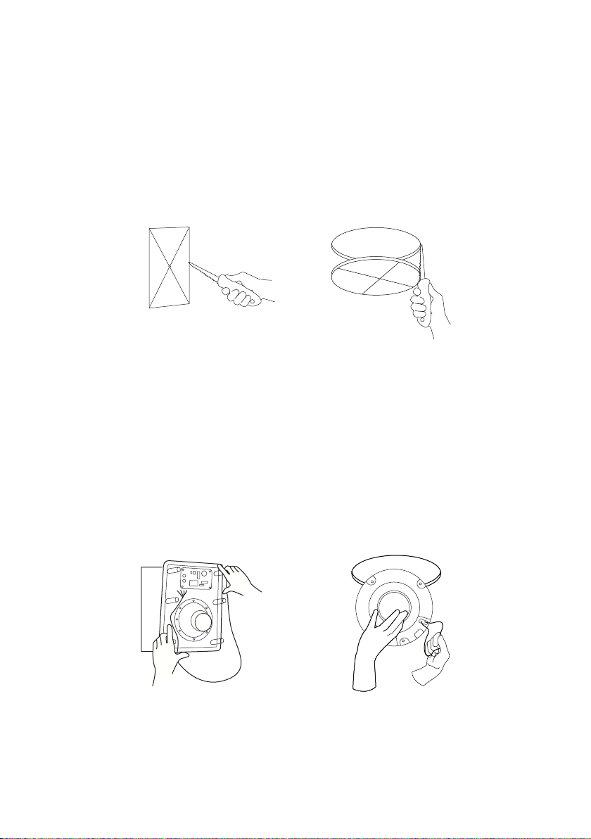
Caution : this is the most important part of the entire installation. If you are uncertain about obstruc-
tions in the mounting area, you should start by cutting a small hole within the penciled area with a
drywall saw. Cutting at a 45 degree angle will make drywall repair much easier should you need to
patch the hole due to obstructions. Once you have determined there are no obstructions in your
desired mounting location, start cutting the finished hole at a 90 degree angle to the wall surface. This
step is the most important step in the entire installation. If you are not sure of the obstacles in the
cutting area, start by cutting a small hole in the cutting area with a drywall saw. If obstacles are
present, cutting at a 45 degree angle will make repair much easier. Once you have made sure there
are no obstacles in the chosen location, cut the wall or ceiling at an angle of 90 degrees to the
surface.
If the area in the ceiling or wall is not already insulated, add an adequate amount of insulation material
to fill the cavity. If the insulation material used is faced with foil or paper, position the foil or paper
away from the speaker.
The integral mounting-feet system incorporated into your speaker allows for a quick installation by
following these easy steps.
1. Remove the grid and set aside in a clean dust-free environment.
2. Attach the speaker cable (observing the proper polarity with your amplifier : + to +, - to -). Make
sure the left channel of the amplifier channel is connected to the left speaker channel and the right
amplifier channel to the right speaker channel.
4. Cutting the hole
5. Add insulation
7
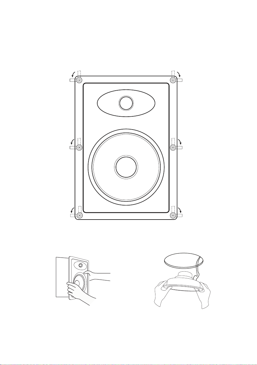
3. Make sure the mounting feet are turned inward to clear the opening and insert the speaker into the
ceiling or wall. Position the speaker into the hole.
8

Note : The flange of the speaker is designed to flex and conform to any small imperfections in the wall
surface. Tighten the 6 screws on the front of the baffle only enough to make the flange become snug
against the ceiling or wall. As you tighten the screws, the feet will automatically flip into an outward
position, thereby clamping the drywall between the feet and the flange.
Caution : Over-tightening may warp the baffle, crack the wall, cause the flange to distort, and make
the grid difficult to install.
Note : The speaker flange incorporates high strength magnets to secure the grid into place. Simply
line the grid with the speaker flange.
4. Secure the grid into place.
9
PAINTING INSTRUCTIONS
The grids can be painted to match your walls, making the speaker even less noticeable. However,
great care should be taken not to clog the holes, as this will greatly reduce the sound quality of the
speakers.
If you plan on paint your grids, we recommend that it be done prior to installation. The scrim cloth
backing must be removed prior to painting the grids. The surface should be cleaned with a light
solvent to remove any dust or residue. Soundavo recommends a light spray-painting using 5 parts
thinning agent to 1 part paint. Do not paint the grid while they are attached to the speaker, before
proceeding with installation. Ensure that the holes in the grille are not blocked by paint.
• Remove the center portion of the cardboard
installation template/paint mask. The central
portion is the paint mask, while the outer
portion is the installation template.
• Completely remove the grille by inserting a
paper clip or the included grille removal tool
into one of the holes and pulling to lift it off
the frame.
• Remove the foam insert and set it aside.
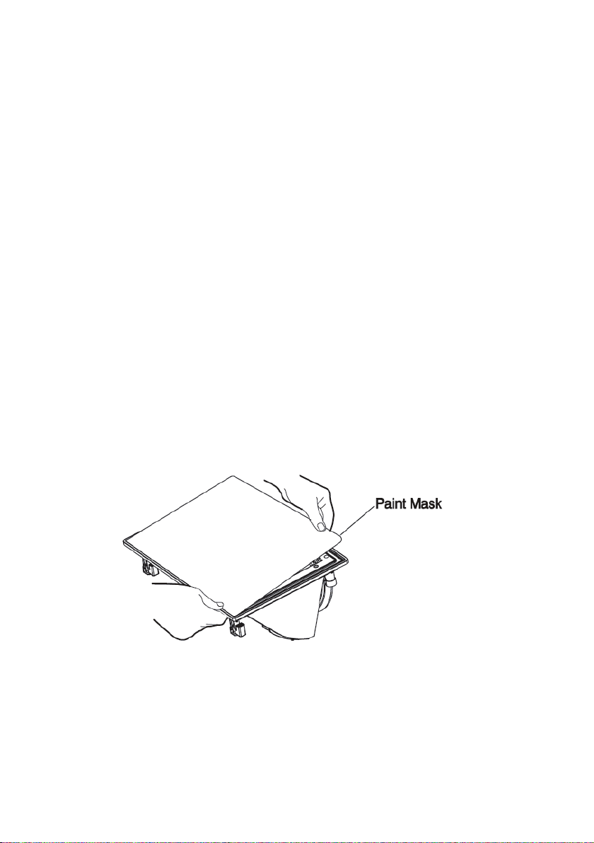
Perform the following steps to safely paint them without damaging the speaker.
• Insert the paint mask, covering the speaker
while leaving the frame exposed.
• Paint the speaker frame and grille. It is best to
use spray paint to avoid paint clogging the
holes in the grille.
• Allow the paint to completely dry
10

PRODUCT SPECIFICATIONS
Power Handling: 40W RMS / 80W Peak
Tweeter: 3/4” Alu. Dome
Woofer: 6” Carbon Fiber With Rubber Edge
Frequency Response: 50Hz - 20KHz
Impedance: 8 Ohms Nominal / 6 Ohms Minimum
Sensitivity: 88 dB
Crossover: Hi-12dB / Lo-12dB
Terminal: Gold-Plated Push-Type Terminal
IC-640CF
Power Handling: 60W RMS / 120W Peak
Tweeter: 1” Alu. Dome
Woofer: 8” Carbon Fiber With Rubber Edge
Frequency Response: 40Hz - 20KHz
Impedance: 8 Ohms Nominal / 6 Ohms Minimum
Sensitivity: 89 dB
Crossover: Hi-18dB / Lo-18dB
Terminal: Gold-Plated Push-Type Terminal
IC-860CF
11
PRODUCT SPECIFICATIONS
The packaging (cartons and foams) has been
designed to effectively protect your SOUNDA-
VO electronics during transport and shipping.
We invite you to keep them for future use.
Protect the environment: if you want to get rid
of the packaging, note that it is recyclable. We
invite you to make the arrangements for the
best respect of the environment according to
the possibilities which are offered to you
(sorting for example). At the end of his life, this
device should not be thrown into a convention-
al trash bin. It must be returned to a recycling
center for electronic equipment. This symbol
on the product indicates that it is designed to
be recycled according to a particular process.
You will make a very significant contribution to
the preservation of the environment. This
device complies with the RoHS European
directive. This means that it does not release
polluting substances during recycling (Lead,
Mercury, Cadmium, Hexavalent Chromium,
Polybrominated biphenyls, Polybrominated
diphenyl ethers).
Precautions for proper use
This product was designed according to
rigorous norms and complies with safety
standards. It should only be used under normal
conditions as described below. Verify the
electrical voltage before connecting it to a
power source. This electronic device was
designed to work in numerous countries. We
advise you to hook it up completely before
connecting it to the AC power source. Take
care when unplugging the power cord. When
you unplug the power cord from the power
source, do so by pulling on the head of the
plug rather than on the cable. If you do not
expect to use this device for a prolonged
period of time, you are advised to unplug it
from the power source. Do not open the case.
This device contains no parts that can be
exchanged by the user. Accessing the inside of
this device’s case can lead to electric shock.
Any modification to the product will nullify the
guarantee. If a foreign object or liquid falls into
the case, contact your retailer to arrange for a
technician to remove it from the device safely.
Soundavo platinum is designed and manufac-
tured to the highest quality standards. If there
is a defect in your Soundavo product,
Soundavo customer service or an authorized
dealer may take care of the repair within the
limits of this warranty.
The warranty is 2 years from the date of
purchase from an authorized dealer.
Definition of Warranty The warranty is limited
to the repair of Soundavo equipment. Under no
circumstances is the transport, the associated
costs and the installation covered by the
guarantee.
The warranty is only applicable to the first
owner and is not transferable.
The guarantee does not apply in the following
cases:
- The damage is caused by incorrect installa-
tion or connection.
- The damage is caused by improper use,
other than that described in this manual, by
negligence, or modification of the product by a
person not authorized by Soundavo.
- Damage caused by accidents, lightning,
water, fire, excessive heat or any other cause
that can not be controlled by Soundavo.
- In the case of repair by unauthorized
personnel. This warranty supplements the
legal warranties in force in the country of the
authorized dealer.
How to repair a product under warranty Simply
contact your authorized dealer. To ensure
transport in good conditions, always use the
original packaging. If you use a product in a
country other than where you bought it, contact
the importer in your country of residence who
will refer you to an authorized service center.
The list of authorized distributors is available on the website:
http://www.soundavo.com To validate your warranty, you must produce as proof of purchase the
original of your invoice containing the date of your purchase and the stamp of your dealer.
WARNING WARRANTY
12
This manual suits for next models
1
Table of contents
Other Soundavo Speakers manuals


