SoundMax SM-SA604 User manual

SOUNDMAX SM-SA604
SM-SA604
4-CHANNEL CAR AMPLIFIER 4-КАНАЛЬНЫЙ УСИЛИТЕЛЬ МОЩНОСТИ
Instruction manual Руководство по эксплуатации

SOUNDMAX SM-SA604
2
YOUR NEW HIGH FIDELITY BRIDGEABLE/STEREO AMPLIFIER IS DESIGNED TO DELIVER MAXIMUM
ENJOYMENT AND ONE YEAR OF TROUBLE FREE SERVICE.
TABLE OF CONTENTS
TABLE OF CONTENTS ........................................................................................................................ 2
FEATURES ....................................................................................................................................... 3
PRECAUTIONS.................................................................................................................................. 3
INSTALLATION ................................................................................................................................. 5
CONNECTIONS ................................................................................................................................. 6
OPERATION ELEMENTS AND IN / OUTPUTS .......................................................................................... 7
FIG. 1 POWER SUPPLY/REMOTE TURN-ON CONNECTION .................................................................... 8
FIG. 2 4-CHANNEL MODE............................................................................................................... 9
FIG. 3,4 3-CHANNEL MODE ............................................................................................................. 10
FIG. 5 2-CHANNEL MODE............................................................................................................. 12
FIG. 6 USE THE AMPLIFIER TO DRIVE FOUR SATELLITE LOUDSPEAKERS AND
A SUBWOOFER WITH USING AN ADDITIONAL 2-CHANNEL AMPLIFIER................................................... 13
FIG. 7 OPERATING ELEMENTS AND IN/OUTPUTS................................................................................. 14
TROUBLE SHOOTING GUIDE ............................................................................................................ 15
SPECIFICATION.............................................................................................................................. 16

SOUNDMAX SM-SA604
3
Features
• Class ''AB'' Technology MOSFET PWM Power Supply
• Remote turn-on of the amplifier via car radio
• Continuously Variable 12dB/Octave High Pass & 12dB/Octave Low Pass Crossover
• Enhanced Bass Boost 0/12dB @50Hz
• Regulator for input sensitivity
• Bridgeable 4-/3-/2-/1-channel & Tri-mode
• Silver Plated RCA & Power, Speaker Terminal
• Soft Start & Muting
• Capsulated screw terminals of loudspeaker and power supply
• Overload, Thermal, Short Circuit Protection
• Power & Protection indicator
Precautions: Read First!
• If after reading the direction you feel uncomfortable about installing the amplifier in your car, or not equipped
or competent to do so, you should have the amplifier installed by an authorized installer. It's your car!
• Negative battery terminal must be disconnected before any electrical connections are made.
• Be sure choose a location that provides substantial ventilation for the amplifier.
• The most preferred locations would be in your car's trunk, under the front seats or on the back wall of a
truck.
• The location chosen should provide at least 2" of clearance above the amplifier for adequate ventilation.
• If the amplifier is to be mounted vertically be sure that it is in a place where adequate air will flow along the
length of its heatsink fins for cooling.
• NEVER mount the amplifier up side down, this will cause the heat to rise back into the amplifier causing
thermal shutdown or possible permanent damage.
• NEVER mount the amplifier in a location that is subject to direct sunlight or exposed to moisture.
• Be sure to mount the amplifier to a strong, solid surface which will not give way under the stress of a sudden
stop.
• Make sure that the mounting screws will not penetrate the gas tank, brake and fuel lines, wiring or other
critical parts of your car when installed.
• NEVER operate the amplifier without the proper power and ground wire 10 gauge minimum.

SOUNDMAX SM-SA604
4
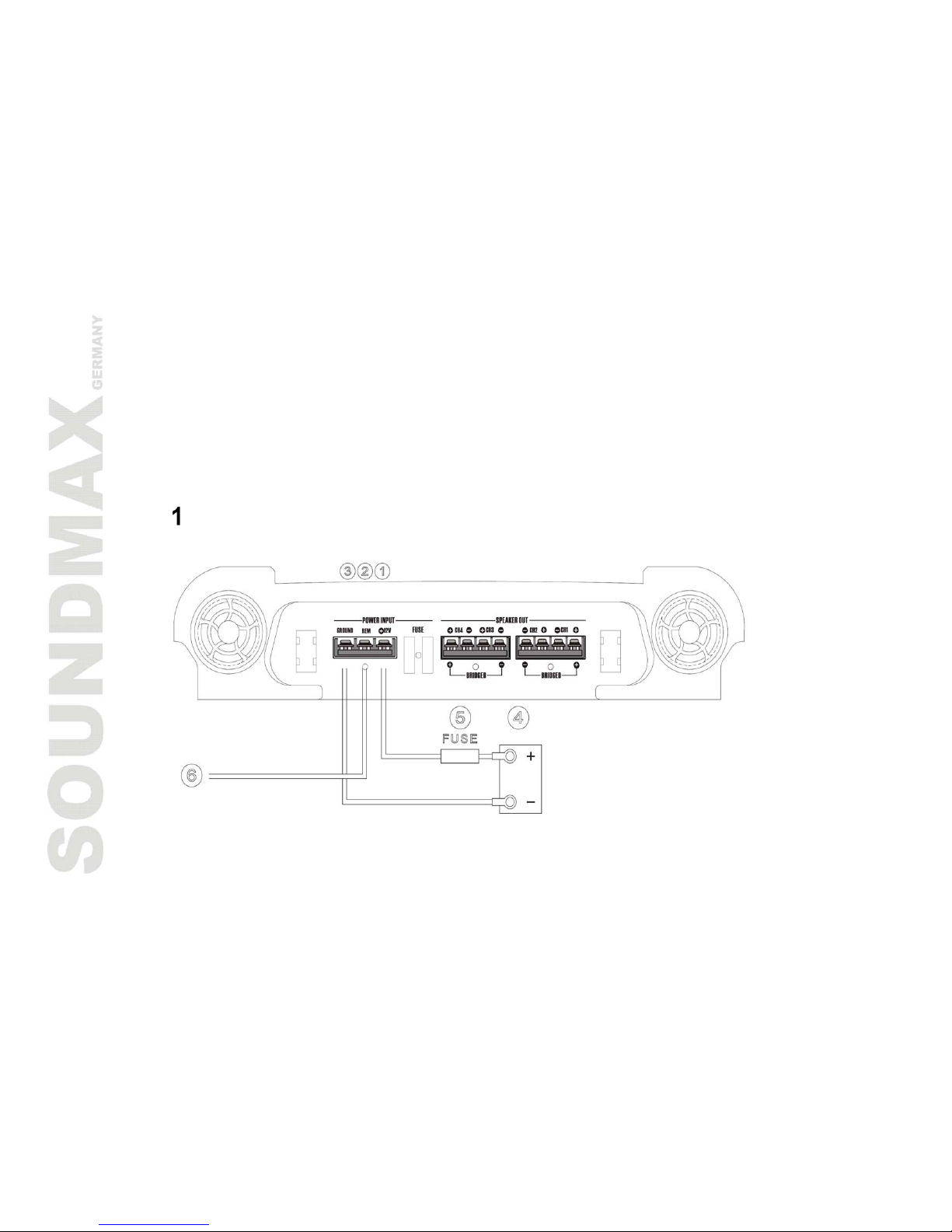
• NEVER operate the amplifier without proper fusing. Fuse holder must be located with in 0.5 meters from the
battery. This fuse is to protect the car not the electronics. In case of a short, the fuse will blow instead of the wire
burning up. Using other than the recommended fuse ratings at the battery and at the amplifier may cause damage
to the amplifier and will void your warranty.
• Do not run wiring underneath or outside the car since exposure to the elements may cause the insulation to
deteriorate rapidly, resulting in short-circuits and/or intermittent operation. All cables should be run beneath
carpets and inside trim pieces.
• To help minimize interference, it is best to run the power cables along the opposite side from the audio cables.
• Whenever wires pass through metal, rubber or plastic grommets must be used to prevent the mental from
wearing through the installation and causing a short.
• Whenever possible, use cable ties, mounting clamps and similar wiring aids (available from an electrical supply
or auto parts store) Adding stress relief loops to wiring is also advisable to prevent straining or breakage.
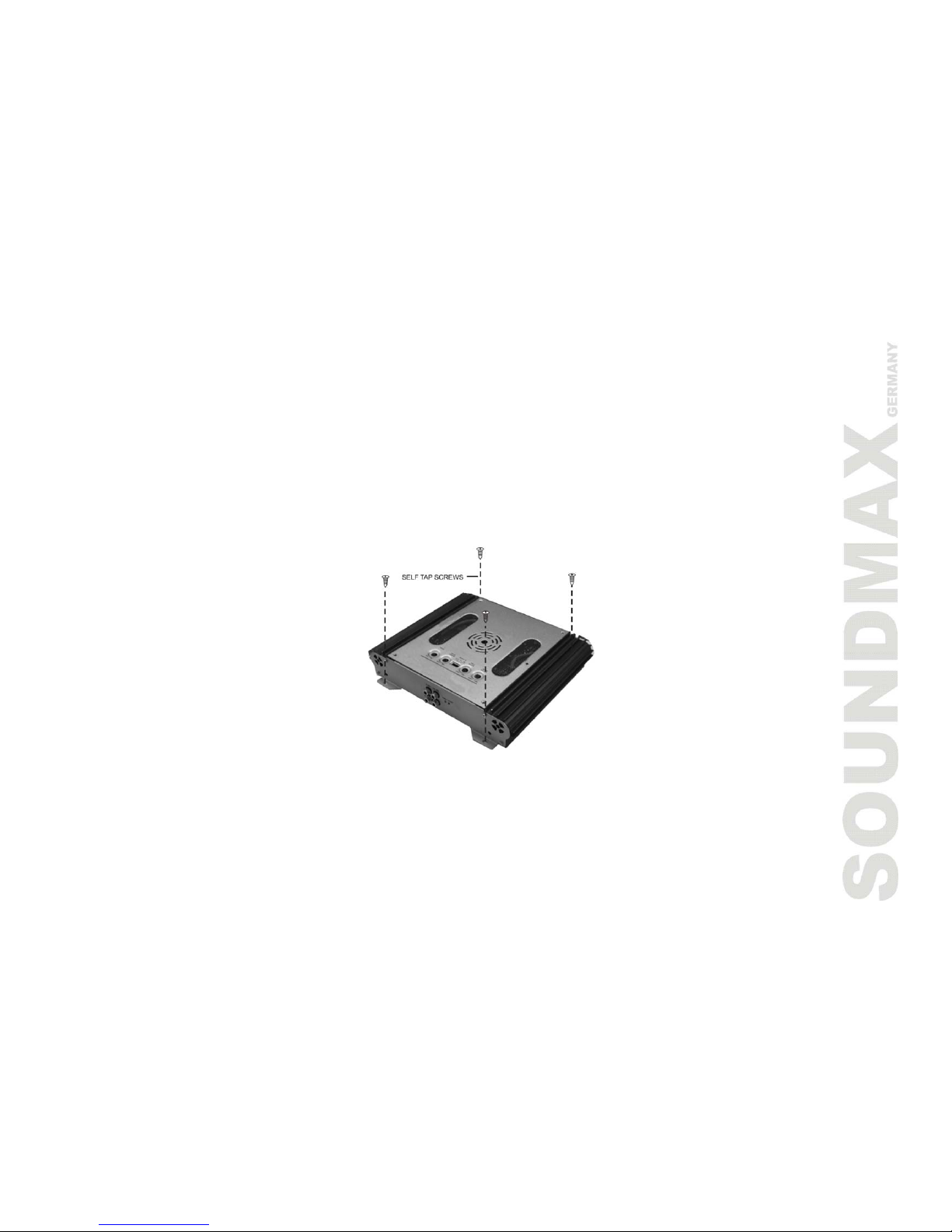
• It is best to test the system before the amplifier is mounted and interior of car is reassembled.
• If the temperature inside your car reaches extreme levels (such as sitting locked up for several hours in the hot
sun or exposed to a very cold winter's day) the amplifier may go into protection mode and shut off. Leave the unit
off until the ambient temperature returns to normal.
• The amplifier operates with any vehicle using a 12 volt negative ground system.
• NEVER ground the speaker leads and NEVER allow the speaker leads to come in contact with each other.
Speaker wire should be 18 gauge or larger.
• Remote turn on wire must be switched by the radio does not have a remote turn on or antenna output, connect
to wire that has a positive 12 volts when the key is turned to the accessory. If the amplifier does not turn off the
battery will die.
• Do not listen to high volumes for extended periods of time or hearing damage may occur.
• The specifications of this device can be changed by supplier without any notification
• The pictures have been done for reference and can be different from real units.
CONTINOUS EXPOSURE TO SOUND PRESSURE LEVELS OVER 100dB
MAY CAUSE PERMANENT HEARING LOSS. HIGH POWERED
AUTOSOUND
SYSTEM MAY PRODUCE SOUND PRESSURE LEVELS WELL OVER
130dB. USE COMMON SENSE AND PRACTICE SAFE SOUND.

SOUNDMAX SM-SA604
5
Installation
MOUNTING:
1. After reading precaution, decide where you are going to install the unit. Also, see Fig.1.
2. Once the location has been determined, remove the plastic decorative panels from left and right sides of
amplifier then place the amplifier in position. Using a felt tip pen or pencil mark the four holes to be drilled for
mounting. NEVER use the amplifier as a template for drilling. It is very easy to damage the amplifier surface in
manner.
3. Remove amplifier with a getting back the plastic panels. Drill four 3.5 mm. Diameter holes into mounting
surface on steel panel. If you want mounting the MDF or wood panel, drill four 3.0m/m diameter holes into
mounting surface.
4. Mount the amplifier using the supplied 4 self-threading screws.
INSTALLATION DIAGRAM
Fig.1

SOUNDMAX SM-SA604
6
Connections
POWER SUPPLY AND REMOTE TURN-ON OF THE AMPLIFIER
NOTE: Do not connect the plus terminals to the car battery before other connections, or it may occur short
circuit.
The gauges of power and ground cables should be enough for the amplifier demands at least 5.27mm2.
Firstly connect the GROUND terminal to the battery negative pole. It is very important that the connection is
fastened. Loose connection may cause malfunctions or interference noise or distortion. Dirt residues must be
carefully removed from the battery connection point.
Then connect the +12V DC power terminal via an integrated fuse to the battery plus pole. The fuse must be
located close to the battery, the length of cable from the battery positive pole to the fuse must be 50cm for safety.
Install the fuse after other connections including the connection of the stereo and the loudspeakers.
Finally connect the terminal of the remote turn-on to the amplifier REM control jack. The cable gauge of
0.75mm2is sufficient for the amplifier REMOTE connection.
AUDIO CABLES
When installing the stereo input connection and the speaker connection, make sure the audio and the power
supply cables do not run the same side of the vehicle.
This reduces crosstalk interference to the audio cables.
LOUDSPEAKER CONNECTIONS
• In normal operation mode (I. e. one loudspeaker on each Individual amplifier channel), the lowest terminal
resistance is 2 Ohms per channel.
• In bridge mode (two amplifier outputs combined), the lowest terminal resistance is 4 Ohms.
• The impedance in tri-mode must be not below than 2 Ohms per channel.
• Never connect the loudspeaker negative terminals to the vehicle chassis.
• Do not connect the +12V power supply to a loudspeaker output otherwise this will destroy the amplifier
terminals.
NOTE: If the amplifier is operated with lower terminal resistance or incorrectly application as described above,
both the amplifier and the loudspeakers may be damaged. The warranty becomes void in such cases.

SOUNDMAX SM-SA604
7
Operation elements and in / outputs
SETTING THE INPUT AND SENSITIVITY
The regulator for input sensitivity is used to adapt amplifier for each car radio or tape deck. Turn the
volume control of your radio to central position and adjust the input-level control (3) and (4) Fig. 7, to
produce a medium volume.
This setting can provide sufficient power and optimum Signal to Noise (S/N) ratio.
CAUTION: Do not run the amplifier in high volume for long time, otherwise the loudspeakers will be
damaged.
LOW-PASS FILTER WITH ADJUSTABLE CROSS-OVER FREQUENCY
If the unit is used as a subwoofer amplifier, turn the switch (9)/(10) to "LP". And set proper cross-over
frequency with adjusting the control (7)/(8) to make the filter match the timbre requirement of the
installed woofer.
The crossover slope of the filter can accurately reduce the medium and high frequency ranges.
HIGH-PASS FILTER WITH ADJUSTABLE CROSSOVER FREQUENCY
If the amplifier is used for satellite loudspeakers (mid-range/tweeter loudspeakers), turn switch (9)/(10)
to "HP". Set proper crossover frequency with adjusting the control (11)/(12). The frequencies only above
the setting will be amplified. This can effectively minimize distortions caused by excessive membrane
movement at the low frequencies. And the result does not reduce the bass level when it is used for small
power-supply loudspeakers.
BASS-BOOST
Use the bass-boost function (5/6) to eliminate harmonic distortion of the lower bass frequencies and
weaken the bass faction.
OUTPUTS FOR CONNECTING ADDITIONAL AMPLIFIERS
The input signals of the INPUT connections CH1/CH2 (1) are directly output to the OUTPUT (13) jacks.
Additional amplifiers can be connected to the LINE OUT jacks without additional T-plugs and cables.

SOUNDMAX SM-SA604
8
Fig.1 Power supply/remote turn-on connection
(1) Terminal for +12V battery voltage
(2) REM terminal for remote turn-on
(3) GND terminal for the ground, to the battery negative pole
(4) Battery
(5) Cable fuse
(6) To automatic antenna connection in your car radio
If your car is not equipped with an automatic antenna connection, connect this cable plus pole (+)
to the ignition lock. An on/off switch should be inserted in this case. Make sure that this switch is
turned off if the amplifier is not used.
Fig. 1

SOUNDMAX SM-SA604
9
Fig.2 4-channel mode
Connect and set the amplifier as shown in Fig. 2, when the stereo has four outputs and the unit
is used to drive four loudspeakers.
(1) To the car radio, front left output (5) Front left loudspeaker
(2) To the car radio, front right output (6) Front right loudspeaker
(3) To the car radio, rear left output (7) Rear left loudspeaker
(4) To the car radio, rear right output (8) Rear right loudspeaker
Fig. 2

SOUNDMAX SM-SA604
10
Fig. 3/4 3- channel mode
In the 3-channel mode, use high pass filter to regulate channels 1/2 and use low pass filter to regulate
channels 3/4. Chapter Operation elements and in / outputs describes how to set the filters.
FIG. 3
Connect and set the amplifier as shown in Fig. 3 if the stereo has two outputs and the unit is used
to drive two stereo satellite loudspeakers and a subwoofer
(1) To the car radio, left output (4) Right satellite loudspeaker
(2) To the car radio, right output (5) Subwoofer
(3) Left satellite loudspeaker
Fig. 3

SOUNDMAX SM-SA604
11
FIG. 4
Connect and set the amplifier as shown in Fig. 4 if the system has two stereo outputs and one car
radio output and is used to drive two stereo satellite loudspeakers and a subwoofer.
(1) To the car radio, left output (4) Left satellite loudspeaker
(2) To the car radio, right output (5) Right satellite loudspeaker
(3) To the car radio, subwoofer output (6) Subwoofer
Fig. 4

SOUNDMAX SM-SA604
12
Fig. 5 2- channel mode
If the amplifier needs high power output to drive two subwoofers, connect and set it as shown in Fig. 5.
The usage of the low-pass filter is described in Operation elements and in / outputs chapter
(1) To the car radio, left output (3) Subwoofer
(2) To the car radio, right output (4) Subwoofer
Fig. 5

SOUNDMAX SM-SA604
13
Fig. 6 Use the amplifier to drive four satellite
loudspeakers and a subwoofer with using an
additional 2-channel amplifier
(1) To the car radio, front left output
(2) To the car radio, front right output
(3) To the car radio, rear left output
(4) To the car radio, rear right output
(5) Front left loudspeaker
(6) Front right loudspeaker
(7) Rear left loudspeaker
(8) Rear right loudspeaker
(9) Subwoofer
Fig. 6

SOUNDMAX SM-SA604
14
Fig.7 Operating elements and in/outputs
(1) Low-level inputs (channel 1 /2, front)
(2) Low-level inputs (channel 3 /4, rear)
(3) Input-level control channel 1 /2
(4) Input-level control channel 3 /4
(5) Bass-boost control (channel 1 /2, front)
(6) Bass-boost control (channel 3 /4, rear)
(7) Cross-over control for the low pass (channel 1 /2)
(8) Cross-over control for the low pass (channel 3 /4)
(9) HPF (high pass filter)/LPF (low pass filter)/OFF
option switch for channel 1 /2
(10) HPF (high pass filter)/LPF (low pass filter)/OFF
option switch for channel 3 /4
(11) Cross-over frequency for control for the high pass
(channel 1 /2)
(12) Cross-over frequency for control for the high pass
(channel 3 /4)
(13) Low level outputs (channel 1 /2)
Fig. 7

SOUNDMAX SM-SA604
15
Trouble shooting guide
Before you consult this listing, make sure the vehicle’s electrical system is working properly by verifying
that other electrical items
(e. g. headlights, Windows, etc.) still function correctly.
SYMPTOM PROBABLE CAUSE SOLUTION
Low or N.C. remote turn-on
connections
Check remote turn-on voltage at amp and
head unit
Blown fuse Replace with new fast-blow fuse
Power wires not connected Check butt splices or solder joints;
Check ground and battery connections
No audio
Blown or non-speakers connected
Use VOM or DVM to measure speaker coil
impedance; check speaker wiring
connections
Input sensitivity not set properly or
damaged speaker cones
See adjustment procedure and check each
ste; inspect each speaker for damage and
repair or replace suspected component
Distorted audio
Low turn-on voltage Refer to head unit owner’s manual
Audio level low Mute circuits is on head unit Check electrical system for low voltage;
Check ground connection
Audio lacks
Speakers wired with wrong polarity,
causing cancellation of bass
frequencies
Check polarity of wires from amplifiers to
each speak as defined by the system
design;
Check battery voltage at amplifier during
operation
External fuse
blowing Incorrect wiring or short circuit Refer to electrical installation and check
each installation step
Whining noise on
audio with engine
running
Amplifier is picking up alternator noise
Install a line noise filter on the head unit’s
power wire;
Check alternator routing diodes or voltage
regulator for proper operation. Check all
grounds, check battery voltage, check RCA
cables
Ticking noise on
audio with engine
running
Amplifier is peaking up radiated spark
noise
Check RCA audio cable; Install an in-line
noise filter on the head unit’s power wire,
check spark plug wires

SOUNDMAX SM-SA604
16
Specification
MODEL SM-SA604
Stereo /Bridged
Nominal output power (DIN 45 342, B+=14. 4V) 4 x 60W /2 x 120W at 4 0hms
Nominal output power (DIN 45 342, B+=14. 4V) 4 x 120W at 2 Ohms
OPERATION INTO 4 OHMS @ 1KHz, 1% THD 250W х2
Loudspeaker impedance (stereo) 2-8 Ohms
Frequency response 20 - 60 000 Hz (-3 dB)
Total harmonic distortion <0.05% (1 kHz)
Stereo separation (IEC 581) >80 dB (1 kHz)
Signal to Noise Ratio (IEC A) >95 dB
Input sensitivity LOW LEVEL INPUT 0.2-5V
Input impedance LOW LEVEL INPUT 47 kOhms
Low-pass filter 40-350 Hz, 12 dB per octave
High-pass filter 80-2500 Hz, 12 dB per octave
Bass boost 0. . . 12 dB at 45 Hz
Power supply +12V (9-15V), Negative Ground
Fuse rating 25A x2
Dimensions: WxHxD 270 x 52 x 280 mm
Weight 4. 45 Kgs
NOTE : Specifications & design subject to change without notice for improvements.
The pictures have been done for reference and can be different from real units.

SOUNDMAX SM-SA604
ПОЗДРАВЛЯЕМ СПРИОБРЕТЕНИЕМ НАШЕГО 4-КАНАЛЬНОГО УСИЛИТЕЛЯ МОЩНОСТИ! ЕГО СОВЕРШЕННАЯ
КОНСТРУКЦИЯ ПОЗВОЛИТ ВАМ НАСЛАЖДАТЬСЯ ВЫСОКОКАЧЕСТВЕННЫМ ЗВУКОМ. ВО ИЗБЕЖАНИЕ ПОРЧИ
УСТРОЙСТВА, ПОЖАЛУЙСТА, ПРОЧИТАЙТЕ ДАННОЕ РУКОВОДСТВО ДО КОНЦА – ВНЁМ ОПИСАНЫ
СВОЙСТВА ИПРАВИЛА ЭКСПЛУАТАЦИИ УСИЛИТЕЛЯ.
СОДЕРЖАНИЕ:
СОДЕРЖАНИЕ.................................................................................................................................. 17
ВОЗМОЖНОСТИ ............................................................................................................................... 18
ТРЕБОВАНИЯ БЕЗОПАСНОСТИ........................................................................................................... 18
УСТАНОВКА..................................................................................................................................... 20
ПОДКЛЮЧЕНИЕ УСИЛИТЕЛЯ ............................................................................................................. 21
НАСТРОЙКИ .................................................................................................................................... 22
РИС. 1 ПОДКЛЮЧЕНИЕ ПИТАНИЯ УСИЛИТЕЛЯ ................................................................................. 23
РИС. 2 4-КАНАЛЬНЫЙ РЕЖИМ ........................................................................................................ 24
РИС. 3,4 3-КАНАЛЬНЫЙ РЕЖИМ ....................................................................................................... 25
РИС. 5 2-КАНАЛЬНЫЙ РЕЖИМ ....................................................................................................... 27
РИС. 6 СХЕМА СОЕДИНЕНИЯ ЧЕТЫРЁХ ДИНАМИКОВ ССАБВУФЕРОМ ИДОПОЛНИТЕЛЬНЫМ
2-КАНАЛЬНЫМ УСИЛИТЕЛЕМ ............................................................................................................ 28
РИС. 7 СХЕМА РЕГУЛЯТОРОВ ИРАЗЪЁМОВ ...................................................................................... 29
ВОЗМОЖНЫЕ НЕПОЛАДКИ ИИХ УСТРАНЕНИЕ .................................................................................... 30
ТЕХНИЧЕСКИЕ ХАРАКТЕРИСТИКИ ...................................................................................................... 31

SOUNDMAX SM-SA604
18
Возможности
• Источник питания класса «AВ» стехнологией MOSFET PWM
• Управление включением усилителя сголовного устройства
• Регулируемый ВЧ/НЧ сигнал, 12 дБ/октава фильтр
• Система усиления низких частот 0/12 дБ при 50 Гц
• Регулируемая чувствительность на входе
• Мостовой режим работы
• Посеребренные контакты разъёмов RCA, клемм питания идинамиков.
• Плавное включение иотключения звука
• Защищённые клеммы для подключения динамиков икабелей питания
• Защита от перегрузок, перегрева икоротких замыканий
• Индикатор питания изащиты
Требования безопасности
• Перед тем, как производить любые подключения, отсоедините отрицательную клемму аккумулятора.
• Устанавливайте усилитель таким образом, чтобы обеспечить его достаточную вентиляцию. Лучше всего
для этого подходят багажник, пространство под передними сидениями. Вокруг усилителя должно
оставаться свободное пространство не менее 5 см.
• Если усилитель крепится вертикально, убедитесь втом, чтобы вэтом месте ничто не препятствовало
воздуху проходить вдоль пластин радиатора охлаждения.
• НИКОГДА не устанавливайте усилитель вперевёрнутом положении во избежание перегрева, в
результате которого устройство может отключиться или выйти из строя.
• Не подвергайте усилитель воздействию прямого солнечного света или влаги.
• Крепите усилитель кпрочной твёрдой поверхности, способной удержать его при ударах или резких
торможениях.
• При установке усилителя следите за тем, чтобы крепёжные винты не повредили топливный бак,
бензопровод, тормозные магистрали, проводку или другие важные узлы икоммуникации.
• ЗАПРЕЩАЕТСЯ подключать усилитель проводами (силовыми имассы) сечением, меньше 5,27 мм2.

SOUNDMAX SM-SA604
19
• НЕ ДОПУСКАЕТСЯ работа усилителя без предохранителей. Блок предохранителей должен быть
расположен впределах 0,5 метра от аккумулятора. Предохранитель не является электронным
устройством; он разрывает цепь при коротком замыкании, предотвращая, таким образом, возгорание
проводов. Установка на аккумулятор иусилитель предохранителей сноминалами, отличными от
рекомендованных, может привести кполомке усилителя, при этом гарантийные обязательства
утрачивают силу (Гарантия на устройство составляет 1 год).
• Во избежание повреждения изоляции проводов, что может привести ксбоям вработе усилителя или
короткому замыканию, не устраивайте проводку вне салона автомобиля; рекомендуется пропускать
провода под ковриками или под внутренней облицовкой.
• Для снижения помех прокладывайте силовые иаудиокабели как можно дальше друг от друга
(например, по разным сторонам салона).
• Для предотвращения повреждения изоляции проводов вместах, где они проходят через отверстия в
металлических элементах, следует устанавливать проходные изолирующие втулки.
• При прокладке проводов по возможности используйте различный крепёж (зажимы, хомуты идр.), а
также оставляйте припуски, ослабляющие натяжение.
• Целесообразно проверить работу усилителя перед окончательной его установкой, пока внутренняя
облицовка не установлена на место.
• При первом включении втом случае если температура всалоне низкая (< 0) или, наоборот, высокая
(>+45), усилитель может перейти взащитный режим иотключиться. Вэтом случае не включайте
усилитель до тех пор, пока окружающая температура не станет нормальной.
• Усилитель может быть установлен влюбом автомобиле, где есть питание 12Всотрицательной
«массой».
• ЗАПРЕЩАЕТСЯ подключать ккорпусу изамыкать накоротко провода от динамиков. Эти провода должны
иметь сечение не меньше 0,83 мм2.
• Усилитель должен отключаться при выключении магнитолы (источника сигнала), если она не оснащена
выходом для дистанционного управления, подключайте дистанционный выключатель к+12Впроводу
питания. Если усилитель не отключать, аккумулятор разрядится.
ДЛИТЕЛЬНОЕ ВОЗДЕЙСТВИЕ ГРОМКОГО ЗВУКА (ВЫШЕ 100 ДБ) МОЖЕТ
ПРИВЕСТИ КПОТЕРЕ СЛУХА. МОЩНЫЕ АВТОМОБИЛЬНЫЕ АУДИОСИСТЕМЫ
МОГУТ ВЫДАВАТЬ БОЛЕЕ 130 ДБ. БУДЬТЕ БЛАГОРАЗУМНЫ!

SOUNDMAX SM-SA604
20
Установка
• Выберите место для установки усилителя, учитывая приведенные выше требования безопасности.
• Приложите усилитель квыбранному месту инаметьте точки для сверления четырёх крепёжных
отверстий, предварительно сняв декоративные пластиковые накладки справой ислевой стороны
усилителя. Используйте карандаш стонким стержнем для удобства разметки. Ни вкоем случае не
используйте сам усилитель вкачестве шаблона при сверлении, чтобы не повредить его.
• Отодвиньте усилитель, вернув на свои место декоративные накладки, ипросверлите 4 отверстия
диаметром 3,5мм встальной основе и3,0мм – впластике или деревянной панели.
• Закрепите усилитель четырьмя саморезами (рис.1).
Рис.1.
Table of contents
Languages:
Other SoundMax Car Amplifier manuals