Southbend SB1108 User manual

®
A Tradition of Excellence
South Bend Tools
Copyright © December, 2020 For Machines Mfd. Since 12/20
MODEL SB1108/SB1109
15" & 20" PLANER
w/HELICAL CUTTERHEAD
OWNER'S MANUAL

Customer Service
We stand behind our machines. If you have any service questions, parts requests or general questions
about your purchase, feel free to contact us.
South Bend Tools
P.O. Box 2027
Bellingham, WA 98227
Phone: (360) 734-1540
Fax: (360) 676-1075 (International)
Fax: (360) 734-1639 (USA Only)
Email: [email protected]
Updates
For your convenience, any updates to this manual will be available to download free of charge
through our website at:
www.southbendtools.com
Scope of Manual
This manual helps the reader understand the machine, how to prepare it for operation, how to control
it during operation, and how to keep it in good working condition. We assume the reader has a basic
understanding of how to operate this type of machine, but that the reader is not familiar with the
controls and adjustments of this specific model. As with all machinery of this nature, learning the
nuances of operation is a process that happens through training and experience. If you are not an
experienced operator of this type of machinery, read through this entire manual, then learn more
from an experienced operator, schooling, or research before attempting operations. Following this
advice will help you avoid serious personal injury and get the best results from your work.
Manual Feedback
We've made every effort to be accurate when documenting this machine. However, errors sometimes
happen or the machine design changes after the documentation process—so
the manual may not
exactly match your machine.
If a difference between the manual and machine leaves you in doubt,
contact our
customer service for clarification.
We highly value customer feedback on our manuals. If you have a moment, please share your
experience using this manual. What did you like about it? Is there anything you would change to
make it better? Did it meet your expectations for clarity, professionalism, and ease-of-use?
South Bend Tools
C
/O Technical Documentation Manager

Table of Contents
MAINTENANCE .............................................................34
Maintenance Schedule....................................... 34
Cleaning & Protecting .......................................34
Machine Storage ................................................34
Lubrication......................................................... 35
Anti-Kickback Fingers....................................... 37
SERVICE...........................................................................38
Tensioning/Replacing V-Belts ...........................38
Setting Feed Roller, Chip Breaker & Pressure
Bar Heights ........................................................39
Adjusting Feed-Roller Spring Tension .............42
Positioning Chip Deflector................................. 42
Calibrating Table Height Scale.........................43
Replacing Feed Motor Brushes .........................43
Checking Pulley Alignment............................... 44
Tensioning Table Height Chain ........................ 44
Adjusting Table Parallelism.............................. 45
TROUBLESHOOTING................................................. 47
ELECTRICAL...................................................................50
Electrical Safety Instructions ...........................50
SB1108 Wiring Diagram ...................................51
SB1108 Electrical Component Photos ..............52
SB1108 Height DRO Wiring Diagram.............. 53
SB1109 Wiring Diagram ...................................54
SB1109 Electrical Component Photos ..............55
SB1109 Height DRO Wiring Diagram.............. 56
PARTS................................................................................ 57
SB1108 Main .....................................................57
SB1108 Table & Base ........................................60
SB1108 Stand & Motor......................................62
SB1108 Labels & Cosmetics.............................. 64
SB1109 Main...................................................... 65
SB1109 Table & Base ........................................68
SB1109 Stand & Motor......................................70
SB1109 Labels & Cosmetics.............................. 72
WARRANTY..................................................................... 73
INTRODUCTION...............................................................2
Identification ........................................................2
Description of Controls & Components .............. 3
Internal Components........................................... 4
Product Specifications SB1108............................ 5
Product Specifications SB1109............................ 7
SAFETY................................................................................9
Understanding Risks of Machinery ....................9
Basic Machine Safety .......................................... 9
Additional Planer Safety ...................................11
PREPARATION .............................................................. 12
Preparation Overview........................................ 12
Required for Setup............................................. 12
Power Supply Requirements.............................13
Unpacking ..........................................................15
Inventory ............................................................15
Cleaning & Protecting .......................................17
Location ..............................................................18
Lifting & Moving................................................19
Assembly ............................................................19
Dust Collection................................................... 21
Checking Gearbox Oil Level.............................. 22
Test Run .............................................................22
Inspections & Adjustments ...............................23
OPERATION.................................................................... 24
Operation Overview........................................... 24
Stock Inspection & Requirements.....................25
Wood Types ........................................................25
Planing Tips .......................................................26
Common Cutting Problems ...............................26
Depth of Cut....................................................... 28
Setting Feed Rate .............................................. 28
Bed Roller Height .............................................. 29
Rotating/Replacing Cutterhead Inserts............ 30
Digital Readout ..................................................31
ACCESSORIES.............................................................. 32

-2-
For Machines Mfd. Since 12/20
South Bend Tools
Model SB1108 /SB1109 INTRODUCTION
Identification
Serious personal injury could occur if
you connect the machine to power before
completing the setup process. DO NOT
connect power until instructed to do so later
in this manual.
Untrained users have an increased risk
of seriously injuring themselves with this
machine. Do not operate this machine until
you have understood this entire manual and
received proper training.
INTRODUCTION
Control Panel
for Magnetic
Switch
Return Rollers Table Height
Handwheel
Gearbox
Cover
Front
Extension
Table
V-Belt
Cover
Dust
Hood
Cabinet
Access Panel
Rear
Extension
Table
Lifting
Bars
Depth of
Cut Readout
Bed Rollers
Depth Limiter
Table
Locks
SB1108 Rear ViewSB1109 Front View
Leveling
Feet
South Bend Tools
For Machines Mfd. Since 12/20 Model SB1108 /SB1109
-3-
INTRODUCTION
Description of Controls
& Components
Refer to Figures 1–2 and the following
descriptions to become familiar with the basic
controls and components used to operate this
machine.
E. Return Rollers: Assist sliding workpiece back
to feed side of planer after planing pass.
F. Table Height Handwheel: Raises and lowers
table to accommodate different workpiece
thicknesses. One complete revolution moves
the table approximately 1⁄16".
G. Depth of Cut Digital Readout: Displays
current table height.
H. Table Locks: Secure table height position.
I. Depth Limiter: Limits maximum depth of cut.
SB1108:
3⁄32" at full width.
SB1109:
5⁄64" at full width.
Control Panel
A. Feed Speed Control Knob: Controls the
workpiece speed (feed rate). Turn clockwise
to increase feed rate; turn counter-clockwise
to reduce feed rate.
B. Power Indicator Light: Illuminates when
power is present at control panel.
C. EMERGENCY STOP Button: Stops machine
when pressed. Rotate button clockwise until
it pops out to reset.
D. START Button: Starts cutterhead and feed
rollers.
Operation Controls
Figure 1. Control panel.
A B C D
Figure 2. Operation controls.
EF
G
H
I
-4-
For Machines Mfd. Since 12/20
South Bend Tools
Model SB1108 /SB1109 INTRODUCTION
Internal Components
Like all machinery there is potential danger when operating this machine. Accidents are frequently
caused by lack of familiarity or failure to pay attention. Use this machine with respect and caution
to decrease the risk of operator injury. If normal safety precautions are overlooked or ignored,
serious personal injury may occur.
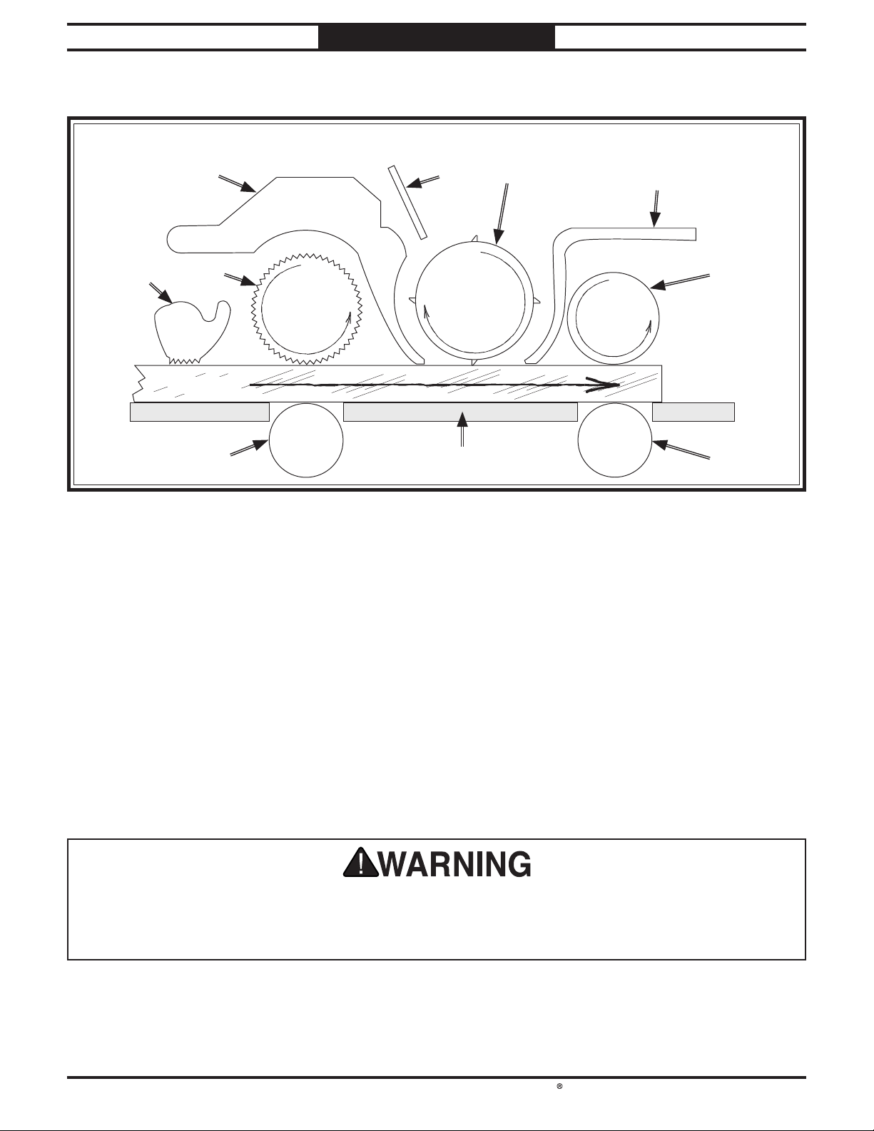
Figure 3. Workpiece path and major planing components (side cutaway view).
Workpiece
Front Rear
A
C
B
E
H HI
F
G
D
F. Pressure Bar: Stabilizes the workpiece
as it leaves the cutterhead and assists in
deflecting wood particles toward the dust
hood.
G. Outfeed Roller: Pulls the workpiece through
the planer.
H. Bed Rollers: Provide upward pressure on the
workpiece, enabling the feed rollers to pull
the workpiece along.
I. Planer Table: Provides a smooth and level
path for the workpiece as it moves through
the planer.
A. Anti-Kickback Fingers: Provide additional
safety for the operator.
B. Serrated Infeed Roller: Pulls the workpiece
toward the cutterhead.
C. Chip Breaker: Breaks off chips created by the
cutterhead to prevent tear-out and diverts
the chips to the dust hood.
D. Chip Deflector: Directs chips into the dust
hood.
E. Cutterhead: Holds the knives/indexable
carbide inserts that remove material from
the workpiece.

South Bend Tools
For Machines Mfd. Since 12/20 Model SB1108 /SB1109
-5-
INTRODUCTION
Product Specifications SB1108
Model SB1108 Page 1 of 3
Model SB1108
15" Planer with Helical Cutterhead
Product Dimensions
Weight............................................................................................................................................................. 509 lbs.
Width (side-to-side) x Depth (front-to-back) x Height............................................................... 39 x 48 x 44-1/2 in.
Footprint (Length x Width)................................................................................................................. 23 x 22-1/2 in.
Shipping Dimensions
Type.......................................................................................................................................................... Wood Crate
Content.......................................................................................................................................................... Machine
Weight............................................................................................................................................................. 595 lbs.
Length x Width x Height................................................................................................................... 27 x 37 x 52 in.
Must Ship Upright................................................................................................................................................ Yes
Electrical
Power Requirement......................................................................................................... 230V, Single-Phase, 60 Hz
Full-Load Current Rating.................................................................................................................................... 18A
Minimum Circuit Size.......................................................................................................................................... 20A
Connection Type..................................................................................................................................... Cord & Plug
Power Cord Included............................................................................................................................................. Yes
Power Cord Length.......................................................................................................................................... 120 in.
Power Cord Gauge......................................................................................................................................... 12 AWG
Plug Included........................................................................................................................................................ Yes
Included Plug Type.............................................................................................................................................. 6-20
Switch Type................................................................................ Magnetic Switch w/Thermal Overload Protection
Motors
Main
Horsepower............................................................................................................................................... 3 HP
Phase............................................................................................................................................ Single-Phase
Amps........................................................................................................................................................... 12A
Speed................................................................................................................................................ 3450 RPM
Type............................................................................................................. TEFC Capacitor-Start Induction
Power Transfer ........................................................................................................................... Triple V-Belt
Bearings.................................................................................................... Sealed & Permanently Lubricated
Centrifugal Switch/Contacts Type..................................................................................................... External
Feed
Horsepower............................................................................................................................................ 3/4 HP
Amps............................................................................................................................................................. 8A
Speed................................................................................................................................................ 2500 RPM
Type................................................................................................................................................... DC Motor
Power Transfer ........................................................................................................................... Belt & Chain
Bearings................................................................................................... Sealed & Permanently Lubricated

-6-
For Machines Mfd. Since 12/20
South Bend Tools
Model SB1108 /SB1109 INTRODUCTION
Model SB1108 Page 2 of 3
Main Specifications
Main Specifications
Planer Size............................................................................................................................................... 15 in.
Max. Cut Width....................................................................................................................................... 15 in.
Max. Cut Height........................................................................................................................................ 6 in.
Min. Stock Length..................................................................................................................................... 6 in.
Min. Stock Thickness............................................................................................................................ 3/16 in.
Number of Cuts Per Inch..................................................................................................................... 167 - 60
Number of Cuts Per Minute.................................................................................................................. 20,000
Cutterhead Speed............................................................................................................................ 5000 RPM
Planing Feed Rate........................................................................................................................ 10 - 28 FPM
Max. Cut Depth Planing Full Width................................................................................................... 3/32 in.
Max. Cut Depth Planing 6-Inch Wide Board........................................................................................ 1/8 in.
Cutterhead Info
Cutterhead Type.................................................................................................................................... Helical
Cutterhead Diameter ................................................................................................................................ 3 in.
Number of Cutter Rows.................................................................................................................................. 4
Number of Indexable Cutters....................................................................................................................... 52
Cutter Insert Type.............................................................................................................. Indexable Carbide
Cutter Insert Size Length...................................................................................................................... 15mm
Cutter Insert Size Width........................................................................................................................ 15mm
Cutter Insert Size Thickness................................................................................................................ 2.5mm
Table Info
Table/Headstock Movement...................................................................................................................... 6 in.
Table Bed Size Length............................................................................................................................. 48 in.
Table Bed Size Width.............................................................................................................................. 15 in.
Table Bed Size Thickness.......................................................................................................................... 2 in.
Number of Bed Rollers.................................................................................................................................... 2
Floor-to-Table Height....................................................................................................................... 30 - 36 in.
Table Wings Size Length......................................................................................................................... 14 in.
Table Wings Size Width.................................................................................................................. 15-1/16 in.
Construction
Table.................................................................................................................... Precision-Ground Cast Iron
Body................................................................................................................................................... Cast Iron
Stand......................................................................................................................................................... Steel
Cutterhead Assembly............................................................................................................................... Steel
Infeed Roller.............................................................................................................................. Serrated Steel
Outfeed Roller............................................................................................................................. Smooth Steel
Paint Type/Finish.................................................................................................................... Powder Coated
Other
Table/Headstock Locks............................................................................................................................... Yes
Measurement Scale................................................................................................................... Inch & Metric
Number of Dust Ports..................................................................................................................................... 1
Dust Port Size............................................................................................................................................ 4 in.
Mobile Base........................................................................................................................................... T28000
Other
Country of Origin ........................................................................................................................................... Taiwan
Warranty ......................................................................................................................................................... 1 Year
Approximate Assembly & Setup Time .......................................................................................................... 1 Hour
Serial Number Location .............................................................................................................................. ID Label
Certified by a Nationally Recognized Testing Laboratory (NRTL) ................................................................... Yes

South Bend Tools
For Machines Mfd. Since 12/20 Model SB1108 /SB1109
-7-
INTRODUCTION
Product Specifications SB1109
Model SB1109 Page 1 of 3
Model SB1109
20" Planer with Helical Cutterhead
Product Dimensions
Weight............................................................................................................................................................. 719 lbs.
Width (side-to-side) x Depth (front-to-back) x Height............................................................... 46-1/2 x 56 x 46 in.
Footprint (Length x Width)........................................................................................................... 23-1/2 x 29-1/2 in.
Shipping Dimensions
Type.......................................................................................................................................................... Wood Crate
Content.......................................................................................................................................................... Machine
Weight............................................................................................................................................................. 820 lbs.
Length x Width x Height................................................................................................................... 42 x 30 x 52 in.
Must Ship Upright................................................................................................................................................ Yes
Electrical
Power Requirement......................................................................................................... 220V, Single-Phase, 60 Hz
Full-Load Current Rating.................................................................................................................................... 27A
Minimum Circuit Size.......................................................................................................................................... 30A
Connection Type..................................................................................................................................... Cord & Plug
Power Cord Included............................................................................................................................................. Yes
Power Cord Length.......................................................................................................................................... 120 in.
Power Cord Gauge......................................................................................................................................... 10 AWG
Plug Included........................................................................................................................................................ Yes
Included Plug Type............................................................................................................................................ L6-30
Switch Type................................................................................ Magnetic Switch w/Thermal Overload Protection
Motors
Main
Horsepower.............................................................................................................................................. 5 HP
Phase............................................................................................................................................ Single-Phase
Amps........................................................................................................................................................... 23A
Speed................................................................................................................................................ 3450 RPM
Type............................................................................................................. TEFC Capacitor-Start Induction
Power Transfer ........................................................................................................................... Triple V-Belt
Bearings.................................................................................................... Sealed & Permanently Lubricated
Centrifugal Switch/Contacts Type..................................................................................................... External
Feed
Horsepower............................................................................................................................................ 3/4 HP
Amps............................................................................................................................................................. 8A
Speed................................................................................................................................................ 2500 RPM
Type................................................................................................................................................... DC Motor
Power Transfer ........................................................................................................................... Belt & Chain
Bearings.................................................................................................... Sealed & Permanently Lubricated

-8-
For Machines Mfd. Since 12/20
South Bend Tools
Model SB1108 /SB1109 INTRODUCTION
Model SB1109 Page 2 of 3
Main Specifications
Main Specifications
Planer Size............................................................................................................................................... 20 in.
Max. Cut Width....................................................................................................................................... 20 in.
Max. Cut Height........................................................................................................................................ 8 in.
Min. Stock Length..................................................................................................................................... 7 in.
Min. Stock Thickness.............................................................................................................................. 1/4 in.
Number of Cuts Per Inch..................................................................................................................... 167 - 60
Number of Cuts Per Minute.................................................................................................................. 20,000
Cutterhead Speed............................................................................................................................ 5000 RPM
Planing Feed Rate........................................................................................................................ 10 - 28 FPM
Max. Cut Depth Planing Full Width................................................................................................... 5/64 in.
Max. Cut Depth Planing 6-Inch Wide Board........................................................................................ 1/8 in.
Cutterhead Info
Cutterhead Type.................................................................................................................................... Helical
Cutterhead Diameter ......................................................................................................................... 3-1/4 in.
Number of Cutter Rows.................................................................................................................................. 4
Number of Indexable Cutters....................................................................................................................... 92
Cutter Insert Type.............................................................................................................. Indexable Carbide
Cutter Insert Size Length...................................................................................................................... 15mm
Cutter Insert Size Width........................................................................................................................ 15mm
Cutter Insert Size Thickness................................................................................................................ 2.5mm
Table Info
Table/Headstock Movement...................................................................................................................... 8 in.
Table Bed Size Length............................................................................................................................. 56 in.
Table Bed Size Width.............................................................................................................................. 20 in.
Table Bed Size Thickness.................................................................................................................... 2-1/4 in.
Number of Bed Rollers.................................................................................................................................... 2
Floor-to-Table Height....................................................................................................................... 28 - 36 in.
Table Wings Size Length......................................................................................................................... 15 in.
Table Wings Size Width.................................................................................................................... 21-1/4 in.
Construction
Table.................................................................................................................... Precision-Ground Cast Iron
Body................................................................................................................................................... Cast Iron
Stand......................................................................................................................................................... Steel
Cutterhead Assembly............................................................................................................................... Steel
Infeed Roller.............................................................................................................................. Serrated Steel
Outfeed Roller............................................................................................................................. Smooth Steel
Paint Type/Finish.................................................................................................................... Powder Coated
Other
Table/Headstock Locks............................................................................................................................... Yes
Measurement Scale................................................................................................................... Inch & Metric
Number of Dust Ports..................................................................................................................................... 1
Dust Port Size............................................................................................................................................ 5 in.
Mobile Base........................................................................................................................................... T28000
Other
Country of Origin ........................................................................................................................................... Taiwan
Warranty ......................................................................................................................................................... 1 Year
Approximate Assembly & Setup Time .......................................................................................................... 1 Hour
Serial Number Location .............................................................................................................................. ID Label
Certified by a Nationally Recognized Testing Laboratory (NRTL) ................................................................... Yes

SAFETY
South Bend Tools
For Machines Mfd. Since 12/20 Model SB1108 /SB1109
-9-
SAFETY
Understanding Risks of Machinery
Operating all machinery and machining equipment can be dangerous or relatively safe depending
on how it is installed and maintained, and the operator's experience, common sense, risk awareness,
working conditions, and use of personal protective equipment (safety glasses, respirators, etc.).
The owner of this machinery or equipment is ultimately responsible for its safe use. This
responsibility includes proper installation in a safe environment, personnel training and usage
authorization, regular inspection and maintenance, manual availability and comprehension,
application of safety devices, integrity of cutting tools or accessories, and the usage of approved
personal protective equipment by all operators and bystanders.
The manufacturer of this machinery or equipment will not be held liable for injury or property
damage from negligence, improper training, machine modifications, or misuse. Failure to read,
understand, and follow the manual and safety labels may result in serious personal injury, including
amputation, broken bones, electrocution, or death.
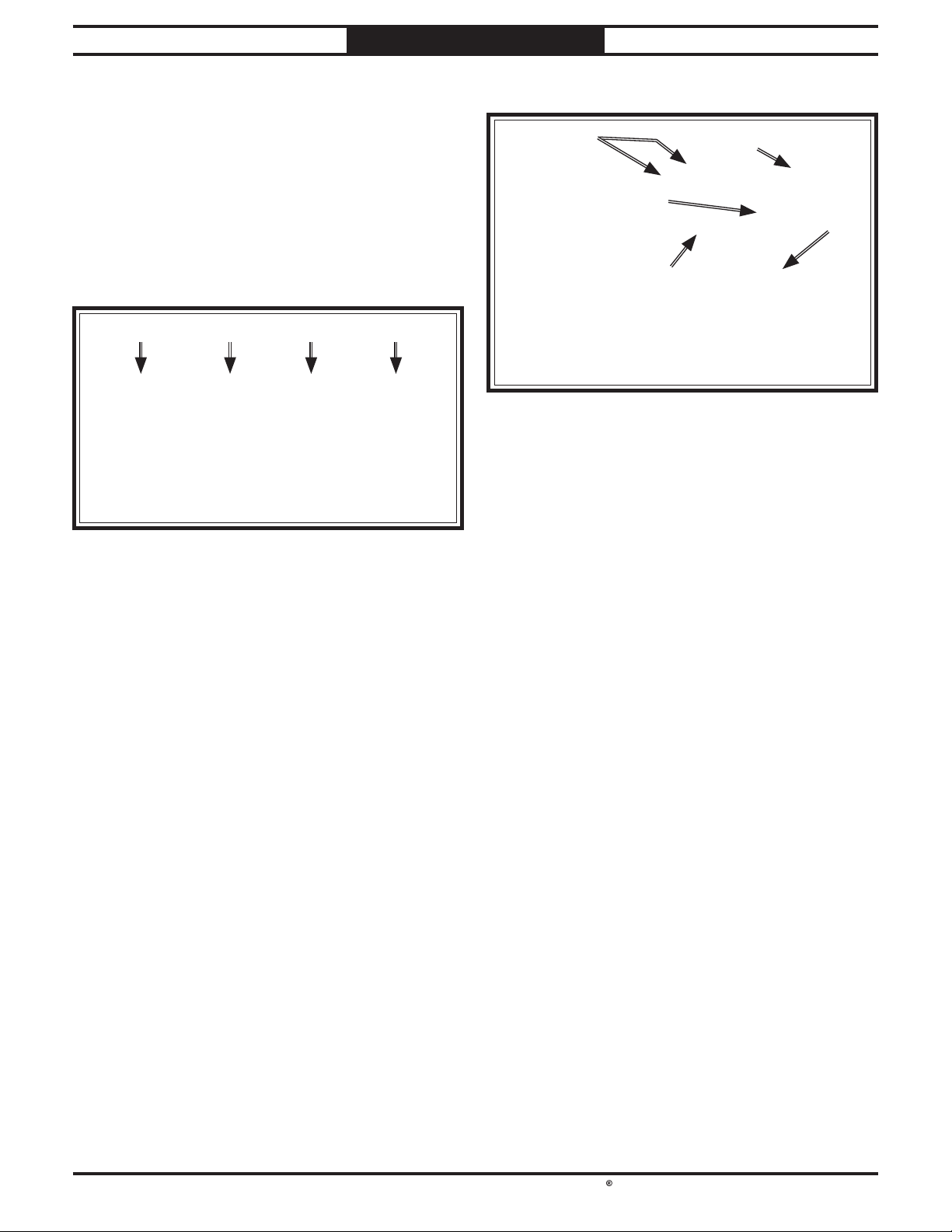
The signals used in this manual to identify hazard levels are as follows:
Death or catastrophic
harm WILL occur.
Moderate injury or fire
MAY occur.
Death or catastrophic
harm COULD occur.
Machine or property
damage may occur.
Basic Machine Safety
Owner’s Manual: All machinery and machining
equipment presents serious injury hazards
to untrained users. To reduce the risk of
injury, anyone who uses THIS item MUST
read and understand this entire manual
before starting.
Personal Protective Equipment: Operating or
servicing this item may expose the user
to flying debris, dust, smoke, dangerous
chemicals, or loud noises. These hazards
can result in eye injury, blindness, long-
term respiratory damage, poisoning,
cancer, reproductive harm or hearing loss.
Reduce your risks from these hazards
by wearing approved eye protection,
respirator, gloves, or hearing protection.
Trained/Supervised Operators Only: Untrained
users can seriously injure themselves
or bystanders. Only allow trained and
properly supervised personnel to operate
this item. Make sure safe operation
instructions are clearly understood. If
electrically powered, use padlocks and
master switches, and remove start switch
keys to prevent unauthorized use or
accidental starting.
Guards/Covers: Accidental contact with
moving parts during operation may cause
severe entanglement, impact, cutting,
or crushing injuries. Reduce this risk by
keeping any included guards/covers/doors
installed, fully functional, and positioned
for maximum protection.

-10-
For Machines Mfd. Since 12/20
South Bend Tools
Model SB1108 /SB1109 SAFETY
Entanglement: Loose clothing, gloves, neckties,
jewelry or long hair may get caught in
moving parts, causing entanglement,
amputation, crushing, or strangulation.
Reduce this risk by removing/securing
these items so they cannot contact moving
parts.
Mental Alertness: Operating this item with
reduced mental alertness increases the
risk of accidental injury. Do not let a
temporary influence or distraction lead to a
permanent disability! Never operate when
under the influence of drugs/alcohol, when
tired, or otherwise distracted.
Safe Environment: Operating electrically
powered equipment in a wet environment
may result in electrocution; operating near
highly flammable materials may result in a
fire or explosion. Only operate this item in
a dry location that is free from flammable
materials.
Electrical Connection: With electically powered
equipment, improper connections to the
power source may result in electrocution
or fire. Always adhere to all electrical
requirements and applicable codes when
connecting to the power source. Have all
work inspected by a qualified electrician to
minimize risk.
Disconnect Power: Adjusting or servicing
electrically powered equipment while it
is connected to the power source greatly
increases the risk of injury from accidental
startup. Always disconnect power
BEFORE any service or adjustments,
including changing blades or other tooling.
Secure Workpiece/Tooling: Loose workpieces,
cutting tools, or rotating spindles can
become dangerous projectiles if not
secured or if they hit another object during
operation. Reduce the risk of this hazard
by verifying that all fastening devices are
properly secured and items attached to
spindles have enough clearance to safely
rotate.
Chuck Keys or Adjusting Tools: Tools used to
adjust spindles, chucks, or any moving/
rotating parts will become dangerous
projectiles if left in place when the machine
is started. Reduce this risk by developing
the habit of always removing these tools
immediately after using them.
Work Area: Clutter and dark shadows increase
the risks of accidental injury. Only operate
this item in a clean, non-glaring, and well-
lighted work area.
Properly Functioning Equipment: Poorly
maintained, damaged, or malfunctioning
equipment has higher risks of causing
serious personal injury compared to
those that are properly maintained.
To reduce this risk, always maintain
this item to the highest standards and
promptly repair/service a damaged or
malfunctioning component. Always follow
the maintenance instructions included in
this documentation.
Unattended Operation: Electrically powered
equipment that is left unattended while
running cannot be controlled and is
dangerous to bystanders. Always turn the
power OFF before walking away.
Health Hazards: Certain cutting fluids and
lubricants, or dust/smoke created when
cutting, may contain chemicals known to
the State of California to cause cancer,
respiratory problems, birth defects,
or other reproductive harm. Minimize
exposure to these chemicals by wearing
approved personal protective equipment
and operating in a well ventilated area.
Difficult Operations: Attempting difficult
operations with which you are unfamiliar
increases the risk of injury. If you
experience difficulties performing the
intended operation, STOP! Seek an
alternative method to accomplish the
same task, ask a qualified expert how the
operation should be performed, or contact
our Technical Support for assistance.

South Bend Tools
For Machines Mfd. Since 12/20 Model SB1108 /SB1109
-11-
SAFETY
Additional Planer Safety
Amputation, serious cuts, entanglement, or death can occur from contact with rotating cutterhead or
other moving parts! Flying chips can cause eye injuries or blindness. Workpieces or knives thrown
by cutterhead can strike nearby operator or bystanders with deadly force. To reduce the risk of these
hazards, operator and bystanders MUST completely heed hazards and warnings below.
Planing Correct Material: Only plane natural
wood stock with this planer. DO NOT
plane MDF, OSB, plywood, laminates
or other synthetic materials that can
break up inside the planer and be ejected
towards the operator.
Looking Inside Planer: Wood chips fly around
inside the planer at a high rate of speed
during operation. To avoid injury from
flying material, DO NOT look inside
planer during operation.
Cutting Limitations: To reduce the risk of
kickback hazards or damage to the
machine, do not exceed the maximum
depth of cut or minimum board length and
thickness found in the Data Sheet. Only
feed one board at a time.
Infeed Roller Clearance: The infeed roller
is designed to pull material into the
spinning cutterhead. To reduce the risk
of entanglement, keep hands, clothing,
jewelry, and long hair away from the
infeed roller during operation.
Feed Workpiece Properly: To reduce the risk
of kickback, never start planer with
workpiece touching cutterhead. Allow
cutterhead to reach full speed before
feeding, and do not change feed speed
during cutting operation.
Workpiece Support: To reduce the risk of
kickback, always make sure workpiece
can move completely across table without
rocking or tipping. Use auxiliary support
stands for long stock.
Secure Knives/Inserts: Loose knives or
improperly set inserts can become
dangerous projectiles or cause machine
damage. Always verify knives/inserts
are secure and properly adjusted before
operation.
Kickback:
Know how to reduce the risk of
kickback and kickback-related injuries.
“Kickback” occurs during the operation
when the workpiece is ejected back from the
infeed side of the machine at a high rate
of speed. Kickback is commonly caused by
poor workpiece selection, unsafe feeding
techniques, or improper machine setup/
maintenance. Kickback injuries typically
occur as follows: (1) operator/bystanders
are struck by the workpiece, resulting in
impact injuries (i.e., blindness, broken bones,
bruises, death); (2) operator’s hands are
pulled into the machine from the outfeed
side, resulting in amputation or severe
lacerations.
Avoid Contact with Moving Parts:
Never remove
guards/covers or reach inside the planer
during operation or while connected to
power. You could be seriously injured if you
accidentally touch the spinning cutterhead
or get entangled in moving parts. If a
workpiece becomes stuck or sawdust removal
is necessary, turn planer OFF, allow
cutterhead to stop, and disconnect power
before clearing.
Dull/Damaged Knives/Inserts:
Only use sharp,
undamaged knives/inserts. Dull or damaged
knives/inserts increase the risk of kickback.
Inspecting Stock:
To reduce the risk of kickback
injuries or machine damage, thoroughly
inspect and prepare the workpiece before
cutting. Verify workpiece is free of nails,
staples, loose knots, or foreign material.
Workpieces with minor warping should be
jointed first or planed with the cupped side
facing the table.
Body Placement:
Stand to one side of planer
during the entire operation to avoid getting
hit if kickback occurs.
Grain Direction:
Planing across the grain is hard
on the planer and may cause kickback. Plane
in the same direction or at a slight angle
with the wood grain.

PREPARATION
-12-
For Machines Mfd. Since 12/20
South Bend Tools
Model SB1108 /SB1109 PREPARATION
Preparation Overview Required for Setup
The items listed below are required to
successfully set up and prepare this machine for
operation.
For Lifting
• A forklift or other power lifting device rated
for the weight of the machine.
• Lifting Strap or Chain (rated for at least 1000
lbs.)
For Power Connection
• A power source that meets the minimum cir-
cuit requirements for this machine. (Refer to
the Power Supply Requirements on Page
13 for details.)
For Assembly
• Safety Glasses (for each person)
• Straightedge 4' (or longer)
• Dust Collection System
• 4" Dust Hose (for SB1108)
• 4" Hose Clamp (for SB1108)
• 5" Dust Hose (for SB1109)
• 5" Hose Clamp (for SB1109)
• Disposable Rags
• Disposable Gloves
• Cleaner/Degreaser
• Gearbox Oil
• Phillips Head Screwdriver #2
• Open-End Wrench 8mm (for SB1108)
• Open-End Wrench 17mm (for SB1109)
The purpose of the preparation section is to help
you prepare your machine for operation. The list
below outlines the basic process. Specific steps
for each of these points will be covered in detail
later in this section.
The typical preparation process is as follows:
1. Unpack the machine and inventory the
contents of the box/crate.
2. Clean the machine and its components.
3. Identify an acceptable location for the
machine and move it to that location.
4. Level the machine using the pre-installed
machine mounts.
5. Assemble the loose components and make
any necessary adjustments or inspections to
ensure the machine is ready for operation.
6. Connect the machine to the power source.
7. Test run the machine to make sure it
functions properly and is ready for operation.

South Bend Tools
For Machines Mfd. Since 12/20 Model SB1108 /SB1109
-13-
PREPARATION
Electrocution or fire may
occur if machine is not
correctly grounded and
attached to the power
supply. Use a qualified
electrician to ensure a safe
power connection.
Before installing the machine, consider the
availability and proximity of the required power
supply circuit. If an existing circuit does not meet
the requirements for this machine, a new circuit
must be installed.
To minimize the risk of electrocution, fire,
or equipment damage, installation work and
electrical wiring must be done by a
n electrician
or qualified service personnel
in accordance with
applicable electrical codes and safety standards.
Availability
The full-load current rating is the amperage
a machine draws at 100% of the rated output
power. On machines with multiple motors, this is
the amperage drawn by the largest motor or sum
of all motors and electrical devices that might
operate at one time during normal operations.
The full-load current is not the maximum
amount of amps that the machine will draw. If
the machine is overloaded, it will draw additional
amps beyond the full-load rating.
If the machine is overloaded for a sufficient
length of time, damage, overheating, or fire may
result—especially if connected to an undersized
circuit. To reduce the risk of these hazards,
avoid overloading the machine during operation
and make sure it is connected to a power supply
circuit that meets the requirements in the
following section.
Full-Load Current Rating at 220V
SB1108 Full-Load Rating ................... 18 Amps
SB1109 Full-Load Rating ................... 27 Amps
Circuit Information
For your own safety and protection of property,
consult an electrician if you are unsure about
wiring practices or applicable electrical codes.
Note: The circuit requirements in this manual
are for
a dedicated circuit—where only one
machine will be running at a time. If this
machine will be connected to a shared circuit
where multiple machines will be running at
the same time, consult a qualified electrician to
ensure the circuit is properly sized.
A power supply circuit includes all electrical
equipment between the main breaker box or fuse
panel in your building and the incoming power
connections inside the machine. This circuit
must be safely sized to handle the full-load
current that may be drawn from the machine for
an extended period of time. (If this machine is
connected to a circuit protected by fuses, use a
time delay fuse marked D.)
Grounding Requirements
This machine must be grounded! In the event
of
certain types of malfunctions or breakdowns,
grounding provides a path of least resistance
for electric current
in order to reduce the risk of
electric shock.
Improper connection of the equipment-grounding
wire can result in a risk of electric shock. The
wire with green insulation (with or without
yellow stripes) is the equipment-grounding wire.
If repair or replacement of the power cord or
plug is necessary, do not connect the equipment-
grounding wire to a live (current carrying)
terminal.
Check with an electrician or qualified service
personnel if you do not understand these
grounding requirements, or if you are in doubt
about whether the tool is properly grounded.
If you ever notice that a cord or plug is
damaged or worn, disconnect it from power, and
immediately replace it with a new one.
Power Supply
Requirements
Power supply requirements

-14-
For Machines Mfd. Since 12/20
South Bend Tools
Model SB1108 /SB1109 PREPARATION
No adapter should be used with plug. If
plug does not fit available receptacle, or if
machine must be reconnected for use on a
different type of circuit, reconnection must
be performed by an electrician or qualified
service personnel, and it must comply with all
local codes and ordinances.
SB1108 Circuit Requirements
This machine is prewired to operate on a power
supply circuit that has a verified ground and
meets the following requirements:
This machine is prewired to operate on a power
supply circuit that has a verified ground and
meets the following requirements:
SB1109 Circuit Requirements
Nominal Voltage ........ 208V, 220V, 230V, 240V
Cycle .............................................................60 Hz
Phase ..............................................Single-Phase
Circuit Rating....................................... 30 Amps
Plug/Receptacle (included) ........ NEMA L6-30
This machine is equipped with a power cord
that has
an equipment-grounding wire and a
grounding plug
(similar to the figure below).
The plug
must only be inserted into a matching
receptacle (outlet)
that is properly installed and
grounded in accordance with all local codes and
ordinances.
Grounding Prong
is Hooked
Current Carrying Prongs
GROUNDED
L6-30 LOCKING
RECEPTACLE
L6-30
LOCKING
PLUG
Figure 5. NEMA L6-30 plug and receptacle.
Nominal Voltage ........ 208V, 220V, 230V, 240V
Cycle .............................................................60 Hz
Phase ..............................................Single-Phase
Circuit Rating....................................... 20 Amps
Plug/Receptacle (included) ...........NEMA 6-20
This machine is equipped with a power cord
that has
an equipment-grounding wire and a
grounding plug
(similar to the figure below).
The plug
must only be inserted into a matching
receptacle (outlet)
that is properly installed and
grounded in accordance with all local codes and
ordinances.
Extension Cords
SB1108 .............................. 12 AWG, 50 ft or less
SB1109 .............................. 10 AWG, 50 ft or less
We do not recommend using an extension cord
with this machine. If you must use one, only
use it if absolutely necessary and only on a
temporary basis.
Extension cords cause voltage drop, which may
damage electrical components and shorten motor
life. Voltage drop increases as the extension cord
size gets longer and the gauge size gets smaller
(higher gauge numbers indicate smaller sizes).
Any extension cord used with this machine
must contain a ground wire, match the required
plug and receptacle listed in the
Circuit
Requirements
for the applicable voltage, and
meet the following requirements:
Figure 4. NEMA 6-20 plug and receptacle.
Grounding Prong
Current Carrying Prongs
6-20 PLUG
GROUNDED
6-20 RECEPTACLE
South Bend Tools
For Machines Mfd. Since 12/20 Model SB1108 /SB1109
-15-
PREPARATION
Unpacking
This item was carefully packaged to prevent
damage during transport. If you discover any
damage, please immediately call Customer
Service at (360) 734-1540 for advice. You may
need to file a freight claim, so take pictures and
save all the containers and packing materials for
possible inspection by the carrier or its agent.
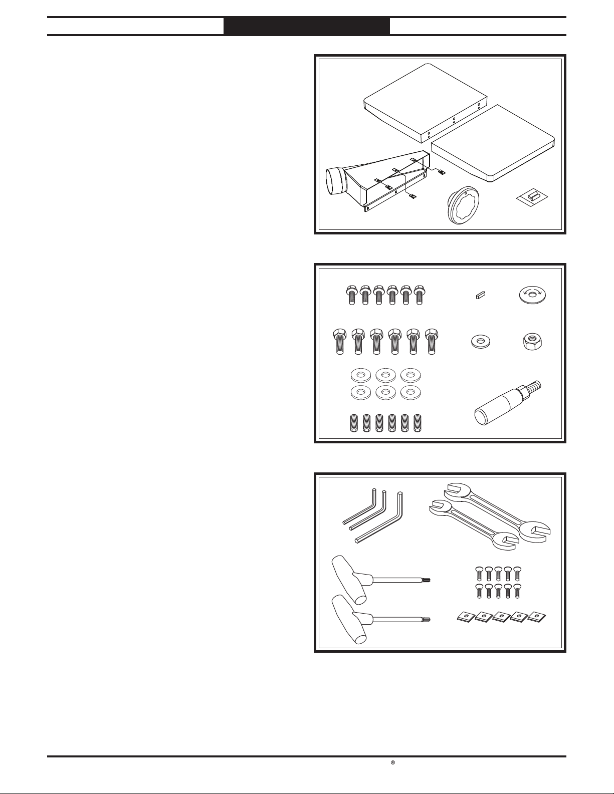
Inventory
Figure 6. SB1108 assembly components.
B
C
D E
Figure 7. SB1108 assembly hardware.
LOW HIGH
F G H
IJK
L
M
Wood Crate (Figures 6–8) Qty
A. Planer Unit (Not Shown)............................... 1
B. Extension Tables............................................2
C. Dust Hood.......................................................1
D. Handwheel .....................................................1
E. Batteries AAA ................................................2
F. Flange Bolts M6-1 x 12 (Dust Port) .............. 6
G. Machine Key 4 x 4 x 10 (Handwheel) ........... 1
H. Direction Label (Handwheel) ........................1
I. Hex Bolts M8-1.25 x 25 (Ext. Table) ............. 6
J. Flat Washer 10mm (Handwheel) .................. 1
K. Hex Nut M10-1.25 (Handwheel) ................... 1
L. Flat Washers 8mm (Ext. Table) ....................6
M. Set Screws M8-1.25 x 12 (Ext. Table) ...........6
N. Handwheel Handle ........................................1
O. Hex Wrench Set 3, 4, 6mm ...................1 Each
P. Open-End Wrench 10/13mm ......................... 1
Open-End Wrench 12/14mm ......................... 1
Q. T-Handle Torx Wrenches T-25 ...................... 2
R. Flat Head Torx Screws #10-32 x 1⁄2"............10
S. Indexable Carbide Inserts 15 x 15 x 2.5mm.5
Figure 8. SB1108 tools and inserts.
O P
Q
S
R
The following is a list of items shipped with your
machine. Before beginning setup, lay these items
out and inventory them.
If any non-proprietary parts are missing (e.g. a
nut or a washer), we will gladly replace them; or
for the sake of expediency, replacements can be
obtained at your local hardware store.
SB1108
N
-16 -
For Machines Mfd. Since 12/20
South Bend Tools
Model SB1108 /SB1109 PREPARATION
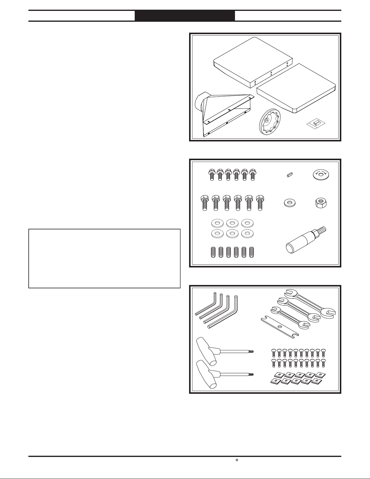
SB1109
Figure 9. SB1109 assembly components.
B
C
D
E
Figure 10. SB1109 assembly hardware.
LOW HIGH
F G H
IJ K
L
M
N
NOTICE
If you cannot find an item on this list, carefully
check around/inside the machine and
packaging materials. Often, these items get
lost in packaging materials while unpacking or
they are pre-installed at the factory.
Wood Crate (Figures 9–11) Qty
A. Planer Unit (Not Shown)............................... 1
B. Extension Tables............................................2
C. Dust Hood.......................................................1
D. Handwheel .....................................................1
E. Batteries AAA ................................................2
F. Flange Bolts M6-1 x 12 (Dust Hood)............. 6
G. Machine Key 4 x 4 x 10 (Handwheel) ........... 1
H. Direction Label (Handwheel) ........................1
I. Hex Bolts M8-1.25 x 25 (Ext. Table) ............. 6
J. Flat Washer 10mm (Handwheel) .................. 1
K. Hex Nut M10-1.25 (Handwheel) ................... 1
L. Flat Washers 8mm (Ext. Table) ....................6
M. Set Screws M8-1.25 x 12 (Ext. Table) ...........6
N. Handwheel Handle ........................................1
O. Hex Wrench Set 3–6mm .......................1 Each
P. Open-End Wrench 8/10mm ........................... 1
Open-End Wrench 10/13mm ......................... 1
Open-End Wrench 12/14mm ......................... 1
Open-End Wrench 17/19mm ......................... 1
Q. T-Handle Torx Wrenches T-25 ...................... 2
R. Flat Head Torx Screws #10-32 x 1⁄2"............20
S. Indexable Carbide Inserts 15 x 15 x 2.5mm . 10
Figure 11. SB1109 tools and inserts.
R
O P
Q
S

South Bend Tools
For Machines Mfd. Since 12/20 Model SB1108 /SB1109
-17-
PREPARATION
Cleaning & Protecting
Figure 12. T23692 Orange Power Degreaser.
The unpainted surfaces are coated
at the factory
with a heavy-duty rust preventative that
prevents corrosion during shipment and
storage.
The benefit of this rust preventative is that it
works very well. The downside is that it
can be
time-consuming
to thoroughly remove.
Be patient and do a careful job when
cleaning
and removing the rust preventative
. The time
you spend doing this will reward you with
smooth
-sliding parts and a better appreciation
for the proper care of
the unpainted surfaces.
Although there are many ways to successfully
remove the rust preventative, the
following
process works well in most situations
.
Before cleaning, gather the following:
• Disposable
rags
• Cleaner/degreaser
(certain citrus-based
degreasers work extremely well and they
have non-toxic fumes)
• Safety glasses & disposable gloves
Note:
Automotive degreasers, mineral spirits, or
WD•40 can be used to remove rust preventative.
Before using these products, though, test them
on an inconspicuous area of a painted surface to
make sure they will not damage it.
GAS
Gasoline and petroleum
products have low flash
points and can explode
or cause fire if used for
cleaning. Avoid using these
products to remove rust
preventative.
Many cleaning solvents are
toxic if inhaled. Minimize
your risk by only using
these products in a well
ventilated area.
Avoid chlorine-based solvents, such as
acetone or brake parts cleaner that may
damage painted surfaces. Always follow the
manufacturer’s instructions when using any
type of cleaning product.
Basic steps for removing rust preventative:
1. Put on safety glasses and disposable gloves.
2. Coat all surfaces that have rust preventative
with a liberal amount of your cleaner or
degreaser and let them soak for a few
minutes.
3. Wipe off the surfaces. If your cleaner or
degreaser is effective, the rust preventative
will wipe off easily.
Note: To clean off thick coats of rust
preventative on flat surfaces, such as beds
or tables, use a PLASTIC paint scraper to
scrape off the majority of the coating before
wiping it off with your rag. (Do not use a
metal scraper or it may scratch the surface.)
4. Repeat Steps 2–3 as necessary until clean,
then coat all unpainted surfaces with a
quality metal protectant or light oil to
prevent rust.
T23692—Orange Power Degreaser
A great product for removing the waxy shipping
grease from the non-painted parts of the
machine during clean up.
-18-
For Machines Mfd. Since 12/20
South Bend Tools
Model SB1108 /SB1109 PREPARATION
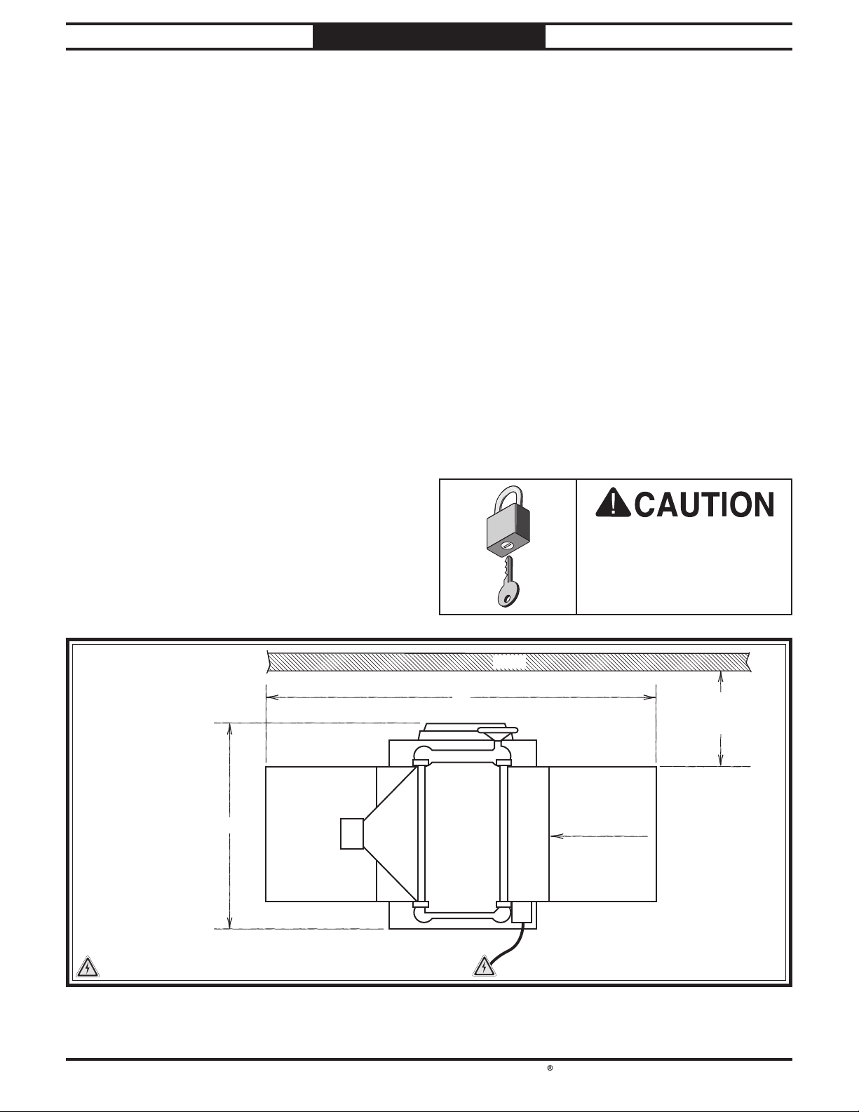
YFeed DirectionDust
Po r t
Model SB1109
Y = 46 1/2"
X = 56"
Model SB1108
Y = 39"
X = 48"
Min. 30"
for Maintenance
Wall
= Electrical Connection
X
Figure 13. Minimum working clearances.
Physical Environment
Electrical Installation
Lighting
Weight Load
Space Allocation
Weight Load
Refer to the Machine Specifications for the
weight of your machine. Make sure that the
surface upon which the machine is placed will
bear the weight of the machine, additional
equipment that may be installed on the machine,
and the heaviest workpiece that will be used.
Additionally, consider the weight of the operator
and any dynamic loading that may occur when
operating the machine.
Space Allocation
Consider the largest size of workpiece that will
be processed through this machine and provide
enough space around the machine for adequate
operator material handling or the installation
of auxiliary equipment. With permanent
installations, leave enough space around
the machine to open or remove doors/covers
as required by the maintenance and service
described in this manual.
Physical Environment
The physical environment where your machine
is operated is important for safe operation and
longevity of
parts. For best results, operate this
machine in a dry environment that is free from
excessive moisture, hazardous
or flammable
chemicals, airborne abrasives, or extreme
conditions. Extreme conditions for this type
of machinery are generally those where the
ambient temperature
is outside the range of 41°–
104°F; the relative humidity
is outside the range
of
20–95% (non-condensing); or the environment
is subject to vibration, shocks, or bumps.
Electrical Installation
Place this machine near an existing power
source. Make sure all power cords are protected
from traffic, material handling, moisture,
chemicals, or other hazards. Make sure to leave
access to a means of disconnecting the power
source or engaging a lockout/tagout device.
Lighting
Lighting around the machine must be adequate
enough to perform operations safely. Shadows,
glare, or strobe effects that may distract or
impede the operator must be eliminated.
Children or untrained
people may be seriously
injured by this machine.
Only install in an access
restricted location.
Location
This manual suits for next models
1
Table of contents
Other Southbend Planer manuals


 manual")


