WoodFast PL200A User manual

Instruction
Manual
IMPORTANT
For your safety, read
instructions carefully
before assembling or
using this product.
Save this manual for
future reference.
/RIGINAL¬)NSTRUCTION¬-ANUAL
6ERSION¬
&EBRUARY¬
7OODWORKING¬-ACHINES¬¬!CCESSORIES
4ELEPHONE¬¬¬
&AX¬¬¬
3TARTRITE
5NIT¬"¬!DELPHI¬7AY
3TAVELEY¬¬3¬,3
%MAIL¬SALES RECORDPOWERCOUK
WWWSTARTRITECOUK
%¬%¬¬%¬¬¬
)NDUSTRIAL¬¬
"ANDSAW
)-0/24!.4
&OR¬YOUR¬SAFETY¬READ¬INSTRUCTIONS¬CAREFULLY¬BEFORE¬
ASSEMBLING¬OR¬USING¬THIS¬PRODUCT¬3AVE¬THIS¬
MANUAL¬FOR¬FUTURE¬REFERENCE
(%!,4(¬!.$¬3!&%49¬'5)$%,).%3
!LWAYS¬FOLLOW¬THE¬INSTRUCTIONS¬PROVIDED¬WITH¬THE¬MANUAL¬!LWAYS¬WEAR¬SAFETY¬GLASSES¬WHEN¬USING¬WOODWORKING¬
EQUIPMENT¬!LWAYS¬DISCONNECT¬THE¬POWER¬BEFORE¬ADJUSTING¬ANY¬EQUIPMENT¬&AILURE¬TO¬OBSERVE¬PROPER¬SAFETY¬
PROCEDURES¬AND¬GUIDELINES¬CAN¬RESULT¬IN¬SERIOUS¬INJURY
7!2.).'¬$O¬NOT¬ALLOW¬FAMILIARITY¬GAINED¬FROM¬FREQUENT¬USE¬OF¬YOUR¬MACHINE¬AND¬ACCESSORIES¬TO¬BECOME¬
COMMONPLACE¬!LWAYS¬REMEMBER¬THAT¬A¬CARELESS¬FRACTION¬OF¬A¬SECOND¬IS¬SUFlCIENT¬TO¬INmICT¬SEVERE¬INJURY !LWAYS¬WEAR¬SAFETY¬GLASSES¬WHEN¬
USING¬WOODWORKING¬EQUIPMENT
!LWAYS¬READ¬THE¬INSTRUCTIONS¬
PROVIDED¬BEFORE¬USING¬
WOODWORKING¬EQUIPMENT
Wood Planer
PL200A
Version: V.1-201810
/RIGINAL¬)NSTRUCTION¬-ANUAL
6ERSION¬
&EBRUARY¬
7OODWORKING¬-ACHINES¬¬!CCESSORIES
4ELEPHONE¬¬¬
&AX¬¬¬
3TARTRITE
5NIT¬"¬!DELPHI¬7AY
3TAVELEY¬¬3¬,3
%MAIL¬SALES RECORDPOWERCOUK
WWWSTARTRITECOUK
%¬%¬¬%¬¬¬
)NDUSTRIAL¬¬
"ANDSAW
)-0/24!.4
&OR¬YOUR¬SAFETY¬READ¬INSTRUCTIONS¬CAREFULLY¬BEFORE¬
ASSEMBLING¬OR¬USING¬THIS¬PRODUCT¬3AVE¬THIS¬
MANUAL¬FOR¬FUTURE¬REFERENCE
(%!,4(¬!.$¬3!&%49¬'5)$%,).%3
!LWAYS¬FOLLOW¬THE¬INSTRUCTIONS¬PROVIDED¬WITH¬THE¬MANUAL¬!LWAYS¬WEAR¬SAFETY¬GLASSES¬WHEN¬USING¬WOODWORKING¬
EQUIPMENT¬!LWAYS¬DISCONNECT¬THE¬POWER¬BEFORE¬ADJUSTING¬ANY¬EQUIPMENT¬&AILURE¬TO¬OBSERVE¬PROPER¬SAFETY¬
PROCEDURES¬AND¬GUIDELINES¬CAN¬RESULT¬IN¬SERIOUS¬INJURY
7!2.).'¬$O¬NOT¬ALLOW¬FAMILIARITY¬GAINED¬FROM¬FREQUENT¬USE¬OF¬YOUR¬MACHINE¬AND¬ACCESSORIES¬TO¬BECOME¬
COMMONPLACE¬!LWAYS¬REMEMBER¬THAT¬A¬CARELESS¬FRACTION¬OF¬A¬SECOND¬IS¬SUFlCIENT¬TO¬INmICT¬SEVERE¬INJURY !LWAYS¬WEAR¬SAFETY¬GLASSES¬WHEN¬
USING¬WOODWORKING¬EQUIPMENT
!LWAYS¬READ¬THE¬INSTRUCTIONS¬
PROVIDED¬BEFORE¬USING¬
WOODWORKING¬EQUIPMENT

-2-
INDEX
1 GENERAL INFORMATION
1.1 FOREWORD
1.2 MACHINE IDENTIFICATION
1.3 CUSTOMER SERVICE RECOMMENDATIONS
2 SAFETY PRECAUTIONS
2.1 SAFETY REGULATIONS
2.2 RESIDUAL RISKS
2.3 SAFETY AND INFORMATION SIGNALS
3 SPECIFICATIONS
3.1 MAIN COMPONENTS
3.2 TECHNICAL SPECIFICATION
3.3 NOISE LEVEL
3.4 DUST EXTRACTION
4. INSTALLATION
4.1 CONTENTS OF PACKAGE
4.2 INSTALLATION
4.3 INSTALLATION TIP
5. FITTING AND OPERATING OF MACHINE
5.1 FITTING OF MACHINE
5.2 DRIVE BELT INSTALLATION
5.3 DRIVE BELT & PULLEY ALIGNMENT
5.4 INSTALLING THE FENCE
5.5 DUST PORT ASSEMBLY
5.6 INSTALLING THE CUTTERHEAD GUARD
5.7 INSTALLING THE INFEED TABLE LEVER
5.8 OUTFEED TABLE ADJUSMENT KNOB
5.9 SWITCH POST INSTALLATION
6. OPERATION
6.1 STARTING AND STOPPING JOINTER
6.2 DIRECTION OF GRAIN
6.3 JOINTER OPERATION
6.4 FEEDING THE WORKPIECE
6.5 SETTING DEPTH OF CUT
6.6 FENCE ADJUSTMENTS
6.7 SETTING THE FENCE TO 90° and 135°
7 ADJUSTMENTS
7.1 ROTATING OR REPLACING KNIFE INSERTS
7.2 TABLE ADJUSTMENTS
7.3 CHANGING THE DRIVE BELT
8 MAINTENANCE
9 TROUBLESHOOTING
10 WIRING DIAGRAM
11 ACCESSORIES
12 PARTS DIAGRAM

-3-
1. GENERAL INFORMATION
1.1 FOREWORD
The present manual is designed for those who will operate the machine. You will find in it the necessary data for
commissioning, maintenance and safety operation of the machine. The experience of the company manufacturer and its
experts in considered in the preparation of this manual.
We recommend you to consider with responsibility our recommendations concerning the safety of work. The operations
requiring disassembly of machine and electrical components should be performed by authorized and qualified personnel
only. Repairs and settings not described in the present manual should not be performed. This manual is prepared by
the manufacturer and is an integral part of the machine’s delivery. The information contained herein is intended for
specialists and is compulsory.
The manual defines the machine’s field of application and contains all the information necessary for its proper and
safety operation. The permanent and exact observation of the instructions contained in this manual ensure safety of
personnel and machine, profitable work as well as long life of the machine itself. For better clarity this manual is divided
in separate parts in which are contained the more important subjects.
The contents will allow you to find fast the specific subjects. The important text is printed in bold and is marked by the
following symbols:
1.2 MACHINE IDENTIFICATION
There is a identification plate fixed to the machine, containing the manufacturer's data, year of construction, serial
number and technical specifications.
1.3 CUSTOMER SERVICE RECOMMENDATIONS
Apply the machine to skilled and authorized technical staff to carry out any operation dealing with parts disassembly.
Keep to the instructions contained in this manual for the correct use of the machine.
Only skilled and authorized staff shall use and service the machine after reading this manual.
Respect the accident prevention regulations and the general safety and industrial medicine rules.
Indicates imminent risks which may cause serious injury to the operator or other persons. Be
careful and scrupulously follow the instructions.
A statement advising of the need to take care lest serious consequences result in harm to
material items such as the asset or the product.
CAUTION
WARNING
CAUTION

-4-
2. SAFETY PRECAUTIONS
2.1 SAFETY REGULATIONS
- Woodworking machine is high speed and high-risk equipment, so operator who is been suitably trained can use the
machine for safety production.
-The manufacturer disclaims all responsibilities for damages to persons or things, which might be caused by any failure
to comply with the safety regulations.
-The manufacturer disclaims all responsibilities for damages to persons or things, which might be caused by any failure
of electrical installation or nonstandard assembly.
- The manufacturer is not responsible for any damage deriving from arbitrary modifications made to the machine.
- It is prohibited to use the machine when under the influence of alcohol, drugs or medication.
- All the operators must be suitably trained for use, adjustment and operation of the machine.
- The operators must carefully read the manual paying particular attention to the warning and safety notes. Furthermore,
they must be informed on the dangers associated with use of the machine and the precautions to be taken, and must
be instructed to periodically inspect the guards and safety devices.
- Before changing the blade, debugging the trouble, carrying out adjustment, or cleaning work, disconnect the machine
from the electric power by setting the main switch to stop to make sure the machine will not being operated wrongly.
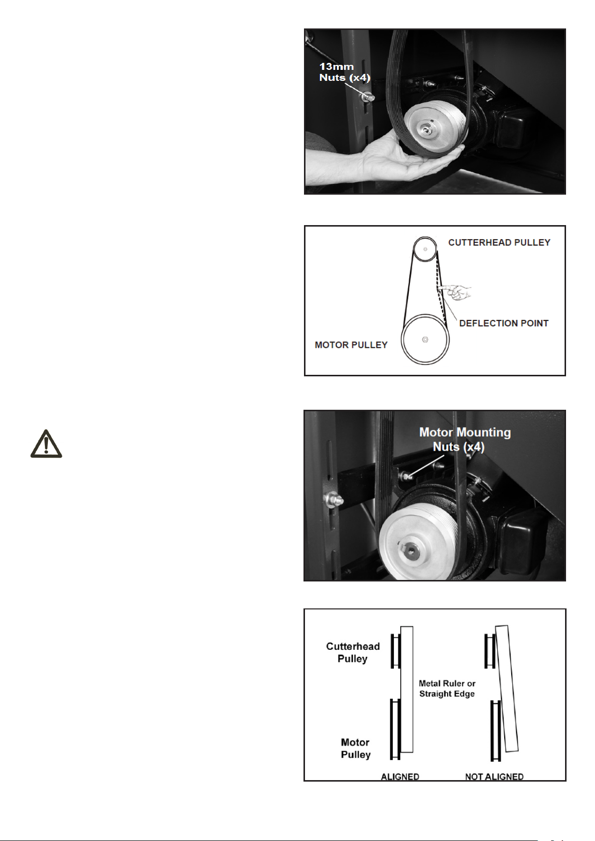
- After an initial bedding-in period or many hours of operation, the driving belts may slacken; this causes an increase in
the tool stopping time. Immediately tighten them.
- The working area around the machine must be kept always clean and clear, in order to have an immediate and easy
access to the switchboard.
- Never insert materials which are different from those which are prescribed for the machine utilization. The material to
be machined must not contain any metal parts.
- Never machine pieces which may be too small or too wide ithrespect to the machine capacity.
- Do not work wood which has evident defects (cracks, knots, metal parts, etc.)
- Never place hands among the moving parts and/or materials.
- Keep the tools tidy and far away from those not authorized persons.
- Never employ cracked nor uckled, neither not correctly reground tools. Nonstandard or blunt tools are forbidden,
either. Blade with broken edge or out of shape should not be used.
- Never use the tools beyond the speed limit recommended by the producers.
- Carefully clean the rest surfaces of tools and make sure that they find perfectly horizontally positioned, and with no
dents at all.
- Always wear gauntlets when handling the tools.
- Mount the tools in the right machining direction.
- Never start the machine before having correctly installed all the protections. The protection device should be installed
before starting the machine. The protection device should not be removed.
WARNING

-5-
- Connect the dust suction hoods to an adequate suction system; suction must always be activated when the machine is
switched on.
- Never open doors or protections when the machine or the system is operating.
- Please check if the blade lock well and the cutter shaft has the right direction. The rotating should get up to the stable
condition before working.
- Many unpleasant experiences have shown that anybody may wear objects which could cause serious accidents.
Therefore, before starting working, take any bracelet, watch or ring off.
- Button the working garment sleeve well around the wrists.
- Take any garment off which, by hanging out, may get tangled in the MOVING UNITS.
-Always wear strong working footwear, as prescribed by the accident-prevention regulations of all countries. Use
protection glasses. Use appropriate hearing protection systems (headsets, earplugs, etc.) and dust protection masks.
- Never let unauthorized people repair, service or operate the machine.
- The manufacturer is not responsible for any damage deriving from arbitrary modifications made to the machine.
- Any transport, assembly and dismantling is to be made only by trained staff, who shall have specific skill for the
specified operation.
- The operator must never leave the machine unattended during operation.
- During any working cycle break, switch the machine off.
- In case of long working cycle breaks, disconnect the general power supply.
- The operating method to be followed in the event of accident or breakdown, the machine should be turned off
immediately and unplug from main power and ask for assistance for the authorized people. If a blockage is likely to
occur, the workpiece should be move back a little and enable the equipment to be safely unblocked.
- Please remove unnecessary sweeping, chips, in case of accidents.
- Woodworking machine will produce sparks when using with serious fire risks, so please keep the machine surrounding
area clean without inflammables and explosives.

2.2 RESIDUAL RISKS
Despite observance of all the safety regulations, and use according to the rules described in this manual, residual risks
may still be present, among which the most recurring are:
- contact with tool
- contact with moving parts (belts, pulleys, etc..)
- recoil of the piece or part of it
- accidents due to wood splinters or fragments
- tool insert ejection
- electrocution from contact with live parts
- danger due to incorrect tool installation
- inverse tool rotation due to incorrect electrical connection
- danger due to dust inhalation in case of working without vacuum cleaner.
2.3 SAFETY AND INFORMATION SIGNALS
This signals may be applied on the machine; in some cases they indicate possible danger conditions, in others they
serve as indication.
Always take the utmost care.
SAFETY SIGNALS:
Risk of eye injury. Wear eye protection.
Wear hearing protection systems.
Danger of electric shock. Do not access the area when the machine is powered.
Carefully read and understand the manual before using the machine.
INFORMATION SIGNALS:
Indicate the technical characteristics, direction of rotation and inclination, block and release, etc.
Carefully following the directions to simply the use and adjustment of the machine.
The signals are graphically described and do not require further explanation.
-6-

3.2 TECHNICAL SPECIFICATION
-7-
3. SPECIFICATIONS
3.1 MAIN COMPONENTS
Items Parameters
Cutterblock Speed 4400RPM
Cutterblock Diameter 76mm
Max Cutting Width 200mm
Max Cutting Depth 3mm
Max. Rabbeting Cat 13mm
Number of Tips 40pcs
Tips Size 14mm x 14mm x 2mm
Table Size 1865x238mm
Extractor Port Dia. 100mm
Motor Power 2HP
Volt 19mm
Net/Gross Weight 220-240V/50Hz
Package Size 1920x440x300mm/660x660x420mm
G - Infeed Table
H - Infeed Table Adjustment Lever
I - Cutterhead Guard
J - Cabinet Standl
A - Outfeed Table Adjustment Knob
B - Outfeed Table
C - Fence
D - Fence Lock
E - Fence Adjustment Knob
F - On / Off Switch

3.4 DUST EXTRACTION
The chip and dust aspiration device must ensure a minimal rate of air delivery of 1800 m3/h at a speed of 25-30 m/sec.
The machine is equipped with a shavings collector, which has an end sleeve for connection to the aspirator for the saw-
dust and the shavings.
Connect the shavings collector with a tubing of Ø 100 mm to the aspirator for saw-dust and shavings.
3.3 NOISE LEVEL
No load Load
Sound Pressure Level < 80dB(A) < 90dB(A)
Sound Power Level < 90dB(A) < 100dB(A)
The noise levels measured are emission levels and not necessarily the safe working level. Although there is a
correlation between the emission levels and the exposure levels, this cannot be used reliably to determine whether or
not further precautions are required. The factors which affect the actual level of operator exposure include the duration
of exposure, the ambient characteristics and other sources of emission, for example, the number of machines and
other adjacent machining. The permitted exposure values may also vary from country to country. Nevertheless, this
information allows the user of the machine to better evaluate the dangers and risks.
Other factors which reduce exposure to noise are:
- correct tool choice
- tool and machine maintenance
- use of hearing protection systems (e.g. headsets, earplugs,...)
WARNING Please always use the hearing protection systems.
The dust and chips collection device must be switched on simultaneously with the motor
of the machine.
4.1 CONTENTS OF PACKAGE
4. INSTALLATION
CAUTION Assembly need to be done by an experienced and trained person.
WARNING
-8-
A. Jointer Top
B. Fence
C. Fence Slide Bracket Assembly
D. Drive Belt
E. Push Blocks (2)
F. Cutterhead Guard
G. Outfeed Table Knob
H. Fence Tilt Handle
I. Fence Mounting Bracket
J. Jointer Stand & Motor Assembly
K. Dust Port
L. Switch & Switch Post Assembly
M. M8 x 45 Allen Bolt (x4)
N. M8 x 40 Allen Bolt (x4)
O. M5 x 10 Phillips Screw (x4)
P. M8 Flat Washer (x8)
Q. M8 Lock Washer (x8)
R. M5 Flat Washer (x4)
S. Fence Angle Gauge
T. Wrenches (not shown)
K
L

4.3 INSTALLATION TIP
-9-
4.2 INSTALLATION
When moving the jointer, lift the unit from under the cabinet base. Refrain from using the infeed and outfeed
tables, as they are factory set and should not be disturbed. DO NOT carry or move the machine using the fence
assembly, safety guard, dust chute or hand wheels.
- The machine should be firmly bolted to the floor or mobile base (not included) to avoid any movement of the machine
during use. The jointer’s base has holes in each of the four corners for this purpose (hardware is not included).
- Position the machine on a solid, level surface that is located in an area that ample space in front and in back of the
jointer for the moving of lumber to be milled. Align the machine so that during use, any kickback will not face aisles,
doorways, or other work areas that bystanders may be in. Do not locate or use the machine in damp or wet conditions.
WARNING
WARNING
THE MACHINE MUST NOT BE PLUGGED IN AND THE POWER SWITCH MUST BE IN THE ‘OFF’ POSITION UNTIL
ASSEMBLY IS COMPLETE
The use of mobile bases to increase portability are common for stationary jointers. Consider starting your assembly with
the mobile base of your choice; building the jointer within the base. This will make it easier to install now rather than
lifting a fully assembled jointer later.
TOOLS REQUIRED FOR ASSEMBLY
Phillips Head Screwdriver, 4mm Allen Wrench, 13mm or an Adjustable Wrench
5. FITTING AND OPERATING OF MACHINE
5.1. JOINTER TOP ASSEMBLY
- Remove rear door of the jointer stand.
- Place jointer top assembly on top of stand, making sure
the pulleys face the rear of the cabinet.Ask a friend for
assistance with this step.
- Line up the four holes in stand top with holesin the bed
assembly. Fig. 5.1.1.
- Install the jointer top to the stand by using four M8 x
40mm Allen bolts, four lock washers and four flat washers.
Fig. 5.1.2. FIG.5.1.1
FIG.5.1.2
1
2
3
4

-10-
FIG.5.2.1
FIG.5.2.2
FIG.5.3.1
FIG.5.3.2
- Loosen the four 13mm motor mounting bolts and nuts on
the outer slide rail.
- Thread the drive belts through the opening in the stand
and hang it on the spindle pulley.
- Lift up the motor and center the drive belts on the motor
pulley. Fig. 5.2.1
- Allow the weight of the motor to determine the proper
belt tension. The drive belts should be set between 3/8”
and 1/2” deflection when side pressure is applied.
Fig. 5.2.2.
- Tighten the four 13mm motor mounting bolts and nuts on
the outer slide rail.
The procedure below will ensure drive belt longevity
and reduce vibration. If the pulleys are not set cor-
rectly, excess wear to the belts and power transfer
may be reduced.
5.2 DRIVE BELT INSTALLATION
5.3 DRIVE BELT & PULLEY ALIGNMENT
WARNING
- Loosen the four 13mm motor mounting nuts holding the
motor onto the inner slide rail. Fig. 5.3.1.
- Using a straight edge (Fig.5.3.2.) align the face of the
cutterhead pulley to the motor pulley by sliding the motor
in the appropriate direction.
- After the pulleys are properly aligned, tighten the four
13mm motor mounting nuts holding the motor onto the
inner slide rail. Fig. 5.3.1
- Install the rear door of the jointer stand which was
removed in section “Jointer Top Assembly”, 5.1.

-11-
FIG.5.4.1
FIG.5.4.2
FIG.5.4.3
FIG.5.4.4
FIG.5.4.5
5.4 INSTALLING THE FENCE
Locate the Fence Mounting Bracket and four M8 x 45mm
Allen bolts.
The Fence Mounting Bracket attaches over the cut-
terhead pulley at the rear of the jointer top.
- Hold the Fence Mounting Bracket (A) over the
cutterhead pulley and align the mounting holes (B) to the
jointer base. FIG. 5.4.1
- Attach the Fence Mounting Bracket to the rear of the
jointer body by using the four M8 x 45mm Allen bolts.
FIG.5.4.2.
- Next locate the Fence Slide Bracket Assembly and rest it
on top of the Fence Mounting Bracket.
Secure using two M8 x 20mm Allen bolts and two 8mm
flat washers. FIG. 5.4.3
- Mount the Fence Angle Bracket (A- Fig. 5.4.3) to the
Fence Slide Bracket Assembly by using two M8 x 25mm
Allen bolts and two 8mm flat washers (B-Fig. 5.4.3).
The two M8 x 25mm Allen bolts and two 8mm flat
washers are pre-installed in the Fence Angle Bracket.
- Mount the Fence to the Fence Angle Bracket Assembly
by using two M6 x 20mm Allen bolts. FIG. 5.4.4
- Thread the Fence Tilt Handle on the rear of the Fence.
FIG. 5.4.5.
There are two threaded holes on the rear of the
Fence. Install the Fence Tilt Handle in the threaded
hole that is most comfortable and convenient for you.
CAUTION
CAUTION
AB
8MM x 45mm Allen
Bolt (x4)

-12-
- Turn spring pin (A) approximately one-half revolution
clockwise and hold.
- Insert guard post into hole in table. Make sure spring pin
rests and places pressure against the table casting.
FIG. 5.6.
5.6 INSTALLING THE CUTTERHEAD GUARD
5.7 INSTALLING THE INFEED TABLE LEVER
(This part may have been pre-installed at the
factory.)
5.8 OUTFEED TABLE ADJUSMENT KNOB
- Locate the Infeed Table Lever and install into the
threaded hole of the Lifting Assembly under the Infeed
Table.
- Once the Infeed Table Lever is fully threaded into the
Lifting Assembly tighten the 19MM locking nut to secure
into position. FIG. 5.7.
- Locate the Outfeed Table Adjustment Knob, Allen Cap
Screw M6 x 12mm and 6mm Flat Washer.
- Insert the Outfeed Table Adjustment Knob onto the
square receiver of the Table Adjustment Screw Shaft
located under the Outfeed Table. Secure using the Allen
Cap Screw M6 x 12mm and 6mm Flat Washer. FIG. 5.8
5.5 DUST PORT ASSEMBLY
A Dust Port (A) is supplied with the jointer to help connect
it to a standard 4 inch vacuum hose.
Hardware needed:
M5 x 10 Phillips Head Screw (x4)
M5 Flat Washer (x4)
- Tighten the two upper Screws (B) with a Phillips
screwdriver, and tighten the two lower Screws (C) with
a Phillips screwdriver when the dust port is in proper
location. FIG. 5.5.
It is extremely important that a dust collection system
is used with this jointer to eliminate harmful airborne
dust, prevent the build-up of chips that may jam the
cutterhead, and to keep the working area clean of
debris. Make sure all connections are secure and
your dust collector is turned on before any milling of
lumber is done.
However, if you do not plan to use a dust collector,
then there is no need to attach this dust port to the
jointer. Chips ejected from the operating machine
should be collected and disposed of immediately to
keep the area clean and to avoid accidents.
FIG.5.5
FIG.5.6
FIG.5.7
FIG.5.8
CAUTION

-13-
- 8” Jointer is equipped with the switch with emergency
stop cover, waterproof and dustproof, and wrong touch
switch lock, which can prevent accidents.
- The start button is located under the emergency stop
cover. After opening the emergency stop cover, press the
green “I” to start the machine.
- To turn off the machine, directly hit the emergency stop
cover with force, and the equipment can be stopped.
Feed the wood into the jointer
with the grain to obtain a smooth surface. FIG 6.2.
Avoid feeding work into the jointer against the grain. The
result will
be chipped and splintered edges
on the wood surface.
6.1 STARTING AND STOPPING JOINTER
6.2 DIRECTION OF GRAIN
WARNING
WARNING
WARNING
This operations section was designed to give instructions on the basic operations of this jointer. How-ever, it
is in no way comprehensive of every jointer operation. It is strongly recommended that you read books, trade
magazines, or get formal training to maximize the potential of your jointer while minimizing the risks.
WARNING
6. OPERATION
5.9 SWITCH POST INSTALLATION
The switch is prewired to the motor. No additional
wiring is needed at this point.
- Locate the Switch Post and position it to the rear on the
infeed table.
The two M8 x 20mm Allen bolts and two 8mm at
washers are pre-installed in the rear of Infeed Table
casting.
Before turning on the machine, review the safety
precautions listed . Make sure that you fully
understand the features, adjustments and capabilities
of the machine that are outlined throughout this
manual.
This jointer is designed to surface natural wood ONLY.
CAUTION
CAUTION
FIG.5.9
FIG.6.1
FIG.6.2
- Install the Switch Post to the rear of the infeed table and secure using two M8 x 20mm Allen bolts and two 8mm at
washers. A-FIG.5.9.
DO NOT continuously use the jointer at the maximum depth of cut, 1/8 in. (3mm), as it will put exces-sive stress
on the motor which will damage it.

-14-
WARNING
6.3 JOINTER OPERATION
The function of the jointer is to surface plane at, one side or edge of a board/workpiece.
To use the jointer:
1. Connect your Dust Collector Hose to the Dust Port.
It is extremely important that a dust collection system is used with this jointer to eliminate harmful airborne dust, prevent
the build-up of chips that may jam the cutterhead, and to keep the working area clean of debris.
Workpiece dimensions for jointing:
- Length: use a push block or stick to feed boards shorter than 12”; use support rollers for long boards for safe control
and accurate planing.
- Width: maximum 6”.
- Thickness: minimum 1/2”. The use of push blocks is necessary when face planing thin material.
- Depth of Cut: maximum 1/8”. Multiple cuts of 1/16” or less, produce better finish results.
6.4 FEEDING THE WORKPIECE
Place the workpiece on top of the right, infeed table. The
workpiece will be cut on its underside by the rotating
cutterhead knives. When jointing, the feeding direction of
the workpiece is right-to-left over the cutterhead. FIG.6.4.1
- Assume the proper operating position: stand to the side
of the infeed table with feet apart for stability through the
whole cutting process. FIG. 6.4.1.
- Set the jointer fence position and angle as required.
- Set the depth of cut / thickness (See below).
- Place the workpiece against the jointer fence for support
through the cutting action. FIG. 6.4.2.
- Make sure that the cutterhead guard is against the
workpiece for user protection.
For jointing the edge of a board, set the workpiece
against the fence. The spring action blade guard
should be touching the workpiece, covering the
cutterhead knives. Push the workpiece slowly and
steady over the cutterhead. Ensure that the fence is
set at true 90° (or any other angle required and the
workpiece is kept flush against the fence.
For planing the face of a board or workpiece, follow the
same procedure as above.
- Turn the machine on and place the workpiece on the
infeed table. Feed the workpiece toward the cutterhead,
FIG. 6.4.3, exerting downward pressure until the
workpiece clears the cutterhead on the outfeed table side.
Always keep your hands away from the cutterhead to
avoid any accidents.
The use of push blocks is recommended
FIG.6.4.1
FIG.6.4.2
FIG.6.4.3
CAUTION
Run boards at different positions along the width of the cutterhead to utilize the full length of the cutting knives. Jointing
in one area of the cutterhead will quickly dull the insert cutters in that area.

6.5 SETTING DEPTH OF CUT
The jointer can be set to cut any depth from a very thin
shaving to 1/8” deep. The pointer (A) on the scale (B) is to
indicate the depth of cut. FIG.6.5.
6.6 FENCE ADJUSTMENTS
- To move the fence across the table, loosen the lock
lever (A), then turn the knob (B) until the fence is in the
desired position on the table and then retighten the lock
lever. FIG. 6.6.1.
The handle direction of the lock lever (A) can be
repositioned by pulling up the lever and reposition-
ing it on the nut located underneath the lever.
- To tilt the fence, loosen the lock lever (A), and tilt the
fence to the desired angle. Then retighten the lock lever.
FIG. 6.6.2.
- The fence has adjustable positive stops at the most used
fence positions of 90 degrees and 135 degrees.
6.7 SETTING THE FENCE TO 90° and 135°
To check and adjust the positive stops to the 90 and 135
degree settings:
- Put a square on the table with one end against the fence
and adjust the fence until it is exactly 90 degrees to the
table.
FIG. 6.7.1.
- Loosen the locking nut with a 13mm hex wrench and
adjust the Allen screw (A) until a 90 degree setting is
reached. Tighten the locking nut to retain the adjustment.
FIG. 6.7.1.
- To check the 135 degree setting flip the 90 degree stop
tab away from the 90 degree stop bolt. Put a square on
the table with one end against the fence and adjust the
fence until it is exactly 135 degrees to the table. FIG.
6.7.2.
With the fence set at 135°, the jointer will produce a
45° bevel on your workpiece.
- Loosen the locking nut with a 13mm hex wrench and
adjust the stop bolt (A) until a 135 degree setting is
reached. Tighten the locking nut to retain the adjustment.
FIG. 6.7.2.
-15-
FIG.6.5
FIG.6.6.1
FIG.6.6.2
FIG.6.7.1
FIG.6.7.2
CAUTION
CAUTION

-16-
7 ADJUSTMENTS
This machine has a helical cutterhead with four rows
of carbide knife inserts. Each of the 40 inserts on the
cutterhead are indexed and have four sharpened sides.
If the knives become dull, or one becomes nicked, simply
loosen the retaining screws with the supplied star head
screwdriver, lift up and rotate the inserts to a new sharp-
ened edge. No setting is required, as the cutterhead has
been machined to automatically index and set the inserts
in proper position for use. When all four sides of an insert
are dull, the insert can be easily removed and a new
carbide insert placed in the location.
To rotate or remove a carbide insert knife:
- Unplug power cable.
- Remove the screw (#203), that holds the Insert in the
cutterhead, and the insert cutter (#202). FIG. 7.1.2
- While the insert is removed, clean any resin buildup or
trapped dust from the surfaces of the cutterhead with a
suitable solvent. A tooth brush works well for safe clean-
ing around the sharp inserts. Any accumulated dust can
affect the seating of the insert in the cutterhead.
- Rotate the insert so that a new sharpened edge is in
position. The inserts have a indication mark on their top
surface corner, so that you can reference the positioning
of the dulled or sharpened edges of the insert. FIG. 7.1.1-
7.1.5.
- Tighten the insert’s set screw to lock the insert back in
position. DO NOT overtighten the screw or damage to the
insert may result. Torque to 50-55 in/lbs.
- Plug in the power cable when you are ready to resume
jointing.
Wear gloves when changing knife inserts to avoid the
risk of personal injury by cuts that may result from
touching the sharp edges!
7.1 ROTATING OR REPLACING KNIFE INSERTS
CAUTION
FIG.7.1.1
FIG.7.1.2
FIG.7.1.3
FIG.7.1.4
FIG.7.1.5
7.2 TABLE ADJUSTMENTS
The infeed and outfeed tables are preset at the factory
to be aligned with the cutterhead. To ensure that both
tables are aligned, check both table settings and adjust as
necessary.
CAUTION
This procedure involves close contact with the jointer knife inserts. Wear gloves to prevent injury to the hands.
Make sure that the machine is disconnected from the power supply.

-17-
- Remove rear door of the jointer stand.
- Set the infeed table to the ‘0’ setting on its depth of cut
scale. FIG. 7.2.1.
- Rotate the cutterhead so that the knife inserts are at their
highest point by pulling on the drive belt until the desired
position is set.
- With a long metal straight edge, place it length-wise
along the outfeed table so that it extends onto the insert
cutter at its highest rotation point. Check the measurement
on the insert cutter to the far right and then far left on the
cutterhead. FIG. 7.2.2.
- If the straight edge does not touch the insert cutter(s),
the outfeed table will need to be adjusted.
- Release the locking lever (A) at the rear of the outfeed
table. FIG. 7.2.3.
- Turn the handwheel (B) to adjust the outfeed table
until it is parallel with the edge of the cutter(s). FIG. 7.2.3.
Turning the handwheel clockwise will lift up the table,
turning counterclockwise will lower the table.
- Once the table is set, tighten the locking lever (A) to
secure the table in its new setting. FIG. 7.2.3.
- Do the same measurement with the straight edge from
the infeed table, to the same insert cutters that were used
to measure the outfeed table.
- Once the infeed and outfeed tables are aligned with the
cutterhead, the tables need to be checked to confirm that
their surfaces are parallel with each other - ends not tilting
or angling down or up from the cutterhead.
- Lie the straight edge across BOTH tables. FIG. 7.2.4.
They should be set at the same height and perfectly level
to each other.
- If it does, the tables are true to each other.
- If the straight edge does not lie flat across both
tables, then the tables must be adjusted. Tune the infeed
table to the outfeed table.
- Loosen the locking lever (A-FIG. 7.2.5) at the rear of the
infeed table.
Raise or lower the table adjustment handle (not shown)
and check the clearance between the straight edge and
infeed table as shown in FIG. 7.2.4.
Adjust the upper positive stop by unlocking the 10mm lock
nut and turning the Allen bolt until the desired result is
achieved. Retain the adjustment by tightening the 10mm
lock nut.
FIG.7.2.1
FIG.7.2.2
FIG.7.2.3
FIG.7.2.4
FIG.7.2.5
CAUTION

-18-
7.3 CHANGING THE DRIVE BELT
- Remove rear stand panel door.
- Loosen the the four 13mm mounting bolts and nuts on
the outer slide rail.
- Thread the drive belt through the opening in the stand
and hang it on the spindle pulley.
- Lift up the motor and center the drive belt on the motor
pulley. Fig. 7.3.1.
- Allow the weight of the motor to determine the proper
belt tension. The drive belt should be set between 3/8” and
1/2” deflection when side pressure is applied. Fig. 7.3.2.
- Tighten the the four 13mm mounting bolts and nuts on
the outer slide rail.
- Install rear stand panel door.
FIG.7.3.1
FIG.7.3.2
8 MAINTENANCE
Turn the power switch “OFF” and disconnect the plug from the outlet prior to adjusting or maintaining the
machine. DO NOT attempt to repair or maintain the electrical components of the motor. Contact a qualified
service technician for this type of maintenance.
- Before each use:
- Check the power cord and plug for any wear or damage.
- Check for any loose screws or hardware.
- Check the area to make sure it is clear of any misplaced tools, lumber, cleaning supplies, etc. that could hamper the
safe operation of the jointer.
- To avoid a build-up of wood dust, regularly clean all parts of the machine using a soft cloth, brush or compressed air. A
general cleaning should be done after every use to avoid future problems and ensure the machine is in ready condition
for the next time it is used.
If blowing sawdust, wear proper eye protection to prevent debris from blowing into eyes. Air pressure above 50
PSI should not be used as high-pressured air may damage insulation, etc.
- Check the knife inserts to make sure that they are not loose from the cutterhead, dull or nicked. Making sure that they
are in proper operating condition will ensure that the quality of your surfaced lumber will be the best possible.
- Lubricate all bearing points regularly with a few drops of light motor oil. Cutterhead ball bearings are lifetime lubricated,
sealed, and do not need any fur-ther care. Keep the drive belt free of oil and grease.
- Keep the jointer tables free of resin and rust. Clean them regularly with a non-flammable solvent, then coat with a light
film of dry lubricant spray, or wax, to enhance passage of work piece on/over the tables. Never use solvents to clean
plastic parts, as they could dissolve or damage the material.
When cleaning or working on the tables, avoid the risk of personal injury by cuts that may result from touching
the knife inserts’ sharp edges!
- Check the drive belt tension after the first 3-5 hrs. of operation to ensure that the belts have not become stretched and
loose from their ‘breaking in’ use. See page 19 for instructions.
WARNING
CAUTION
CAUTION

-19-
9 TROUBLESHOOTING
FOR YOUR OWN SAFETY, ALWAYS TURN OFF AND UNPLUG THE MACHINE BEFORE CARRYING OUT ANY
TROUBLESHOOTING.
WARNING
SYMPTOM POSSIBLE CAUSES SOLUTIONS
Machine will not start.
1.No power
2.Tripped circuit breaker
3.ON / OFF switch not functioning
4.Motor failure
1.Check power source, plug and wiring.
2.Check and reset circuit breaker.
3.Check position of the switch. Contact local
dealer for repair or replacement.
4.Inspect motor for failed components. Contact
dealer for repair or replacement.
Circuit Breakers trip and /or
Fuses are blown
1.Wrong circuit size for the machine
2.Motor is overloaded under strain
from taking too heavy of cut
3.Use of an extension cord
1.Check circuit/fuse rating and amps of the motor.
Install CORRECT rated breaker/fuse.
2.Take lighter cuts in planing lumber.
3.No extension cord, or use heavier gauge cord.
Machine bogs down in the
cut
1.Excessive depth of cut
2.Feed rate is too fast
3.Knives are dull
1.Decrease depth of cut.
2.Reduce feed rate.
3.Replace or sharpen knives.
Cutting rate is not consistent 1.Belts are loose
2.Chips and dust build-up on parts
1.Check pulleys and belts for tension & wear.
2.Unplug machine and clean all parts.
Jointer fence is not accurate
at 90° or 45°
1.Fence stops are not properly
adjusted
2.Locking handles are loose
1.Readjust the fence stops.
2.Check all handles to make sure that they are
properly tightened before starting the machine.
‘Chatter’ marks on lumber 1. Feed rate is too fast 1. Slow the feed rate down.
Cutterhead slows down when
jointing
1.Feed rate is too fast
2.Downward pressure on the cutter-
head knives is too great
1.Slow down feeding the wood over the cutter-
head.
2.Apply less downward pressure
Small raised lines are run-
ning along the surface 1. Knives are nicked or broken 1. Rotate insert knives to new sharp edges.
Jointed stock is concave on
the back end of the board
1. Knives are set higher than the
outfeed table
1. Raise the outfeed table level with the cutter-
head & knives.
Jointed stock is concave on
the front end of the board
1. Outfeed table is set higher than the
knives
1. Raise the outfeed table level with the cutter-
head & knives.
Stock is concave in the
middle of the board 1. Table is out of level 1. Raise the table ends.
Milled surface is torn - also
called ‘chip out’ or ‘tear out’
1.Cutting against the grain
2.Cut is too deep
3.Knives are dull
1.Cut with the grain. For figured woods, take
shallow cuts to minimize tear out.
2.Reduce cutting depth to 1/16” or less.
3.Rotate insert knives to new sharp edges.
Milled surface grain is rough,
raised or fuzzy
1.Lumber has a high moisture content
2.Knives are dull
1.Reduce the moisture content by drying it, or
switch to other properly seasoned lumber.
2.Rotate insert knives to new sharp edges.
Milled surface is glossy
1.Cutting depth is too shallow
2.Knives are dull
3.Feed rate is too slow
1.Increase depth of cut slightly.
2.Rotate insert knives to new sharp edges.
3.Increase feed rate.

-20-
10 WIRING DIAGRAM
12 PARTS DIAGRAM
This machine must be grounded. Replacement of the power supply cable should only be done by a qualified
electrician. See page 5 for additional electrical information.
WARNING
Please reference the Manufacturer’s Part Number when calling for Replacement Parts. For Parts under Warranty,
the Serial Number of your machine is required.
WARNING
11 ACCESSORIES
25-699 Replacement Carbide Inserts - PK 10
4-Sided, pre-sharpened carbide insert knives measure
14mm x 14mm x 2mm (0.55” x 0.55” x 0.078”). Pack of 10.
25-694 Mounting Screws for Inserts - PK 10
Special flat head, T20 Star drive screws for mounting
insert cutters onto cutterheads.
23-959 Mobility Kit
Safely move your jointer around the shop with this
quality optional mobility kit.
Table of contents
Other WoodFast Planer manuals
Popular Planer manuals by other brands

Metabo
Metabo HC 260 M operating instructions

Harbor Freight Tools
Harbor Freight Tools 95082 Set up and operating instructions

RIDGID
RIDGID R4330 Operator's manual

Black & Decker
Black & Decker KW82 manual

Bosch
Bosch GHO 14 Original instructions

Parkside
Parkside PEH 30 C3 Translation of the original instructions