Southbend Wheel Horse 604 Troubleshooting guide
•
•
•
•
•
•
•
,.
..
f$
..
..
:
:
..
•
:
OPERATION AND I
SERVICE
MANUAL
WITH PARTS LIST
•
•
•
•
•
•
:
•
•
•
•
•
•
•
models
604, 654, 704
WHEEL-HORSE
PRODUCTS,
INC.
:
SOUTH
BEND,
IND.
•
•
•
•
•
•

THINGS YOU SHOULD KNOW
The
transmission
is
powered
on
needle
bearings
and
roller
bearings.
The
reduction
is
108
to
1I
and
both
final
drives
are
steel
forgings.
All
shafts
are
turned,
ground,
hardened,
and
polished
for
greater
strength
and
best
oil
sealing.
Speeds
are
from
1
mph
to
6
mph
with
3
speeds
forward
and
1
reverse.
WARRANTY
We
warrant
WHEEL
HORSE
PRODUCTS
for
ONE
YEAR
from
date
of
purchase
against
defective
parts
and
workmanship.
We
will
replace,
free
of
charge,
any
defective
part
if
returned
to
the
factory
PREPAID*.
Wheel
Horse
Products, Inc.,
reserves
the
right
to
make
changes
or
improvements
upon
its
products
without
imposing
any
obligations
upon
itself
to
install
the
same
upon
its
products
that
have
been
previously
manufactured.
The
engine
and
battery
carry
a.
separate
warranty
by
the
manufacturer.
FOR
ENGINE
OR
BATTERY
SERVICE, CONTACT
YOUR
LOCAL
ENGINE OR
BATTERY
SERVICE
HEADQUARTERS.
*All
warranty
claims~
work,
shipments,
must
be
handled
through
your
authorized
Wheel
Horse
deol"r.
NOTE:
90
Day
Warranly
for
Commercia'
Use.
BEFORE
YOU
START
There
is
NO
OIL
in
the
crankcase
of
the
engine
when
shipped
from
the
factory.
Read
Engine
Man-
ual
and
follow
all
instructions
pertaining
to
type
of
lubrication
specified.
The
engine
is
the
heart
of
your
tractor
and
it is
very
important
that
you
keep
it in
good
condition.
lubricate
all
grease
fittings
with
a
regular
pres··
sure
gun
lubricant
every
eight
to
ten
hours
of
operation.
Refer
to
Figure
1
for
the
location
of
grease
fittings.
A
light
machine
oil
should
be
used
on
all
moving
parts
to
keep
joints
from
wearing
and
squeaking.
Remove
oil filler
plug,
located
at
the
left
rear
side
of
the
transmission,
and
fill
to
level
of
hole
with
a
good
grade
of
S.A.E.
40
Gear
Lube (will
require
about
3
pints).
The
transmission
should
be
checked
after
every
40
hours
of
use.
The
transmission
should
be
drain-
ed
once
a
year
by
removing
plug
on
bottom
to
drain
oil. Refill
as
above
paragraph.
This is a
regular
automotive
type
transmission
with
sliding
gears
and
should
have
the
same
care
as
your
car.
BATTERY
The
battery
installed
in
the
654
tractor
is a
dry
charged
battery.
It
is
important
that
you
properly
prepare
this
battery
to
insure
good
service
and
long
life.
1. Remove
vent
caps"
Remove
or
destroy
any
seal·
ing
device
which
may
have
been
used
to close
or
restrict
the
vent
openings.
2. Fill
each
cell
of
the
battery
to
the
proper
level
with
the
battery
electrolyte.
NOTE.
Temperature
of
battery
and
electrolyte
at
time
of
filling
should
be
above
60°F.
Never
fill
bat.
tery
in
the
vehicle
..
3.
BOOST CHARGE:
15
amps.
for
10
minutes
or
"1
amps.
for
30
minutes.
Adjust
electrolyte level, if
necessary,
after
charge.
4.
Install
battery
with
battery
posts
toward
the
rear
of
tractor.
Start
motor.
Check
to
see
if
generator
is
charging
properly.
After
battery
has
been
in ser-
vice,
add
only
approved
wafer.
DO NOT ADD ACID.
TIRES
The
front
tires
are
4:00 x 8
and
should
be
in-
flated
to
20
pounds
of
air
pressure.
The
rear
tires
are
6:00
x
12
and
should
have
6
to
8
pounds
of
air
pressure.
The
tires
can
also
be
filled
with
bal-
last
if
desired.
Ordinarily
this is
nat
necessary
as
the
weight
of
the
operator
will
add
sufficient
weight
for
adequate
traction.
STARTING ENGINE
L Before
starting
the
engine
fill
gas
tank
with
a
good
grade
of
regular
gas
and
open
valve
on
sediment
bowl.
2.
Place
gear
shift
lever
in
neutral
position.
3.
Pull
throttle
lever·
X
way
out
and
turn
to
the
right
to
lock it in position.
Note:
The Throttle
can·
trol
has
a locking
device.
Turn
the
throttle
control
to
the
left
to unlock,
adjust
to
the
desired
position
and
turn
to
the
right
to
lock.
4.
Pull
choke
lever
ell
the
way
out
to
choke
en-
gine.
If
engine
is
warm
end
has
been
running,
choking
will
not
be
necessary.
S.
A.
Model
604
and
704
tractors
have
a recoil
starter
with
an
OFF
and
ON
switch.
To
start
push
switch
to
ON
position
and
pull recoil
starter.
B.
Model
654
tractor
has
an
OFF
and
ON key,
also
a
starter
button.
Turn
key
to
ON
position
and
push
starter
button.
6.
When
engine
starts
push
choke
in
to
off posi·,
tion
and
regulate
throttle
control
by
turning
to
the
left
to unlock
and
push
in
or
out
to
desired
speed
..
7.
Depress
clutch
pedal
on
left
side
of
tractor
before
selecting
desired
gear
range.
S.
When
starting
tractor
in
winter
it is
desirable
to
depress
clutch so
engine
does
not
have
to
turn
transmission
..
CLUTCHING
Don't force
the
gear
shift
lever
if
the
gears
do
not
immediately
mesh.
Depress
clutch
pedal
all
the
way
down
and
let
up,
then
depress
again
and
shift.,
To
avoid
sudden
storts,
release
clutch
pedal
slowly
..
While
in
motion
do
not
shift
gears
without
depressing
clutch
pedal.
The clutch
pedal
also
operates
the
brakes
WHEN
DEPRESSED
ALL
THE
WAY
DOWN. For this
reason,
you
should
depress
the
clutch
pedal
ONLY
% OF
THE
WAY DOWN WHEN SHIFTING
while
in motion
..
This
clutch-brake
pedal
combination
makes
clutch
..
ing
automatic
as
you
apply
the
brakes
to
stop.
PARKING
BRAKE
The
parking
brake
is
located
on
the
left
side
of
Ihe
tractor
as
shown
in
Figure 1. To
set
the
park.
ing
brake
depress
the
dutch·brake
pedal
as
for
as
possible
and
push
the
parking
brake
forward.
To
release
the
brake
depress
the
clutch··brake
pedal
and
pull Ihe
parking
brake
back..
ATTACHING TOOLS
Complete
information
on
the
assembly,
attach-
ment,
operation
and
service
of
the
many
attach
ing
tools will
be
provided
with
each
attachment.

All
drawn
implements
attach
in
seconds.
Simply
lift
the
tractor
hitch
pin,
insert
the
tongue,
and
re-
place
pin.
All
power
implements
will
use
the
attachment
clutch
pedal
located
on
the
right
side'
of
the
tractor.
CARE
OF
TRACTOR
1.
Keep
tractor
greased
and
oiled
regularly.
Re-
fer
to
Figure
1
for
the
location
of
grease
fittings.
Check
transmission
and
engine
case
oil levels.
2.
Keep
engine
air
cleaner
clean.
This will
add
to
engine
life.
3.
Keep
tires
properly
inflated.
See
previous
in-
structions.
4.
Keep
tractor
covered
and
in a
dry
place
when
not
in
use.
S.
Keep
grass
and
dirt
out
of
engine
cowling
as
these
will
stop
the
flaw
of
air
and
decrease
en-
gine
life.
6.
BRAKE
ADJUSTMENT.
The
brake
band,
lo-
cated
on
the
left
side
of
the
transmission,
brakes
the
transmission
and
in
turn
stops
the
wheels.
To
adjust
first
set
the
parking
brake
then
adjust
the
nut
on
the
brake
rod
until
it locks
the
rear
wh
...
els.
Disengage
parking
brake,
remove
cotter
SP~CH!CAT}ONS
(Specifications
subiect
to
change
without
notice.'
length
overall
.•.....•..........•....
60
inches
Wheelbase
.........................
41~
inches
Width
at
rear
wheels
...................
30
inches
Width
at
front
wheels
...
.
.............
31
%l
inches
Height
................................
37
inches
Height
to
top
of
hood
....................
32
inches
Approx.
weight:
(604)
345
Ibs
..
-
(654)
440
Ibs. -(704)
395
Ibs.
Crop
clearance
..........................
7~~
inches
Frame
clearance
......................
13Yi
inches
Engine
(4·cycle.
single
cylinder.
air
cooled) 6
or
7
hp.
Fuel
capacity...
.
..
. . .
..
.....
4
quarts
Tires (fronl)
...
4:00
x
8"
pneumatic
(16"
wheel
dio.)
Tires
(rear)
Cleat-Iype
or
All
Purpose
tread
6:00
x
12"
pneumatic
(22"
wheel
dia.)
Speeds:
3
forward
to
6
mph.;
1
reverse
to
2~~
mph
Turing
radius
(to
outside
of
outside
wheel)
.
61~'
pin
from
dutch
rod
at
clutch
brake
pedal
and
by
turning
in
or
out
adjust
dutch
broke
pedal
to
operators
desired
position.
7.
When
replacing
belts
or
mounting
drive
im·
plements
make
sure
all
pulleys
are
in
line.
8.
On
the
654
tractor
Which
has
a
battery,
check
liquid
after
every
40
hours
of
use.
If
tractor
has-
been
in
storage
it
may
be
necessary
to
recharge.
9.
Your
tractor
is
only
as
good
as
the
service
you
give
it.
See
your
Wheel
Horse
Dealer
for
a
through
check-up
after
each
season
of
use.
10.
When
replacing
belts
be
sure
to
purchase
them
from
your
Wheel
Horse
Dealer,
as
these
belts
are
specifically
designed
for
each
application.
(NOTE:
Make
sure
all
pulleys
are
in line.)
FOR YOUR
SAFETY
A. Keep
all
guards
on
at
all
times.
B.
Never
abuse
your
tractor
by
improper
handling.
C. Keep
hands
and
feet
from
moving
parts.
D.
Remove
key
when
not
in
use.
E.
8e
careful
on
high
uneven
ground.
=(;.)~s
r--'-
~
:,!~;
;;/
Wiring for
654
-:
.....
T.-
'J_
,r"''-'H
~
~."".l(H
Mai

e Ass/y.
Ref.
No
..
2
3
"
5
6
7
8
9
10
11
12
13
14
15
16
17
18
19
20
71
22
23
2~
2.5
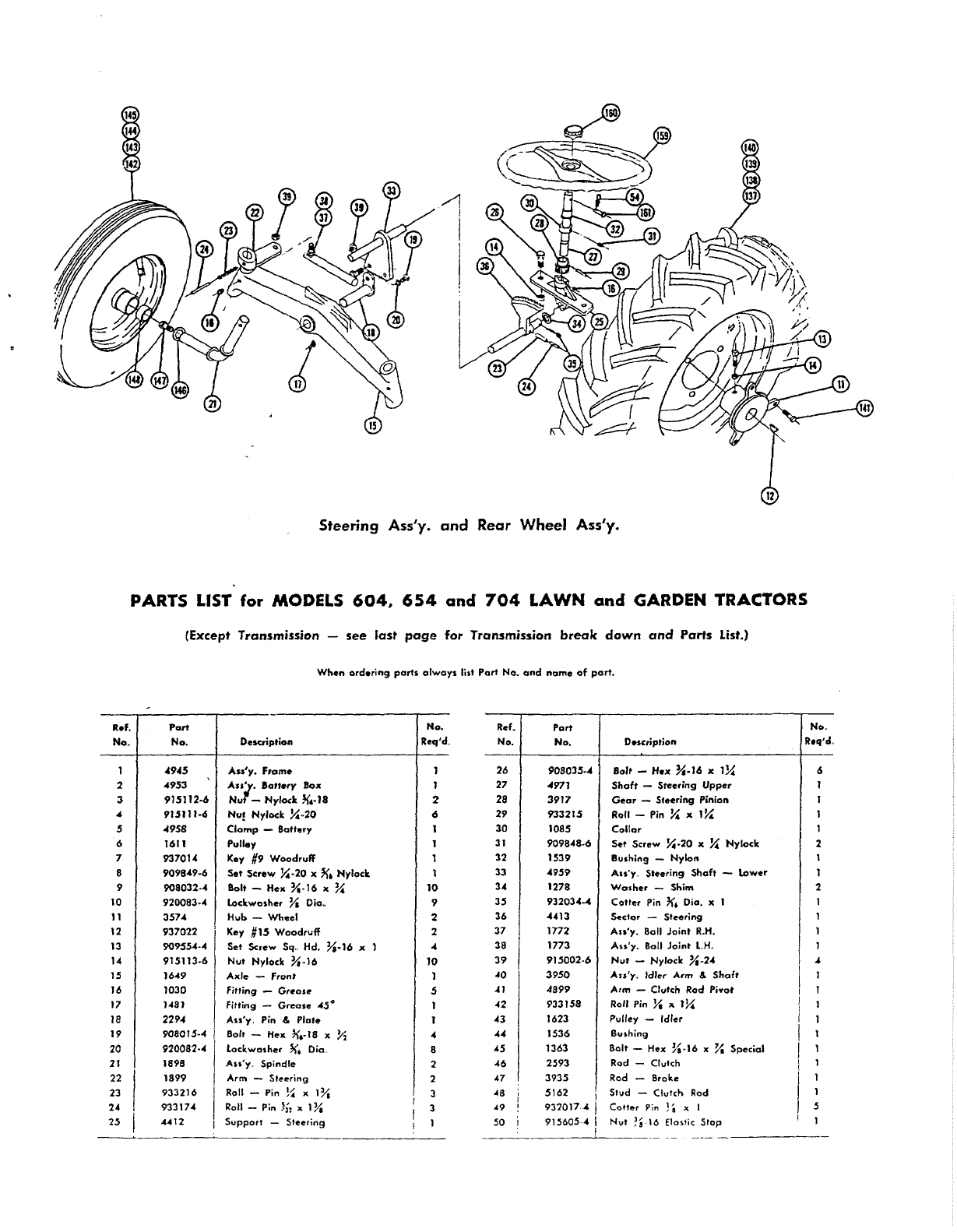
Steering
Ass'y.
and
Rear
Wheel
Ass'y.
PARTS LIST
for
MODELS
604,
654
and
704
LAWN
and GARDEN TRACTORS
(Except
Transmission
-
see
last
page
for
Transmission
break
down
and
Parts
List.)
When
ord.ring
paris
always
li,t
Pari
No.
and
name
of
part.
----~------~----------------------.---
Part
No.
4945
4953
915112·6
915111.6
4958
1611
93701"
909849·6
908032·"
920083,,4
3574
937027
909554·4
915113·6
1649
1030
H8)
22114
908015·4
920082·4
1898
1899
933216
933174
4~12
Description
Ass'y.
Frame
A
..
'.1.
!oll.ry
Box
Nur
-
Nylod:
,<,.18
Nu! Nylock X:,,20
Clamp
-Battery
PuU.y
Key
#9
Woodruff
S.t
Screw
x:
,,20 X
~.
Nylock
Bolt -
Hex
X·16
"
~
lockwosher
Ya
Oio"
Hub
-
Wheel
Key
#15
Woodruff
Set
Screw
Sq
..
Hd. Ya.16 "
Nut
Nylock
X·,16
A"I"
-Front
Fitting -
Grea.e
Fitting -
Grease
4,s°
Au'y,
Pin &
Plale
Bolt -
H""
k'
•.
18 x
Y,
lock
washer
k'.
Dia.
Au'y
..
Spindle
Arm
-
Steering
Roll -Pin
!~
"
IYa
Roll
-Pin
)32
" lYa
Support
-
Steering
No.
Req'd.
I
Z
6
10
9
2
2
01
10
I
S
4
8
2
2
3
Ref..
No.
26
27
28
29
30
31
32
33
34
35
36
37
38
39
~O
~I
~2
43
44
"S
016
~7
48
49
50
Part
No.
908035,,4
4971
3917
933215
1085
909848·6
1539
4959
1278
932034"'"
""13
1772
1773
915002
..
6
3950
4899
933158
1623
1536
1363
2593
Bolt -
Hex
M·Il>
" IX:
Shaft
-
Steering
Upper
Gear -Sfeering Pinion
Roll -Pin
x:
"
1l{
Collar
Set
Screw
V.
.20
"
x:
Nylock
Bushing -Nylon
Au'y.. Steering
Shaft
-
lower
Wa.her
-Shim
Cotter
Pin
'<.
Die. " 1
Sector -
Steering
Au'y.
8011
Joint
R.H.
Au'y
..
8011
Joint
l.H
..
Nut
-Nylock
Ya,,24
Au'y
..
Idl~r
Arm &
Shafl
Arm -CIvIc" Rod Pivot
Roll Pin
Yt
" IV.
Pulley -Idler
B<uhing
Bolt
.-
Hex
K,16
x
Va
Special
Rod -Clulch
3935
Rod -Broke
5162
I
Stud
-Clutch Rod
932017.'"
Cotler
Pin
).
" I
9156054
I
Nul;~
·16 Ela,'ic
Stop
______
.-L
__
._
._
No.,
Req'd.
6
1
2
2
"
I
1

R.f.
No.
51
52
53
54
55
56
57
58
,
59
60
61
62
63
64
65
66
67
68
69
70
71
72
73
7.4
7.5
76
77
78
79
80
81
82
83
a.4
85
86
87
88
89
90
91
92
93
94
95
96
97
98
99
100
101
102
103
10.4
105
106
107
108
109
110
PARTS LIST for MODELS
604,
654
and
704
LAWN
and GARDEN TRACTORS
(Except Transmission -
see
last
page
for
Transmission
break
down
and
Parts
list.)
Port
No.
1129
4417
2267
5-52.3
4421
.4246
4239
1014
3933
933188
2266
4438
4439
933168
3624
3578
3680
1000
5-52
..
6
2274
2179
2196
3931
932120-.4
3926
3988
5-50·75
3537
908034··4
4892
1385
4993
4975
1345
1346
920081·4
2767
4962
1432
909082··4
4419
3973
900113.4
915115·6
4972
4973
4895
4980
4981
5150
4416
1739
1754
4985
1755
1756
2297
1240
4943
4218
Wh.n
ord
...
ing
part.
olways
lill
ParI
Ho.
and
name
of
part.
D.scription
Spring
-Clulch
Ass'y.
l....
"r
& Knob -Brake
Pedal
-Clutch
Hairpin -
Cott.r
Fool,..,
Ass'y.
Trip l.....r (654.704)
P.dol
-
Altach
..
Clutch (654.704)
Spring
(654
..
704)
link
(654.704)
Roll Pin
K,
" I (654.704)
Au'y.
Lift
Le
....r
Plunger
Rod
Roll' Pin
~
x lK.
Spring
Guid.
-Rod
Cop
Grip
-
Handle
Hairpin
-
Colter
Quadranl
Rod -
Height
Conlrol
Knob
-Height
Control
Au'y..
Coble
.-
Lift
.
Clevi.
!{
Dia.
Hitch
Pin -Hitch
Shaft
Snap
Ring ~
Shoft
Spring
-
Sea'
IIQlt
-
Hu
K·16
x
A
..
'y
..
Tool
So><
Screw
'-
SemI
!{:.20 "
V,
Ass'y.
S.1t
Guard
(704)
A
..
'y.
Hood -
Complete
Thumb
-
Screw
K·20
)(
Y.
Thumb
-Screw X
.20
x
~
lockwa.her
Y.
Dio.
Grommet
2Y, 1.0.
Al:'y
..
Belt
Guord
(604.654)
Screw
-
Rd..
Hd.
~
...
24
" Y,
Screw
Rd. Hd
..
%
..
16 x
Y,
Shield
Sea,
Bolf -
Carriage
~~
..
13
x IV.
Nut
-Nylcck
Y,
..
ll
fender
R
..
H
..
fender
l
..
H
..
Ass'y.
Cover
Ass'y.. Engine - 6 H
P..
(604)
A
..
'y
..
Engine
-.
6 H
.P..
(654)
Ass'y.
Engine - 7 H
P.
(704)
8ase
.-
Engine (604·654)
Mume'
(604·654)
Nipple
~
Pipe x
5!1
(604-654)
D..cal -
In.trument
Panel
No.
Req'd.
4
2
1
2
1
2
2
1
2
18
1
2
3
1
3
Elbow
~
Pipe
x
90'
Street
EI
(60
....
654)
1
Nul
lock
~
Pipe (604.654) 1
Brace
-Exhaust (604
..
654)
"U"
Bolt
(604.654)
Nipple
-
~~
Pipe ,. 4 (60,(
..
654)
Nipple
-
y.
Pipe
x 1
!.~
(604·654)
Ref.
No.
III
112
113
114
115
116
117
118
119
l20
121
122
123
124
125
126
127
128
129
130
131
132
133
134
13S
136
137
138
Il9
140
141
142
1-13
144
145
146
147
148
149
ISO
151
152
ISJ
154
155
156
157
158
159
160
161
162
163
164
165
166
167
168
169
170
Port
No.
4216
4217
5222
5223
5224
1621
13.49
17«
3947
3939
943366-·4
2676
5186
4941
908019·4
..
897
950141
..
4
1796
5171
5170
1364
920127
..
4
2879
909000
..
4
915562·'"
920078
..
4
1667
1700
1662
1654
1004
1709
1712
1656
1657
28«
908033
..
6
2816
4987
4882
.4881
3668
3279
4856
3757
3653
4979
908002
..
4
4983
2897
9329,(8
..
4-
1813
1576
5
..
56
..
6
3978
5147
4969
4970
4410
4984
D.scription
!lbGw -X Pip.
It
90°
(604-65-4)
Cop
X
Pi~
(604-654)
Elbow -
90°
Specio'
(704)
Nipple
~
Pipe
It
4 - Special (704)
Cap
-
Yo
Pi~
(704)
pun.y
-
Engine
I<ey
y.
It
X
It
l}~
Muffl.r
(704)
Nipple
I"
Cia
..
Pi~
(704)
Elbow
I"
It
45" (704)
Nippl.
I"
Pipe
It
2"
(704)
Ass'y. Fuel Tonic
Cap
-Fuel
Tonk
Valve
-
fuel
Shut
011'
& Filter
80lt
-
Hex
K.·18
It
1
Speed
Nut
~,.18
Clamp
K.
Oio
..
Corbin
(704)
fuel
Line (704)
Au'y..
Control
-Throttle
Au'y.
Control
-
Choke
Nut
-Round
X.·18
lockwasher
J{.
Dia
..
(Ext. Toolh)
Clip
(704)
IIQlt
-
Rd
..
Hd
..
#8.32
x
Y,
(704)
Nut
-Hex
#8.32
(704)
Lockwasher
#8
(704)
Au'y.
Wheel
Tire &
Tube
.-
Rea,
Wheel
Tire
Tube
lug
-
IIQlt
Au·y
..
Wheel,
Tire & Tube -Front
Wbeel
-
With
Two 1521 Bearings
Tire
Tube-
Washer
Bolt Nylock
~"'.16
It
Ya
Hubcap
A
..
·y
..
Switch -Ignition (654)
Nut
-Hex
~~.32
-Special (654)
Lockwa.he,
Yt
Dia
..
-Special (654)
Key -Ignition (654)
Au'y.
Switch
(604.704)
Plug Button _ . .500
Hal.
(654)
Plug Button -
..
625
Hole (604
..
704)
Battery
Wiring Harness
8alt
-Hex
!{.20
x
Yt
(654)
Steering
Wheel
In,eft
p;
.. -
CI".i,
Tool Pin
"V"
Belt
Wrench
Allen
!~
Hex
Cushion
(654.704)
Decol (704)
Oecol
(654,
Decal (6{)4)
Decal -
Wh~el
Horse Emblem
Oecol -
Hood
Ponel
2
2
2
2
2
2
2
2
2
2
6
2
2
2
2
2
2
2
2
1
2

.
R.f.
..
Part
No.
No.
1
3900
2
1533
3
3915
4
1532
S
1529
6 1508
7
1528
8
1232
9 1303
10
3503
11
3515
12
3516
13
933156
14
3517
15
3518
16
3573
17
3522
18
1518
19 3907
20
$-·50··75
21
3523
22
352-C
23
3526
24
3910
25
937014
26
3525
'17
1504
28
3128
29
3527
30
4204
31
1516
j
[
32
3909 I
Transmission
TRANSMISSION
PARTS
LIST
When
ord.ring
ports
alway.
li.t
Part
No.
and
nom.
of
port
•
No
..
R.f.
o..cription
Req'd.,
No.
COlO
• T
ransmiuion
1
33
IHc"ing
• Boll I
34
Pin
locating
2
35
Beo,ing
•
Needle
1
36
a.ct."ing •
Needle
2
37
Bea,ing
•
Needle
2
38
Bearing
•
Needl.
2
39
Seal·
Oil
3
40
Seal·
Oil
I 41
fork.
Shift
2
42
Roil
..
',ont
Shiff
1
43
Roil·
Rear
Shifl
I 44
Pin • Roll
y.
,.
1 2
45
BolI.Stop
2
46
Spring.
Stop
, ,(7
Shift
Pin.
Stop
1
48
Gear·
Input
O,i
••
1
49
Bearing.
Needle
I
50
Shaft·
Splino
I 51
Snap
Ring T
ruorc
~
Shaft
I
52
Gear
(Hi & Intor.) 1
53
Gear
(low
&
Reve"e)
1
54
Gear
•
Spline
Shaft
I
55
Clu.t",
•
Shaft
1 56
Koy
•
#9
Woodruff
2
57
G""r
..
Cluller
I
58
8u.shin9
..
8,on:e> I 2
59
Pinion
..
Cluster
Shaft
Reduclion
I 1
60
Gear.
Clu,'er
Shaft
Reduction 1
61
GeD'
..
Reve,ut
IdJ",. I I
62
Bushing
...
Bronte
I I
63
I
Pi"
..
Reverse
Idler
5 I
Part
No.
3903
3906
3905
3904
3908
933217
4235
1329
1316
3912
3901
1530
1531
943460
..
4
9.013420·.01
908038·4
908043·4
915113
..
6
4898
3514
933168
909854
..
4
915111
.....
3577
1001
3902
937022
5-50
..
100
«37
908002·4
noon·'
D.lcription
N
....
lIeq'd.
.-------f-.
Gear·
Brake
Shaft
1
Gea,
~
Bull 1
Cal
••
Diff.,.
nlial
2
A,,1e •
Rear
Gear.
Axl.
Pi"
• Roll ~
2
2
"I~
2
Gear
•
Diff.r.
ntial
Pinion 4
Cap
Screw.
H."
JJ',
-18
J(
3X
4
Nut·
H.,.
..
toe
kK
•.
II
4
Ga.ket
1
CQ,S.
rron.mi.
tion 1
Bearing·
N
••
dl.
I
!Haring.
N
...
d
~
1
Y.
S,d.
Pipe
Yo
Std.
Pip.
Bolt.
Hex • l
Plug
I
"ug
1
Yo
..
16
" 2 5
80lt
..
H.,,,
.)
Yo
• 16 " 3)1 1
Nut·
Nylock
Yo.
16 6
Slick.
Shift
Collar
..
Shift
1
1
,.
'~
I
Pin.
Roll
~2
Screw
• Soc., Hd
.•
Sel
Yo
•
20
"
~~
1
Nul.
Hu
Lac
k X .
20
1
800t
..
Shift
to
...
er
1
Knob.
Shift
Drum _
B,ak.
K.y
#1$
Woo
Snap
Ring 1 •
lIand
..
S.oko
Boh •
He-I(
!~
druff
Sho(t
20
)(
~~
Wo,hel"
..
lode
1
I
2
2
8·963
Form
No
..
163
..
164
..
165
This manual suits for next models
2
Table of contents
Popular Tractor manuals by other brands


 Operator's manual")


Egimotors
Egimotors RZR XP CREW 1000 owner's manual

Jodale Perry Corporation
Jodale Perry Corporation Jacobsen HR9016 Mounting instructions

New Holland
New Holland Boomer 1020/T1010 Specifications

Ingersoll
Ingersoll 226 manual

Bercomac
Bercomac 700279-3 owner's manual

Simplicity
Simplicity Sovereign 3416H owner's manual


