Ingersoll 226 User manual

?it->
",/ 'i,,
vngersoil
ELECTRICAL SYSTEM
: MoDEL 226, 446, 449,646, 649
Service Manual No. 9-51721
i
QUALITY IN THE AIIER.ICAN TR,ADIT(XJ
Winneconne, Wisconsin 54986-9576
e
lngersoll Equipment Co., lnc.
Garden
Tractor
Talk
Digitally signed by Garden
Tractor Talk
DN: cn=Garden Tractor Talk,
o=GTtalk.com, ou,
c=US
Date: 2011.10.16 12:05:00
-04'00'
TABLE OF CONTENTS
SafetyMessages ........3
lntroduction .... ..4
TestEquipment... ......4
\Mring Diagrams .. .. ..$g
Troubleshooting Chart .. . ..10-12
BatteryCareand Maintenance .....13-16
BatteryCheckSheet. .....16
Starter Motor Repair .17-24
For Models 226, re,4r18,ffi .17-'tg
For Model646. .. .... ..20-24
FlywheelAlternator .....25
lgnition ......25-25
BreakerPointsService ....25
lgnitionTiming Procedure .......26
CoilService .......n
CondenserService .......21
Spark Plug ... . .. . .29
\,
Printed in U.S.A. -2- 9-91-RP-500-165
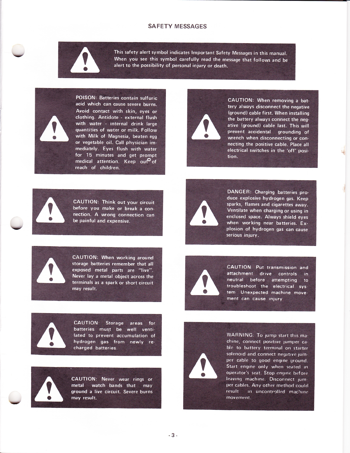
SAFETY MESSAGES
v
-3.
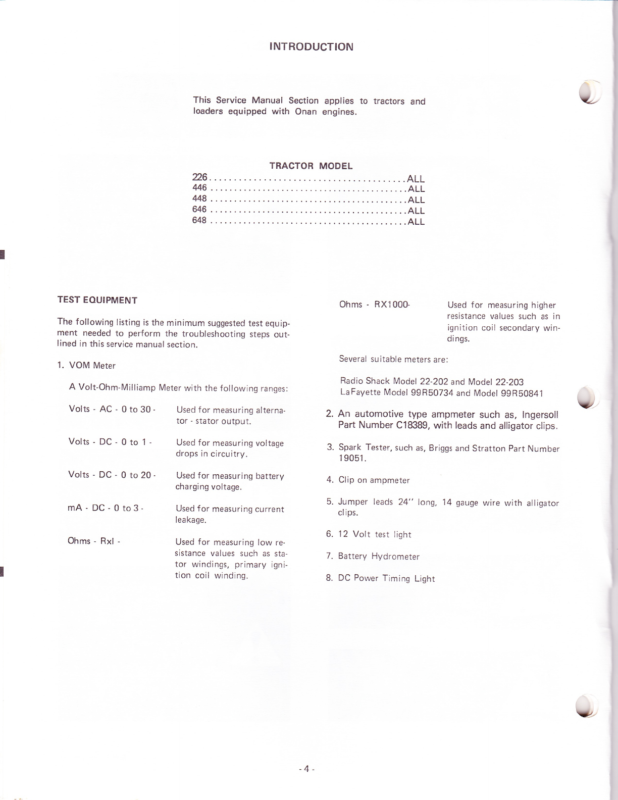
INTRODUCTION
This Service Manual Section applies to tractors and
loaders equipped with Onan engines.
TRACTOR MODEL
26... .......A11
446... ....ALL
uB ... ....ALL
646 .. . ... .ALL
648 . .. ....ALL
TEST EOUIPMENT
The following listing is the minimum suggested test equip-
ment needed to perform the troubleshooting steps out-
lined in this service manual section.
1. VOM Meter
A Volt-Ohm-Milliamp Meter with the following ranges:
Volts - AC - 0 to 30 - Used for measuring alterna-
Volts-DC-0to1-
tor - stator output.
Used for measuring voltage
drops in circuitry.
Volts - DC - 0 to 20 - Used for measuring battery
charging voltage.
Ohms - RXl00G Used for measuring higher
resistance values such as in
ignition coil secondary win-
dings.
Several suitable meters are:
Radio Shack Model22-202 and Model 2Z-2O3
LaFayette Model 99R50734 and Model g9R50841
2. An automotive type ampmeter such as, lngersoll
Part Number C18389, with leads and alligator clips.
3. Spark Tester. such as, Briggs and Stratton Part Number
1 9051.
4. Clip on ampmeter
5. Jumper leads 24" long, 14 gauge wire with alligator
clips.
6. 'l 2 Volt test light
7. Battery Hydrometer
8. DC Power Timing Light
mA-DC-0to3-
Ohms - Rxl -
Used f or measuring current
leakage.
Used for measuring low re-
sistance values such as sta-
tor windings, primary igni-
tion coil winding.
-4-
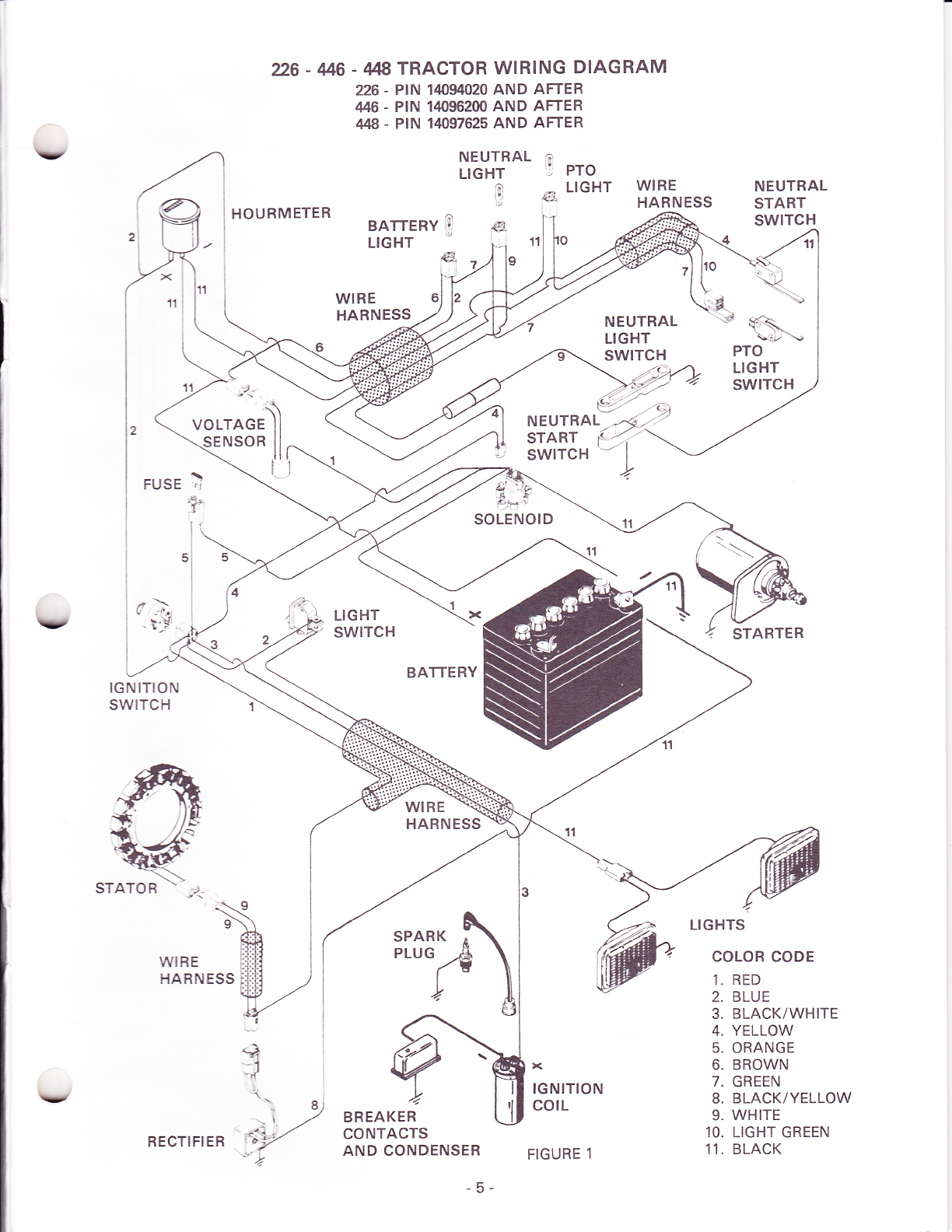
226 - M6 - 448 TRACTOR WIRING DIAGRAM
226 - PIN 140/94020 AND AFTER
446 . PIN 14096200 AND AFTER
448 - PIN 14f/97625 AND AFTER
v
\t
HOURMETER
NEUTRAL ?
LtcHT I Pro
0 s LIGHT
e,
i- 11
^la
14 .'E
,4. !
e*r
WIRE
HARNESS NEUTRAL
START
SWITCH
BAfiERY 9
LIGHT
WIRE
HARNESS s\
-sil2'-'\
FUSE
PTO
LIGHT
SWITCH
STARTER
LIGHTS
COLOR CODE
1. RED
2. BLUE
3. BLACK/WHITE
4. YELLOW
5. ORANGE
6. BROWN
7. GREEN
8. BLACK/YELLOW
9. WHITE
10. LIGHT GREEN
11. BLACK
SOLENOID
d>
- t'{'
IGNITION
SWITCH
I
WIRE
HARNESS
BATTERY
WIRE
HARNESS
BREAKER
CONTACTS
AND CONDENSER
r<
IGNITION
cotL
FIGURE 1
NEU'R^L2'2
START r('i'\
,: iviiiin 11
VY,
STATOR
Y
RECTIFIER
-5-

F
IGNITION SWITCH TERMINALS
RECTIFIER
NEUTRAL
START
SWITCH
COLOR CODE
1. BLACK/WHITE
2. RED
3. ORANGE
4. BLACK
5. YELLOW
6. DARK BLUE
7. WHITE
8. BLUE
26 - 46 - 448 TRACTOR WIRING DIAGRAM
226 _ PtN TO 14094020
446 _ PtN 9742W;3 TO 14096200
It48 _ PtN TO 14097625
NOTE: Wire from "L', terminal on switch to lights can be pink.
WIRE
HARNESS
SPARK
PLUG
BREAKER
CONTACTS IGNITION
corL
FIGURE 1A
-6-
SOLENOID
STARTER
e,1
LIGHTS
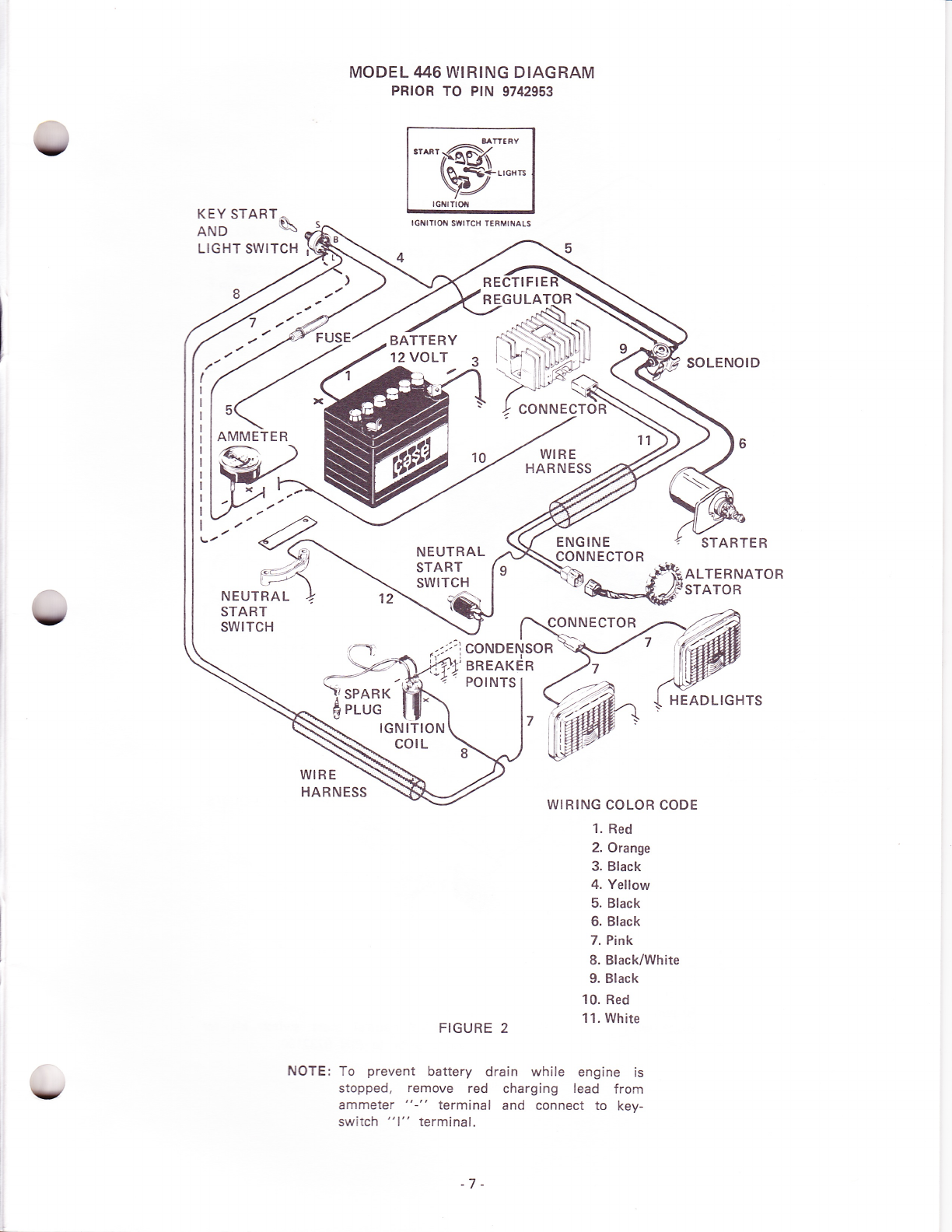
MODEL 1146 WIRING DIAGRAM
PR|OR TO PtN 9742953
Y
5
AMMETER
NEUTRAL
START
SWITCH
,r^rrl@k
v?*''o".
KEY START ^
AND \
LIGHT SWITCH
IGNITI OI{ SITI TCH TERMII{ALS
TIFIE
NEUTRAL
START
SWITCH
ENGINE
CONNECTOR
SOLENOID
STARTER
ALTERNATOR
STATOR
HEADLIGHTS
('= 1
\t :,.ICONDENSOR
-i r
,,I.t,BREAKER
POINTS
SPARK Fiih
PLUGIGNITION
corL
WIRE
HARNESS WIRING COLOR CODE
1. Red
2. Orange
3. Black
4. Yellow
5. Black
6. Black
7. Pink
8. Black/White
9. Black
10. Red
11. White
FIGURE 2
NOTE: To prevent battery drain while engine is
stopped, remove red charging lead frorn
ammeter "-" terminal and connect to key-
switch "1" terminal.
BATTERY
12 VOLT
V
-7-
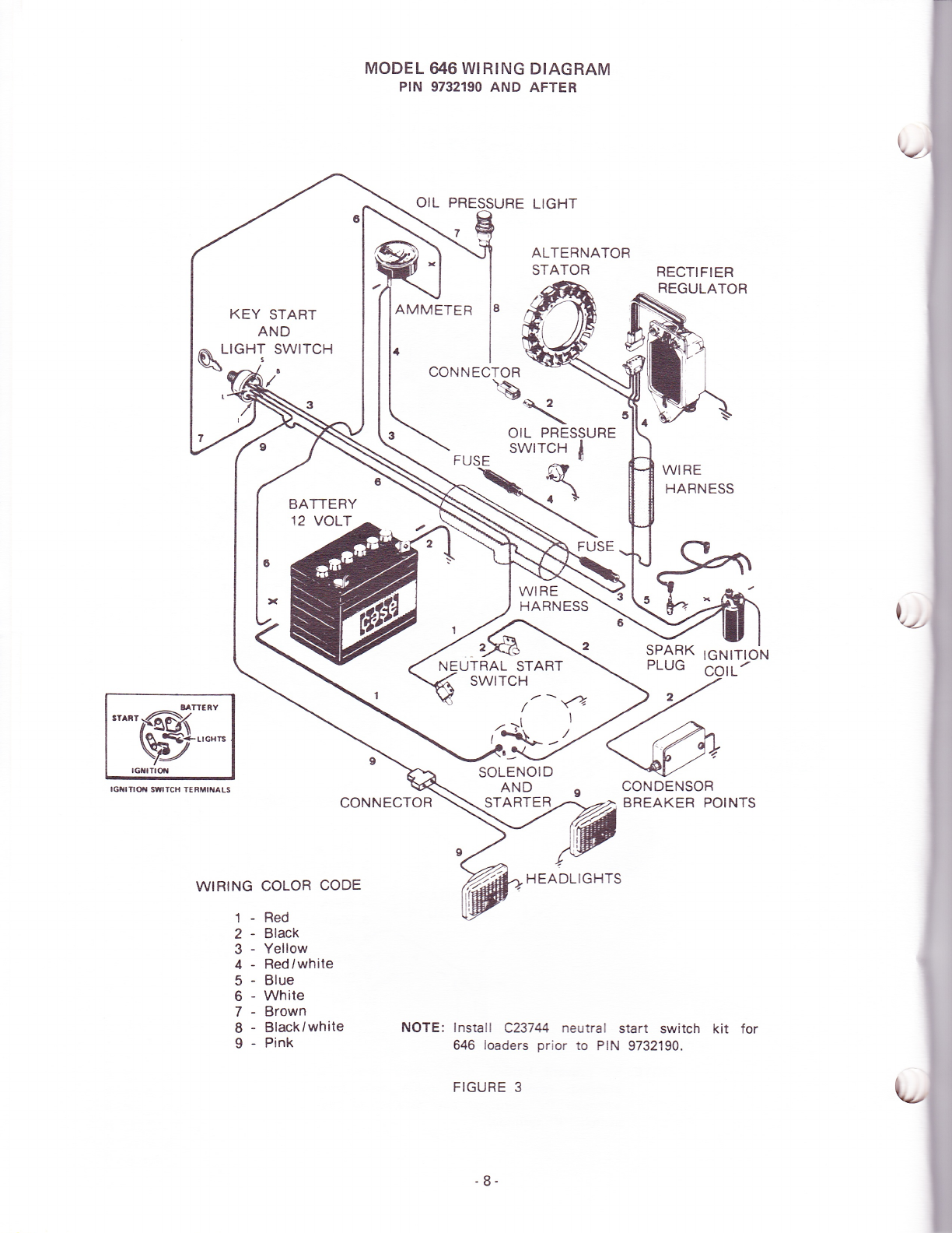
MODEL 646 WIRING DIAGRAM
PIN 9732190 AND AFTER
otL PR
7
LIGHT
ALTERNATOR
STATOR
KEY START
AND
LIGHT SWITCH
AMMETER
CONNECTOR
q*-li
WIRING
1-
2-
3-
4-
c
6-
7-
8-
9-
FUSE
"^,w:."
lclrTrof swrTcH TERiilt{aLs CONNECTOR
WIRE
HARNESS
UTRAL START
SWITCH
/t-?
SOLENOID
AND
STARTER
2
CONDENSOR
BREAKER POINTS
COLOR CODE
Red
Black
Yellow
Red/white
Blue
White
Brown
Black/white
Pink
BATTERY
12 VOLT
*\
OIL PRESSURE
swrrcH I
R
HEADLIGHTS
NOTE: lnstall C23744 neutral start switch kit for
646 loaders prior to PIN 9732190.
FIGURE 3
RECTIFIER
REGULATOR
WIRE
HARNESS
SPARK IGNITION
PLUG
;t
'1\-'-
-8-

MODEL A$ WIRING DIAGRAM
v
COLOR CODE
1. Black and White
2. Red
3. Orange
4. Blue
5. Yellow
6. White
7. Black
8. Brown
9. Dark Blue
IGNITION SWlTCH
"'@;:
IGNITIOTi SIYITCH TERMIiIALS
AMMETER
-ac---)
v
-L; -
SOLENOI D
STATO RSTARTE R
\: -l ig
3
'7
HOUR METEB
WIFI E
H ARN ESS
NEUTRAL
START
SWITCHES
BREAKE R
PO I NTS
P RESSU R E
SWITCH
'h
FIGURE 4
BATTE RY
-9-

I. ENGINE WILL NOT CRANK
SYMPTOM POSSIBLE
TROUBLESHOOTING CHART
CAUSE TEST SOLUTION
A. Solenoid doesn't click or
clicks repeatedly (See "B"
below)
1. Dead or weak battery Hydrometer test. Voltmeter
reading 9.5 minimum at bat-
tery terminals when cranking
Charge or replace battery
2. Poor or open connection at
solenoid, ampmeter, f use,
key switch, or neutral start
switches
Visually inspect Clean and tighten loose or
corroded connections
B. Solenoid doesn't click 1. One or both neutral start
switches oPen All models except 646 PIN
9732190 and after:
Connect jumper wire f rom
solenoid post (Small post
ground side) to ground. Turn
key to start.
646 PIN 9732190 and after:
Brief ly touch wire from batte-
rY "+" terminal to starter
solenoid spade terminal.
Disengage PTO clutch and pul
travel lever in N. Repair or
replace one or both N start
switches if defective
2. Fuse blown Check continuity Replace fuse
3. Open ampmeter Check continuity Replace ampmeter
4. Open solenoid Check continuity Replace solenoid
5. Open ignition switch Connect iumper from batterY
positive to solenoid "+" small
terminal or from B to S ter-
minal on switch
Replace ignition switch
C. Solenoid click but engine
won't crank (See A above) 1. Engine tight Attempt to turn engine man-
ually to check for free rotation Repair engine if found to be
tight
2. Defective solenoid switch Connect heavy jumper wire
across large solenoid posts.
Engine should crank.
Replace solenoid
3. Defective or worn starter Repair or replace. See starter
motor section of this manual.
II. ENGINE CRANKS IN GEAR
*646 PIN 9732190 and after
pedal depressed or PTO "on"
or shorted N-Start switches.
cranking with travel
indicates misadjusted
A. Engine cranks with travel
lever in drive (600 series -
travel pedal depressed)
Grounded N start switch (tra-
vel or PTO) or wire lead Visual inspection. Disconnect
wire from small solenoid post
to PTO N-Start switch.*
Repair or replace wire lead or
N - Start switch {travel or
PTO).
B. Engine cranks with PTO
clutch in gear or both
travel and PTO in gear.
Grounded PTO N Start
switch or wire lead or
grounded starter solenoid
Visual inspection. Disconnect
wire from small solenoid posts
N - Start switch. Attempt to
crank engine.*
Repair or replace lead or N -
Start switch. lf unit cranks
with wire disconnected - R &
R solenoid.
-10-

III. ENGINE CRANKS.
SYMPTOM BUT WON'T START
POSSIBLE CAUSE TEST SOLUTION
v
v
IV. ENGINE RUNS ERRATICALLY
V. BATTERY UNDER CHARGING (OR NO CHARGE)
*NOTE: Be sure to check all connections for con_
tinuity before replacing major components. Be sure
rectifier regulator is grounded to tractor frame.
ITNOTE: Stator output voltage between 14 and 2g
volts AC is adequate to charge battery at reduced
rate. Reciuced stator output could be caused by dirt
accumulations or weak f lywheel magnets. Remove
flywheel, inspect and correct as necessary.
A. Engire c:a:ks s a#.y and
won': s:a-: Erec:ri*t pr.o-
Dle:ns cr v
See A. & C. above
B. Engire cranks but
s'€.: li9 spark) won't 1. Points not opening and
closing Check gap Clean and set gap. Time en-
gine. Refer to specifications
for correct point gap.
2. No (low) voltage to coil Check for battery voltage at
coil + with voltmeter or test-
ing light. Hold switch in
"start" position.
Check wire connections and
ignition switch continuity from
"8" to "1" in both start and
run positions
Replace switch or wires as
requ i red.
646 prior to plN 9732190: ex-
cessive voltage drops at star-
ter solenoid. lnstall C23744 N_
start switch.
3. Spark plug lnspect for grounded high
tension lead or cracked insu-
lator or fouled spark plug
Repair or replace lead or plug
as required
4. Defective ignition coil Use coil tester Replace
5. Shorted to ground conden-
ser Unhook condenser lead. Crank
engine. lf weak spark is now
seen, condenser was shorted.
Replace condenser
A. Engine runs at idle and
erratically (electrical pro-
blems only). Flashing blue
arc at points. Points
bu rned.
Faulty condenser or condenser
connected to coil "+" (points
and condenser should be con-
nected to coil "-")
Condenser test. I nspect con-
nection. Replace or connect condenser
to coil "-".
A. Battery goes dead with
normal usage 1. Defective battery
2. Cold weather, short running
periods
3. Stop start operation Keep engine speed high
enough to charge
4. Dirty or corroded terminals
or wires
5. Excessive electrical loads Total individual loads Reduce total load
No charge to battery (amp-
meter at .0) Battery fully charged Turn head lights on for 5
minutes with engine shut off.
Start tractor.
Ampmeter shows charge. ln-
dicates charging system func_
tioning properly.
Defective rectifier, regulator or
stator- Run engine at 3600 RpM for
3 - 5 minutes. Measure D-C
volts at battery terminal
lf 13.6 volts charging system
okay, check for faulty amp-
meter or fully charged batte-
ry. lf less than ,l3.6 volts,
test stator output.
Run engine at 3600 RpM.
Measure AC volts at slator
output plug* {unplug from
rectifier regulator)
lf less than 28 VAC replace
statort. Retest rectifier regu-
lator. lf more than 28 VAC,
stator okay, replace rectifier
regu lator.
- 11 -
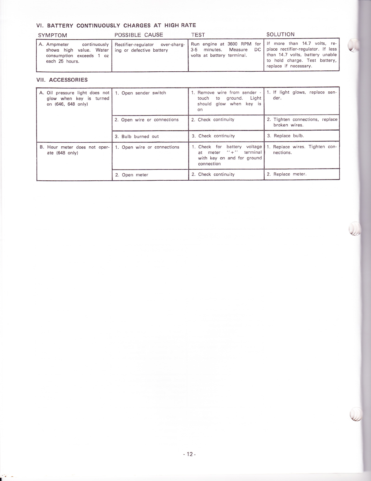
VI. BATTERY CONTINUOUSLY CHARGES AT
SYMPTOM POSSIBLE CAUSE
HIGH RATE
TEST SOLUTION
A. Ampmeter continuously
shows high value. Water
consumption exceeds 1 oz
each 25 hours.
Rectifier-regulator over-charg-
ing or defective battery Run engine at 3600 RPM for
3-5 minutes. Measure DC
volts at battery terminal,
lf more than 14.7 volts, re-
place rectifier-regulator. lf less
than 14.7 volts, battery unable
to hold charge. Test battery,
replace if necessary.
vll. AccEssoRtEs
A. Oil pressure light does not
glow when key is turned
on (646, 648 only)
1. Open sender switch l. Remove wire from sender -
touch to ground. Light
should glow when key is
on
l. lf light glows, replace sen-
der.
2. Open wire or connections 2. Check continuity 2. Tighten connections, replace
broken wires.
3. Bulb burned out 3. Check continuity 3. Replace bulb.
B. Hour meter does not oper-
ate (il8 only) 1. Open wire or connections 1. Check for battery voltage
at meter "+" tetminal
with key on and for ground
connection
1. Replace wires. Tighten con-
nections.
2. Open meter 2. Check continuity 2. Replace meter.
I
12-
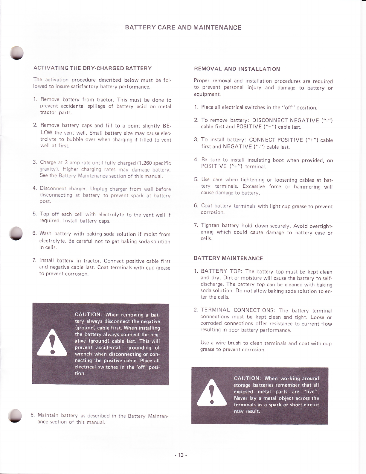
ACTIVATI NG THE DRY.CHARGED BATTE RY
The activation procedure described below must be fol-
lowed to insure satisfactory battery perf ormance.
1. Remove battery from tractor. This must be done to
prevent accidental spillage of battery acid on metal
tractor parts.
2. Remove battery caps and f ill to a point slightly BE-
LOW the vent well. Small battery size may cause elec-
trolyte to bubble over when charging if f illed to vent
well at first.
3. Charge at 3 amp rate until fully charged (1.260 specific
gravity). Higher charging rates may damage battery.
See the Battery Maintenance section of this manual.
4. Disconnect charger. Unplug charger from wall before
disconnecting at battery to prevent spark at battery
post.
5. Top off each cell with electrolyte to the vent well if
required. lnstall battery caps.
6. Wash battery with baking soda solution if moist from
electrolyte. Be careful not to get baking soda solution
in cells.
7. lnstall battery in tractor. Connect positive cable first
and negative cable last. Coat terminals with cup grease
to prevent corrosion.
8. Maintain battery as
ance section of this described in the Battery Mainten-
manual.
BATTERY CARE AND MAINTENANCE
REMOVAL AND INSTALLATION
Proper removal and installation procedures are required
to prevent personal injury and damage to battery or
equipment.
1. Place all electrical switches in the "off " position.
2. To remove battery: DISCONNECT NEGATIVE ('-"1
cable first and POSITIVE ("+") cable last.
3. To install battery: CONNECT POSITIVE ("+") cabte
f irst and NEGATIVE ("-") cable last.
4. Be sure to install insulating boot when provided, on
POSITIVE ("+") terminal.
5. Use care when tightening or loosening cables at bat-
tery terminals. Excessive force or hammering will
cause damage to battery.
6. Coat battery terminals with light cup grease to prevent
corrosi on.
7. Tighten battery hold down securely. Avoid overtight-
ening which could cause damage to battery case or
cells.
BATTERY MAINTENANCE
1. BATTERY TOP: The battery top must be kept clean
and dry. Dirt or moisture will cause the battery to self-
discharge. The battery top can be cleaned with baking
soda solution. Do not allow baking soda solution to en-
ter the cells.
2. TERMINAL CONNECTIONS: The battery terminal
connections must be kept clean and tight. Loose or
corroded connections offer resistance to current flow
resulting in poor battery performance.
Use a wire brush to clean terminals anC coat with cup
grease to prevent corrosion.
13-

3. ELECTROLYTE LEVEL: The electrolyte level must
be maintained above the cell plates at all times to avoid
permanent battery damage. The battery must be kept
filled to the vent well with water f ree of scale forming
minerals.
Water consumption in excess of 1 ounce (29 ml)
every 25 hours of operation indicates an over-
charging problem. See the testing section of this
manual.
FIGURE 5
STATE OF CHARGE: The battery must be main-
tained in a full state of charge as indicated by hydro-
meter readings. A battery that is allowed to stand in a
discharged condition will become permanently dam-
aged.
An idle battery will self discharge. For this reason, idle
batteries should be checked periodically and charged
as necessary.
Discharged batteries will freeze in cold weather. For
example, a battery with specific gravity of 1.175will
lreeze at0oF (-18oC).
CHARGING PROCEDURE:
A. Charging at a rate not to exceed 3 amps is recom-
mended.
B. Charging at higher rates up to 15 amps is permis-
sible as long as:
a. Violent gasing does not occur
b. Electrolyte is not spewed from vents
c. Electrolyte temperature does not exceed 125oF
(510C)
DO NOT exceed 15 amps charge rate.
C. A battery is fully charged when, after two, two
hour intervals at a low charge rate (3 amps), all cells
are gasing freely and no change in specific gravity
occurs.
D. Always turn charger off or unplug from wall before
removing clips from battery terminals. This prevents
arcing at battery wlrich can cause explosion of hy-
drogen gas created while charging.
BATTERY TESTING
SPECIFIC GRAVITY TEST (HYDROMETER TEST):
The hydrometer is used to measure the specific gravity
of battery electrolyte (weight of electrolyte as com-
pared to water). This indicates the state of charge of the
ba tte ry.
Mix newly added water with electrolyte before taking
hydrometer readings by:
a. charging f or 15 minutes at 3 amps and
b. applying a 75 amp load for 15 seconds (about equal
to cranking engine for 1 5 seconds).
The hydrometer reading is only correct when electrolvte
temperature is 80oF (25oC). Correct readings for temper-
ature variation in accordance with the following guide-
lines:
Electrolyte temperature correction - Fahrenheit scale
For every 1OoF below g0oF SUBTRACT .004 from
the observed hydrometer reading.
For every 10oF above 80oF ADD .004 to the observed
hydrometer reading.
Electrolyte temperature correction - Celsius scale
For every 1OoC below 2soc SUBTRACT .007 from
the observed hydrometer reading.
For every 10oC above 2boc ADD.007 to the observed
hydrometer reading.
TEMPERATURE IN 160
oF oF El.tcTROtYtt'5o
t40
rJO
t20
Io
!0o
9l
8)
70 i
50
50
4O
to
20
'O
o
4.
. " ctAvtry potNls
.28 ro ADO ot
. ze 5UIIRACT
. 20 FtoM IEADING
+ 16
at2
+8
o
-8
- t2
-,5
-?o
- 24
- ?8
- lz
ETECITOTYIE TEVII
-14-
FIGURE 6
THOTD HYDROMEIER
VEITICAI,IY STRAIGHI
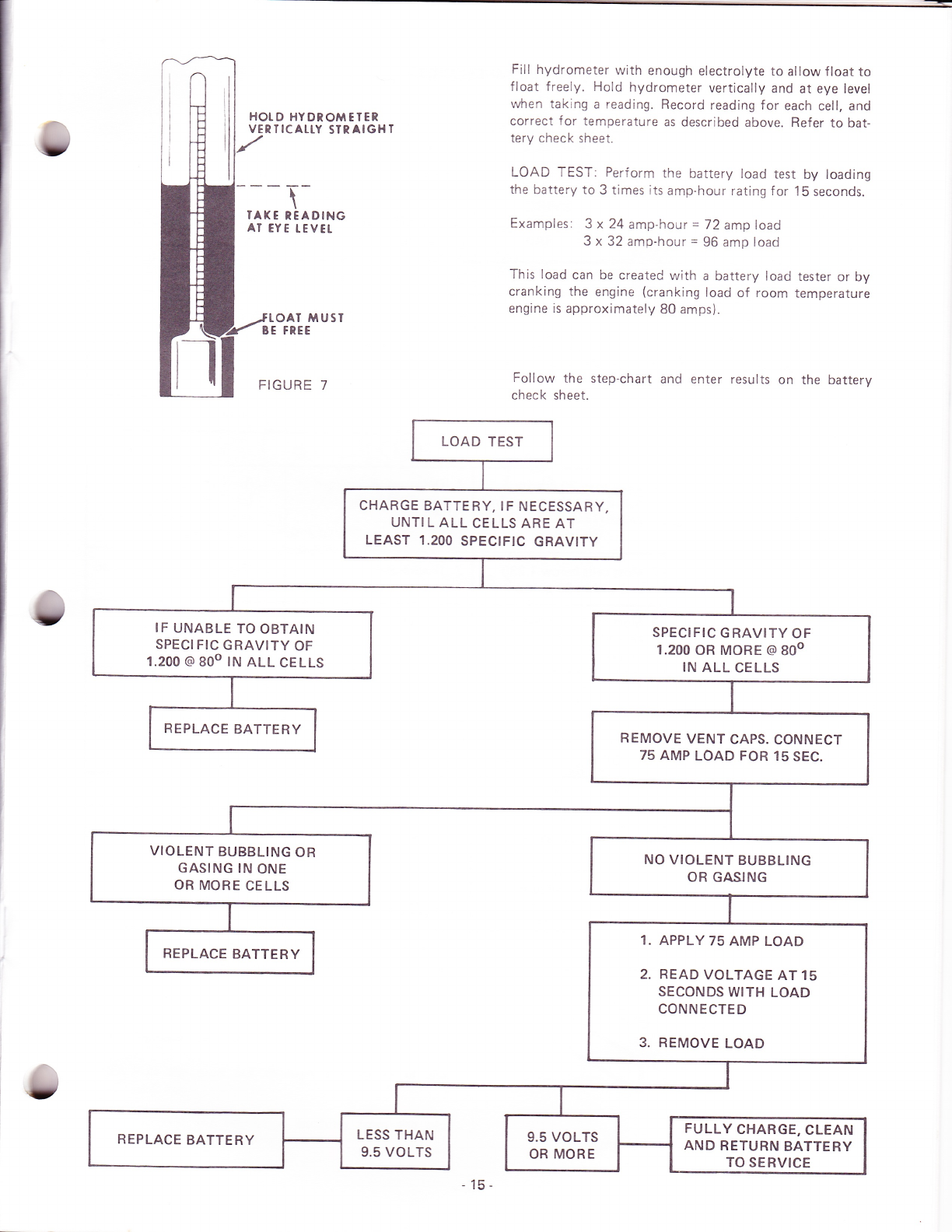
Fill hydrometer with enough electrolyte to allow f loat to
f loat freely. Hold hydrometer vertically and at eye level
when taking a reading. Record reading for each cell, and
correct for temperature as described above. Refer to bat-
tery check sheet.
LOAD TEST: Perform the battery load test by loading
the battery to 3 times its amp-hour rating for 15 seconds.
Examples: 3 x 24 amp-h our = 72 amp load
3 x 32 amp-hour = 96 amp load
This load can be createC with a battery load tester or by
cranking the engine (cranking load of room temperature
engine is approximately 80 amps).
Follow the step-chart and enter results on the battery
check sheet.
--T-\
TAX E TEADING
AT EYE TEVET
fTOAT MUSI
BE FREE
FIGURE 7
LOAD TEST
CHARGE BATTERY, IF NECESSARY,
UNTI L ALL CELLS ARE AT
LEAST 1.200 SPECIFIC GRAVITY
IF UNABLE TO OBTAIN
SPECIFIC GRAVITY OF
1.200 @ 8oo tN ALL CELLS
SPECIFIC GRAVITY OF
1.200 0R MORE @ 8oo
IN ALL CELLS
REPLACE BATTERY REMOVE VENT CAPS. CONNECT
75 AMP LOAD FOR 15 SEC.
VIOLENT BUBBLING OR
GASING IN ONE
OR MORE CELLS
NO VIOLENT BUBBLING
OR GASING
1. APPLY 75 AMP LOAD
2. READVOLTAGEATlS
SECONDS WITH LOAD
CONNECTED
3. REMOVE LOAD
REPLACE BATTERY
REPLACE BATTERY LESS THAN
9.5 VOLTS 9.5 VOLTS
OR MORE
FULLY CHARGE, CLEAN
AND RETURN BATTERY
TO SERVICE

TEST Result
VISUAL INSPECTION
Summary
BATTERY CHECK SHEET
lndication Remedy
1. Dirty battery top- Battery OK Clean
2. Clogged vents- Battery OK Clea n
3. Corrosion lf severe, possible battery
defect- Clean and continue testing.
4. Low water level- Excess water use - Test for
overcharging. Battery OK Add water
5. Cracked case- Defective battery Replace
SPECIFIC GRAVITY CHECK
Cell No. 1
Cell No. 2
'I . More than 30 gravity
points variation between
cells.
'l . Defective, discharged or
worn out batterv. 1. Recharge battery. Repeat
test. lf cell readings still
vary more than 30 points,
replace battery.
Cell No. 4
Cell No. 5
Cell No. 6
2. Most cells below 1.230
and within 30 points. 2. Discharged 2. Recharge and make Load
Test.
3. Most cells at or near f ull
charge (1.260) and within
30 points.
3. Charged 3. Make Load Test
4. Most cells above f ull
charge (1.260) 4. Overcharged 4. Check regulatcr.
NOTE: Specif ic gravity readings apply to original equipment or Case
supplied replacement batteries only. Other makes may vary.
LOAD TEST
Battery must have 1.200
specific gravity. Load e-
quals 2Ghour amp rating
x3forl5seconds
1 2 volt battery- Over 9.5 volts Battery OK Recharge if necessary
Under 9.5 volts Def ective Replace
16-
I
tl,
I
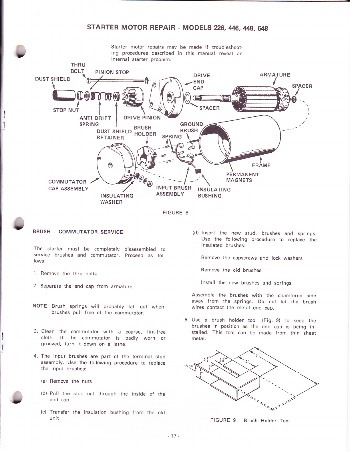
STARTER MOTOR REPAIR - MODELS 26, 4H}6, 4H/8, W
Starter motor repairs may be made if troubleshoot-
ing procedures described in this manual reveal an
internal starter problem.
THRI-'
BOLT ptN|ON STOP
\ - ";'-'- -'-' DRIVE
DUsTsHIELD \-A pf
\."-"
-rplf\_El3
Lurr r",r.o t-lYt^l- BR-usH
RP]ff?RMCIIffi
sPRTNG I ^^..^., cRouND ,4
ARMATURE
/SPACER
/
+
FRAME
r
INSULATING
BUSHING
{d) lnsert the new stud, brushes and springs.
Use the following procedure to replace the
insulated brushes:
Rernove the capscrews and lock washers
Remove the old brushes
lnstall the new brushes and springs
Assemble the brushes with the chamfered side
away f rom the springs. Do not let the brush
wires contact the metal end cap.
5. Use a brush holder tool (Fig. 9) to keep the
brushes in position as the end cap is being in-
stalled. This tool can be made from thin sheet
metal.
ilIio'i,i.*='" HoLDER sPRtNC \
Nffi-'\ PERMANENT
MAGNETS
COMMUTATOR
CAP ASSEMBLY
I
I
INSULATlNG
WASHER
BRUSH . COMMUTATOR SERVICE
The starter must be completely disassembled to
service brushes and commutator. Proceed as fol-
lows:
1. Remove the thru bolts.
2. Separate the end cap from armature.
NOTE: Brush springs will probably fall out when
brushes pull free of the commutator.
Clean the commutator with a coarse, lint-free
cloth. lf the commutator is badly worn or
grooved, turn it down on a lathe.
The input brushes are part of the terminal stud
assembly. Use the following procedure to replace
the input brushes:
(a) Remove the nuts
(b) Pull the stud out through the inside of the
end cap
(c) Transfer the insulation bushing from the old
unit
3.
4.
ASSEMBLY
FIGURE 8
/
-17-
FIGURE 9Brush Holder Tool

DRIVE ASSEMBLY
Replace drive assembly if pinion is badly worn
has broken teeth.
To remove drive assembly:
1. Hold armature shaft.
2. Remove dust shield, stop nut, pinion stop,
drift spring, and dust shield retainer.
3. Slip drive pinion off over spline and armature shaft.
Leave drive off if further disassembly of starter is
quired.
To install drive assembly:
1. Thoroughly clean the drive shaft and pinion and apply
a small amount of lubriplate AERO grease or other dry
lubricant such as graphite.
2. lnstall drive pinion, dust shield retainer, anti drift
spring, pinion stop.
3. Applv Locktite #271 to threads. Tighten stop nut to
20-25 lb. ft. (27-34 Nm). Wipe excess Locktite
from threads.
4. Push dust shield on until it snaps into position over the
shield retainer.
INSPECTION OF PARTS
TESTING ARMATURE FOR GROUNDS
Touch armature shaft or core and the end of each
commutator bar with a pair of ohmmeter leads. lf
the ohmmeter reading is low, it indicates a
grounded armature. Replace grounded armature.
TESTING ARMATURE FOR A SHORT CIRCUIT
Use a growler for locating shorts in the armature.
Put armature in growler. Hold a thin steel blade
(e.g. hacksaw blade) parallel to the core and just
above it. Slowly rotate armature in growler. A
shorted armature will cause the blade to vibrate
and be attracted to the core. Replace shorted
armature.
GROWLER
FIGURE 11 Testing Armature For Short Circuits
INSPECTING FOR AN OPEN CIRCUIT IN ARMA.
TURE
The nrost likely place to check for an open circuit
is at the commutator riser bars. lnspect for loose
connections on the points where the conductors are
joined to the commutator bars.
a nti
BRUSH INSPECTION
lf brushes are worn
mm), replace them.
move smoothlY in the
shorter than 1 /4 inch (6.35
Check to see that brushes
brush holders.
STARTER FASTENER TOROUE SPECIFICATIONS
Bolts for insulated
Terminal stud nut
Drive stop nut
brushes . . .3-3Y2 lb. ft. (4-5 Nm)
.....4-5 lb. ft. (5-7 Nm)
.. .20-25 lb. ft. (27-34 Nm)
FIGURE 10 Testing Armature For Grounds
- 18 -
Through-bolts 4Y2-6 lb. ft. (6-8 Nm)

STARTER REMOVAL
1. Remove the necessary tractor sheet metal and
accessories to enable the engine blower housing
to be removed.
0 020 i 0 0.l0" (0.51 : 0 25 mm)
FLYWHEEL GEAR FREE TRAVEL WHEN
ENGAGED WITH STARTER GEAR
MOUNTING
BOLTS
2. Remove the engine blower housing.
3. Remove the starter wire.
4. Remove the starter mounting bolts.
FLYWHEEL
RING GEAR
STARTING MOTOR
PINION GEAR
FIGUREl2 Checking Starter Gear Lash
STARTER INSTALLATION
1. Clean dirt and oil from the starter mounting
surface on both the starter and engine.
Measure the amount of free travel, or lash. be-
tween the pinion gear teeth and the ring gear
teeth, as shown in Figure 12. The proper lash
is 0.020 + 0.010 (0.51 + 0.25 mm). Loosen
and adjust the starter motor as necessary to ob-
tain the correct setting.
Tighten the starter mounting bolts.
4.
2. lnstall the starter motor and tighten the mount-
ing bolts just enough to hold the starter in its
place. 6. Connect the wire to the terminal on the starter
motor.
3. Pull the starter pinion gear outward on its shaft
so that its teeth mesh fully with those on the 7. lnstall blower housing and tractor accessories
flywheel. and sheet metal.
5.
. 19-

FIGURE 13 Starter Assembly
STARTER DISASSEMBLY
1. Loosen the M terminal nut on the magnetic
switch and remove the connector. Remove the
magnetic switch.
NOTE: The packings for the magnetic switch are
mounted so that the steel packing is located
in the front bracket side.
FIGURE 14 Magnetic Switch Removal
2. After removing the thru bolts, the starting motor
can be divided into three parts the front
bracket, housing and rear bracket.
The spacing washers shown in Figure 15 are
used for adjustment of the thrust gap of the
armature shaft. They are between the rear
bracket and the commutator.
NOTE: These washers are inserted so the steel
washer is located in the commutator side.
FIGURE I5 Removing Through Bolts
3. Remove the armature from the front bracket.
Be careful not to miss a small steel washer
used in the end of the armature shaft. Remove
the shift lever along with the armature. ln this
case, the spring holder. lever springs and re-
tainer can be taken out before the lever.
STARTER MOTOR REPAIRS _ MODEL A16
.20 -
FIGURE 16 Removing Armature
Other manuals for 226
1
This manual suits for next models
4
Other Ingersoll Tractor manuals


Popular Tractor manuals by other brands

Iran Tractor
Iran Tractor ITM 475 Operators instruction book

Simplicity
Simplicity Sovereign 499-3112H owner's manual

Cub Cadet
Cub Cadet Domestic Series 7000 Service manual

MTD
MTD 148-760 10 H.P. manual

Gravely
Gravely CONVERTIBLE 7.6 owner's manual

Briggs & Stratton
Briggs & Stratton 2690816 Setup instructions


