Southland Edger King S-WLE-1639-E User manual

Look inside for:
Page
Safety Definitions 1
Important Safety Information 2-4
Product Specifications 5
Parts & Features 5
Assembly 6
Engine Preparation 7-8
Operation 8-11
Maintenance 12-16
Technical Service 16
Troubleshooting 17
Warranty 18-21
Español 22
03/11/2008 Printed in China A101103
Operator’s Manual
Edger King
163 cc, 4 Cycle
IMPORTANT:
Thank you for purchasing this Southland™ Edger.
This manual provides complete instructions for safely operating and maintaining your Edger. Read and save these
instructions. Refer to this manual each time before using your Edger.
Record the following for future reference:
Mfg. Date Code: ______________________
Date of Purchase: Attach a copy of your sales receipt.
Consumer Toll Free Number: 1-800-737-2112
KEEP THIS MANUAL FOR FUTURE REFERENCE
MODEL No. S-WLE-1639-[E]
S-WLE-1639
If you have a question or problem...
CALL TOLL FREE: 1-800-737-2112
This product contains one or more chemicals known to the State of California to cause cancer and birth defects or other
reproductive harm. Wash hands after handling.
WARNING

Questions? Call Toll Free at 1-800-737-2112 Copyright © 2008 MAT Engine Technologies, LLC Questions? Call Toll Free at 1-800-737-2112 Copyright © 2008 MAT Engine Technologies, LLC
Oil Fill Location
Do Not Overfill
Gasoline Fill Location
Start Lever
Release lever to stop engine
Engage lever to start/run engine
Always check that the ground wires
are connected before running the unit
Push primer 3 times before starting a
cold engine. Important: Do not prime to
restart a warm engine.
Indicates WARNING, DANGER, or CAUTION.
Wear eye protection complying with ANSI
Z87.1 and hearing protection.
Read operator’s manual before operating
this machine. Failure to follow directions
could result in serious injury.
Disconnect spark plug wire when not in use
or before servicing, cleaning, or performing
maintenance on the unit.
Thrown objects. Remove all rocks, stones,
and foreign objects which could be thrown by
machine
Engine exhaust contains carbon monoxide,
an odorless and deadly gas. NEVER run unit
indoors or in a poorly ventilated area.
Do not use if children or bystanders are
present.
Do NOT touch hot muffler or cylinder.
These parts are extremely hot from opera-
tion and may remain hot for a short time
after operation.
Rotating parts can cause serious injury. Keep
hands and feet away.
To reduce risk of fire, clean spilled gas and
oil and keep unit free from debris. Gasoline is
extremely flammable. Allow machine to cool
before refueling.
Safety Definitions
• Save these instructions
Safety Warning Symbols
Control and Operating Symbols
Indicates an imminently hazardous situation which, if not avoided, will result in death or serious injury.
Indicates a potentially hazardous situation which, if not avoided, could result in death or serious injury.
Indicates a potentially hazardous situation which, if not avoided, may result in minor/moderate injury or
equipment/property damage.
DANGER
CAUTION
WARNING
The following symbols are used on the product and in this manual to alert the operator of potential safety hazards. Read
them carefully, and understand their meaning.
Safety Alert Symbols
The following symbols can be found on your edger. Carefully read and understand their meaning.
INCREASE
CUTTING
DEPTH
STA RT
ENGINE
STOP
START /
RUN
WIRES MUST BE
CONNECTED
DANGER
RESPONSIBILITY OF OPERATOR
1. Carefully read and follow these safety instructions. Failure to do so can result in serious injury.
2.
Know your product. Read and understand this manual before use. Compare the illustrations to unit. Learn location
and function of all controls. Thoroughly understanding the unit before use will result in the best performance and safety.
3. Follow all instructions when assembling the unit. If the unit was purchased in assembled condition, the operator must
check the unit carefully to make sure it was assembled according the instructions in the manual before use.
4. Regularly inspect the edger. Make sure parts are not bent, damaged, or loose.
5. Use this equipment for its intended purpose only.
6. Operate the unit only with guards, shields, and other safety items in place and working correctly.
7. Service the unit only with authorized or approved replacement parts.
8. Complete all unit maintenance and adjustments according to the instruction in this manual.
WARNING
Look for this symbol to point out important safety precautions. It means: “ Attention! Become Alert! Your Safety Is
Involved.”
WARNING
Engine Exhaust, some of its constituents, and certain vehicle components contain or emit chemicals known to the State
of California to cause cancer and birth defects or other reproductive harm.
WARNING
To prevent accidental starting when setting up, transporting, adjusting or making repairs, always disconnect spark plug
wire and put wire where it cannot contact the spark plug.
PREPARATION SAFETY
WARNING
•Read, understand, and follow all instructions on the machine and in this manual. Be thoroughly familiar with the
controls and the proper use of the edger before starting. Know how to stop the engine quickly.
•Familiarize yourself with all the safety and operating decals on this equipment.
WARNING
•Thoroughly inspect the area where the edger is to be used and remove all foreign objects. Your equipment can propel
small objects at high speed causing personal injury or property damage. Stay away from breakable objects, such as
house windows, auto glass, greenhouses, etc.
•Check that all nuts and bolts are tight and equipment is in good condition.
WARNING
•Always check that the flameout wire is connected before starting engine.
OPERATION SAFETY
•Never allow children or young teenagers to operate the edger.
WARNING
•Keep area of operation clear of all bystanders, particularly small children and pets.
•Only allow responsible individuals, who are familiar with the instructions, to operate the edger.
WARNING
•Do not operate the edger while under the inuence of alcohol, drugs, or other medication which can cause drowsiness
or affect your ability to operate this machine safely.
•Do not use this machine if you are mentally or physically unable to operate the machine safely.
•Always wear ANSI compliant safety goggles or safety glasses with side shields when operating edger to protect your
eyes from foreign objects, which can be thrown from the unit.
Important Safety Information
• Save all instructions
Important Safety Information
Depth Control Lever
Move lever forward to
increase cutting depth
Start Position
PUSH TO PRIME
12

Questions? Call Toll Free at 1-800-737-2112 Copyright © 2008 MAT Engine Technologies, LLC Questions? Call Toll Free at 1-800-737-2112 Copyright © 2008 MAT Engine Technologies, LLC
Important Safety Information (Continued)
• Save all instructions
OPERATION SAFETY (Continued)
Important Safety Information (Continued)
• Save all instructions
Important Safety Information
•Wear appropriate clothing such as a long sleeved shirt or jacket. Also wear long trousers or slacks. Do NOT wear
shorts. Do NOT wear loose clothing, which could get caught in this equipment.
•Always wear work gloves and sturdy footwear such as leather work shoes or short boots. These will protect ankles and
shins from small sticks, splinters, and other ying debris, and improve traction.
•It is advisable to wear protective headgear to protect against being struck by small ying particles, or being struck by
low hanging branches, twigs, or other objects, which may be unnoticed by the operator.
WARNING
•Do not put hands or feet near or under rotating parts.
•Exercise extreme caution when operating on or crossing gravel drives, walks, or roads. Stay alert for hidden hazards or
trafc.
WARNING
•Exercise caution to avoid slipping or falling. Always be sure of your footing; keep a rm hold on the handle and walk;
never run. Never operate the edger at high transport speeds on slippery surfaces.
•Look behind and use care when backing.
•Never operate the edger without good visibility or light.
DANGER
•Do not run the engine indoors or inside a closed area. The exhaust fumes are dangerous, containing CARBON
MONOXIDE, an ODORLESS AND DEADLY GAS.
•Never leave the edger unattended when the engine is running. Stop the engine and make sure all moving parts have
stopped. Remove the wire from the spark plug.
•Do not overload the edger capacity by attempting to till too deep at too fast a rate.
•If the edger should start to vibrate abnormally, stop the engine, disconnect the spark plug wire and prevent it from
touching the spark plug. Check immediately for the cause. Vibration is generally a warning of trouble.
• Watch for holes, ruts, bumps, or other rough ground. Tall grass can hide obstacles.
FUEL SAFETY
WARNING
• Gasoline is extremely ammable, and gasoline vapors can explode if ignited. Handle with care.
•Use an approved container.
•Check fuel supply before each use, allowing space for expansion as the heat of the engine and/or sun can cause fuel
to expand.
•Fill fuel tank outdoors with extreme care. Never ll fuel tank indoors.
•Never remove gas cap or add fuel with the engine running. Allow engine to cool before refueling.
WARNING
•Do not smoke while refueling.
•After refueling, replace fuel tank cap securely and wipe up spilled fuel.
• Never store fuel or edger with fuel in the tank inside a building where fumes may reach an open ame.
STORAGE SAFETY
•
Always refer to the operator’s manual instructions for important details if the edger is to be stored for an extended period.
•Never store the edger with fuel in the fuel tank inside a building where ignition sources are present such as water
heaters, space heaters, clothes dryers, etc.
• To reduce re hazard, keep edger free of grass, leaves, or other debris build-up.
•Allow the engine to cool before storing in any enclosure.
REPAIR, MAINTENANCE, AND ADJUSTMENT SAFETY
•After striking a foreign object, stop the engine. Remove the wire from the spark plug and keep the wire away from the
plug to prevent accidental starting. Thoroughly inspect the edger for any damage. If damaged, have the
equipment repaired by a trained technician before restarting and operating.
WARNING
•Stop the engine before cleaning, repairing, or inspecting the unit. Make sure all moving parts have stopped. Let the
engine cool, disconnect the spark plug wire and move it away from the spark plug.
• Never attempt to make any adjustments while the engine is running except when specically recommended by the
manufacturer.
•Keep the edger in safe working condition. Check all fasteners at frequent intervals for proper tightness.
• When servicing or repairing the edger, do not tip the machine over or up unless specically instructed to do so in this
Manual. Service and repair procedures can be done with the edger in an upright position. Some procedures will be
easier if the machine is lifted on a raised platform or working surface.
•Use only original equipment or authorized replacement parts.
WARNING
•Never tamper with safety devices. Check their proper operation regularly.
•Do not change the engine governor setting or over-speed engine.
•Clean and replace safety and instruction decals as necessary.
• To guard against engine over-heating, always have engine debris lter mounted and clean.
CHILDREN SAFETY
WARNING
•Tragic accidents can occur if the operator is not alert to the presence of children. Children are often attracted to the
edger and the edging activity.
•Keep children out of the edging area and under the watchful care of a responsible adult.
•Never assume that children will remain where you last saw them.
•Be alert and turn edger off if children enter the area.
•Before and while moving backwards, look behind and down for small children.
•Never allow children to operate the edger.
•Use extra care when operating near blind corners, shrubs, trees, or other objects that may obstruct vision.
34

Questions? Call Toll Free at 1-800-737-2112 Copyright © 2008 MAT Engine Technologies, LLC Questions? Call Toll Free at 1-800-737-2112 Copyright © 2008 MAT Engine Technologies, LLC
Edger Specifications
• Save all instructions
Parts & Features
Unit Weight............................71 lb. (32kg)
Cutting Depths ................... 0-3.0 in. (0-76 mm)
Blade Diameter................ 9 in. (228 mm), 3 point
Gasoline Type ..... Regular Unleaded / 88 Octane (min.)
Gasoline Capacity ..................... 3.5 qt. (3.3L)
Oil Type (API SG-SL) 10W-30 is recommended for all ser-
vice temperatures. See page 7 for additional information.
Oil Capacity ......................... 19 oz (562 ml)
Spark Plug Model...................... Torch F7RTC
1. Start Lever Lever on handle which allows the engine to
run. When lever is released, engine will stop.
2. Primer Bulb Injects fuel mixture into the carburetor for
cold starting the engine.
3. Muffler Location of engine exhaust.
4. Adjustable Rear Wheel
Right rear wheel is adjustable to
level the edger when edging along a curb (curb-hopping).
5. Adjustable Front Wheels Front wheels are adjustable from
side to side for balance. The front wheels can also adjust
down for curb-hopping.
6. Recoil Starter Handle The engine is equipped with an
easy pull recoil starter.
7. Index Lever Permits adjusting the cutting angle to 15
degrees, 0 degrees (vertical), or -15 degrees. To change
the angle, pull the index lever and rotate the quill assembly
to the desired angle.
8. Blade Rotating cutting element.
9. Blade Guard Prevents stones and debris from being
thrown at the operator.
10. Spark Plug/Spark Plug Wire
Provides spark to ignite air/
fuel mixture. The Spark Plug Wire must be disconnected and
moved away from the Spark Plug when servicing the unit.
11. Air Filter Removes debris and contaminates from in-
take air, allowing engine to run smoothly with low exhaust.
12. Depth Selector Plate, 13. Depth Control Lever,
14. Control Rod Used to control the edging depth of cut.
15. Flameout Wire Terminals Must be connected for the
Start Lever to function.
Spark Plug Gap ...........0.028-0.031 in. (0.7-0.8 mm)
Engine Type ............. 4 Stroke, single cylinder, OHV
Displacement ............................... 163cc
RPM .................................. 3000 RPM
Torque Rating......6.5 ft-lbs gross torque per SAE J1940
Bore Diam. x Stroke............2.7X1.8 in. (68X45 mm)
Intake Valve Clearance . 0.0032-0.0047 in.(0.08-0.12 mm)
Exhaust Valve Clearance . 0.0059-0.0079 in.(0.15-0.20mm)
Angle of Ignition . . . . . . . . . . . . . . . . . . . . . . . . 25 Degrees
Read and follow the assembly instructions. Do not discard any parts or materials until the unit is assembled.
References to the right or left side of the edger are from the viewpoint of the operator’s position behind the edger.
Do not operate edger if it is damaged or not completely and correctly assembled.
Before doing any assembly or maintenance to the unit, remove the wire from the spark plug.
Always wear ANSI compliant safety glasses with side shields while assembling the edger.
Assembly
• Save all instructions
1. Assemble the upper handle to the lower handle with the
(2) pipe bolts and the (2) plastic wing nuts. Firmly hand-
tighten the wing nuts.
2. Slide one end of the control rod into the hole of the
Depth Control Lever. Secure with hairpin.
3. Slide the other end of the control rod through the hole of
the quill arm. Secure with second hairpin.
4. Attach the recoil starter handle through the rope guide,
by twisting it into position.
5. Remove the temporary insert from the engine flameout
wire terminal.
6. Connect the flameout wires from the engine and handle.
Use cable tie to secure loose wire to handle.
The following components will be found in the carton.
Quantities shown in ( ).
1. (1) Edger
2. (1) Edger Operator’s Manual
3. (1) Upper Handle
4. (1) Control Rod
5. (1) Bottle of SAE 30 Engine Oil
6. (1) Parts bag containing the following:
(2) Hair Pins
(2) Plastic Wing Nuts (M8)
(2) M8x35mm Pipe Bolts
(1) Wire Tie
(1) Spark plug socket wrench w/ rod
1. Remove all parts and packaging components.
2. Use a utility knife to cut all 4 vertical edges and lay the
side panels flat around the edger.
3. Remove any remaining packaging.
4. Roll the unit out from the carton, and place on a hard
level surface.
How to Remove Edger from Carton
A
How to Assemble the Handle
B
Flameout wires MUST be connected for correct engine
operation. Failure to connect can result in serious injury.
If you need assistance or find any parts missing, CALL
TOLL FREE: 1-800-737-2112.
NOTE: Refer to Figure 2 when following steps below:
56
WARNING
WARNING
WARNING
DANGER
WARNING
Figure 1
FRONT VIEW
Upper
Handle
Lower
Handle
Hair Pin
Control Rod
Quill Support
Arm
Hair Pin
Pipe
Bolt
Figure 2
Depth Control
Lever
Recoil
Starter
Handle
Plastic
Wing Nut
Handle
Flameout
Wire
Engine
Flameout
Wire
Connection
Terminal
Rear View
7
3
10
1
6
2
4
5
9
8
13
12
14
11
15

Questions? Call Toll Free at 1-800-737-2112 Copyright © 2008 MAT Engine Technologies, LLC Questions? Call Toll Free at 1-800-737-2112 Copyright © 2008 MAT Engine Technologies, LLC
Engine Preparation
• Save all instructions
Engine Oil
A
Engine shipped without oil. Failure to add oil will result in
serious engine damage.
A bottle of SAE 30 engine oil is included with your edger.
Refer to the chart on the right for alternative oil types to
use at different temperatures. Always use a high quality
detergent oil classified “For Service, SG, SH, SJ” or higher.
Do not use special additives.
Always use recommended oil type. Using dirty oil or
incorrect oil type such as 2-stroke engine oil will shorten
engine life.
NOTE: Engine Oil Capacity is 562 ml. For first time fill, simply
add the entire contents of the provided oil bottle to the
crankcase.
1. Place the edger on a level surface and make sure the
adjustable wheel heights are set so the main frame of the
edger is level. (See Figure 3)
2. Remove the oil ll cap/dipstick and wipe clean with cloth.
(See Figure 3)
3. Insert dipstick into ll spout but do NOT screw in.
Remove dipstick and check oil level.
4. When oil level is full, the oil will be at upper limit on dip
stick. If oil level is near or below the lower limit, oil must
be added. (See Figure 4)
5. Add oil slowly until the oil level reaches the upper limit of
the dipstick. Use a funnel or nozzle to reduce spillage.
Frequently check oil level while filling. DO NOT OVERFILL.
DO NOT UNDERFILL. Running engine at improper oil level
will seriously damage engine.
6. Replace and tighten dipstick.
7. Clean up any spilled oil.
HOW TO CHECK OIL LEVEL AND FILL TO PROPER LEVEL
Before checking oil, make sure engine is off, and spark plug wire has been disconnected from spark plug.
Engine Preparation (Continued)
• Save all instructions
Fuel
B
Operation
• Save all instructions
Before Starting the Engine
A
Before starting engine, read operator’s manual. Become familiar with location and function of all controls. Know how to
stop the engine quickly.
Before starting the engine, check that the flameout wire terminals have been connected.
• Gasoline is extremely flammable and vapors can explode if ignited. Handle with care.
Use fresh, clean, regular-unleaded gasoline with a minimum of 88 Octane.
Do NOT use leaded gasoline, gasohol, methanol, or diesel fuel. Do NOT mix oil with gasoline. Do NOT allow gasoline to
become contaminated with dust, water, or debris.
Using incorrect fuel type or contaminated fuel will cause serious engine damage.
NOTE: Fuel tank capacity is approximately 3.5 qt (3.3L)
HOW TO FILL ENGINE WITH FUEL
•Turn engine off and let engine cool for several minutes before removing the fuel cap or adding fuel.
•Never fill fuel tank indoors.
•Do not smoke while adding fuel.
Before attempting to start the engine, review the following steps:
1. Unit has been assembled according to all assembly instructions.
2. Flameout wire terminals are connected.
3. Unit has been inspected for any damaged or missing components.
4. No parts are remaining in the carton.
1. Clean surface around fuel tank cap to prevent contamination. (See Figure 3)
2. Loosen fuel cap slowly. After removing cap, place on a clean surface.
3. Pour fuel into the tank. Use care to avoid spillage.
Do NOT OVERFILL fuel. Allow space for the fuel to expand due to heat from engine and/or sun.
4. Before replacing the fuel cap, inspect and clean the fuel cap seal.
5. Replace the fuel cap and securely hand-tighten.
6. Clean up any spilled fuel.
78
CAUTION
CAUTION
CAUTION
WARNING
WARNING
WARNING
WARNING
WARNING
CAUTION
WARNING
SAE
TEMP 100° F
40° C
-20
-20-30 -10
0
0
20
2010
40 60 80
30
Ambient Service Temperature
SAE 10W-30
SAE 30
Oil Fill Cap/Dipstick
Fuel Tank Cap
Oil Fill Cap/
Dipstick
Upper Limit
Lower Limit
Figure 3
Figure 4
Adjustable Wheels

Questions? Call Toll Free at 1-800-737-2112 Copyright © 2008 MAT Engine Technologies, LLC Questions? Call Toll Free at 1-800-737-2112 Copyright © 2008 MAT Engine Technologies, LLC
Operation
• Save all instructions
Before Starting the Engine (Continued)
A
5. Engine oil is at proper level.
6. Fresh, clean, regular-unleaded gasoline has been added
to fuel tank.
7. Spark plug wire is connected to spark plug.
8. Edger has been moved to desired location.
9. Edger is on level surface.
Keep all bystanders, especially CHILDREN, away during
operation.
IMPORTANT: This unit’s engine exhaust system is equipped
with a spark-arresting muffler. Tampering with or removing
the spark-arrestor violates section 4442 of the California
Public Resources Code as well as other applicable state
and federal law.
WARNING
How to Start Engine
B
Never Run engine indoors or in a poorly ventilated area. Engine exhaust contains Carbon Monoxide, an ODORLESS and
DEADLY gas.
Debris thrown from edger can cause severe eye damage. Always wear ANSI compliant safety glasses or eye shields when
operating edger. If you wear eyeglasses, put an OSHA certified Wide Vision Safety Mask over your eyeglasses.
1. Review ALL steps in the “BEFORE STARTING THE
ENGINE” section.
2. Move the Depth Control Lever to the Start Position.
(See Figure 6)
3. Push the primer bulb 3 times - waiting 2 seconds
between each push. (See Figure 5)
NOTE: Not required when re-starting a warm engine.
4. Firmly grip the edger handle with your left hand, pulling
the Start Lever against the handle. (See Figure 6)
NOTE: Engine will not start if the Start Lever is not pulled
against the handle
5.
Firmly grip the Recoil Starter Handle with your right hand.
(See Figure 6)
6. Pull the recoil slowly, until you feel tension in the
starter rope. Then quickly pull the recoil starter handle
to completely unwind the starter rope. DO NOT allow
the starter rope to snap back. Let the starter rope slowly
rewind.
7. If engine fails to start after 5 or 6 more attempts, see
instructions in the “Troubleshooting Chart”
DANGER
WARNING
Depth
Control
Lever
Recoil
Starter
Handle
Start
Position
Keep hands, feet, hair, and loose clothing away from any
moving parts. Avoid touching muffler and surrounding areas
– temperatures can exceed 150 degrees. Keep all safety
devices and shields in place.
Start
Lever
Operation (Continued)
• Save all instructions
How to Stop the Edger
C
Release the start lever (See Figure 6). This will ground out the engine through the ameout wire, causing the engine to
stop.
The flameout wire terminals must be securely connected for the Start Lever to function. Refer to the “How to
assemble the handle” section.
How to Change the Edger Cutting Depth
D
Move the Depth Control Lever forward to increase the
depth. (See Figure 7)
NOTE: There are 6 cutting depth settings from approximately
ground level to 3” (76 mm) deep.
Do not overload the edger capacity by attempting to edge
too deep at too fast a rate. To edge at deeper settings,
make multiple passes, first cutting at shallow depths.
How to Change the Blade Angle for a Beveled Edge
E
The blade can be adjusted 15 degrees from vertical (both directions) to provide a beveled cut, which will cut the grass
further away from the sidewalk or driveway, reducing the need to edge as often. Using the beveled edge at a deep depth
will cut a trench into the ground.
1. Stop the engine.
2. Disconnect the spark plug wire from the spark plug.
3. Disengage the index lever (See Figure 8). Move the
index lever to the desired notch (15, 0 or -15 degrees).
4. Before you start the engine, line up the edger as if you
were going to bevel cut.
Do not overload the edger capacity by attempting to edge
too deep at too fast a rate. To edge at deeper settings, make
multiple passes, first cutting at shallow depths.
Depth Control
Lever
Full Depth
Start Position
Forward
Depth Selector
Plate
Primer
Bulb
910
WARNING
WARNING
CAUTION
CAUTION
Figure 5
Figure 6
Index Lever
Figure 7
Figure 8

Questions? Call Toll Free at 1-800-737-2112 Copyright © 2008 MAT Engine Technologies, LLC Questions? Call Toll Free at 1-800-737-2112 Copyright © 2008 MAT Engine Technologies, LLC
Operation (Continued)
• Save all instructions
How to Edge Along a Curb
F
The height of the front wheels and right rear wheel are adjustable to allow for edging along a curb.
1. Stop the engine.
2. Disconnect the spark plug wire from the spark plug.
3. Loosen the front wheel knob.
4. Slide the wheels to the right, enough to clear the curb
and balance the unit.
5. Securely tighten the front wheel knob.
6.
Use the front wheels adjustment lever to lower the front
wheels enough so the unit will be level.
7. Loosen the rear wheel knob.
8.
Lower the right rear wheel enough so the unit will be level.
9. Securely tighten the rear wheel knob.
Use extreme caution when edging along a curb. Make sure
the unit is balanced. Make sure of your footing. Stay alert
for trafc or other hazards.
EDGING TIPS
Read the Operator’s manual. Know location and functions of all controls. Keep all safety devices and shields in place.
Never allow children or uninstructed adults to operate the edger. Keep bystanders away from machine. Keep away from
the blade and all rotating parts, which cause injury.
• Edging is best performed when conditions are dry. If the soil is too wet, dirt becomes packed around the blade
causing premature belt wear and decreased performance.
• If dirt does become packed around the blade, stop the engine and remove the wire from the spark plug. Remove the
packed dirt and debris from the blade.
• For deep edging, rst cut at shallow depths. Then, cut at greater depths until the desired depth is obtained.
• Edging can be customized by varying the number of passes and the distance between the blade and the edge of sidewalk,
driveway, or curb.
WARNING
WARNING
Support
Rod
Right Rear Wheel
Front Wheel
Adjustment Lever Front Wheels
Front Wheel
Knob
Blade Guard
Rear Wheel
Knob
Maintenance
• Save all instructions
Maintenance Schedule
A
Before performing any maintenance, turn engine off and remove the wire from the spark plug to prevent accidental starting
and serious injury.
IMPORTANT: The warranty on this edger does not cover items that have been subjected to operator abuse or negligence.
To receive full value from the warranty, the operator must maintain the edger as instructed in this manual, and only use
genuine replacement parts. The following table lists required periodic maintenance.
PERIODIC MAINTENANCE SCHEDULE TABLE
IMPORTANT NOTES about Maintenance schedule
1. Re-check tightness of all fasteners after first 2 hours of initial use
2. Change engine oil after first 5-8 hours of initial use
3. Change oil every 25 hours if operating under heavy load or in high temperatures
4. Clean air filter every 10 hours if operating under dusty conditions.
Use only GENUINE replacement parts. Other parts may damage the unit or result in injury.
CAUTION
Service Records-
Fill in dates as you complete regular
service
Before
Each Use
After
Every
10 Hours
of Use
After Every
25 Hours
of Use
After Every
50 Hours of
Use
After Every
100 Hour
of Use
Before
Each
Season
Before
Storage
See
Note
Below
Check Engine Oil Level,
Fill to Proper Level √ √
Check Connection of BOTH
Flameout Wire Connectors √ √
Clean Debris From Unit √ √ √
Lubricate All Pivot Points √ √ √
Check Fasteners for Tightness √ √
1
Check Drive Belt
Replace if Necessary √ √
Check Blade for Wear or Damage
Replace if Necessary √ √
Check Fuel Line
Replace if Necessary √ √
Lubricate Wheel Axles √ √ √
Check Spark Plug
Replace if Necessary √ √
Change Engine Oil √ √ √
2,3
Clean Air Filter
Replace if Necessary √ √
4
Replace Spark Plug √
Clean Combustion Deposits from
Cylinder, Piston, and Valves √
WARNING
REAR VIEW
11 12
WARNING
NOTE: Figure 9 shows the unit correctly configured for edging
along a curb. Refer to Figure 9 when following the steps below:
Figure 9

Questions? Call Toll Free at 1-800-737-2112 Copyright © 2008 MAT Engine Technologies, LLC Questions? Call Toll Free at 1-800-737-2112 Copyright © 2008 MAT Engine Technologies, LLC
Maintenance (Continued)
• Save all instructions
Lubrication
B
Add a small amount of engine oil to lubricate parts and pivot points.
Refer to “Periodic Maintenance Schedule Table” for time intervals to lubricate parts.
How to Change the Engine Oil
C
1. Stop the engine and let it cool.
2. Disconnect spark plug wire from the spark plug.
3. Raise the front of the unit, by lowering the height
of the front wheels. Refer to “How to Edge Along a
Curb”.
4. Insert a flat pan under the edger, underneath the oil
drain plug and frame hole.
5. Remove oil dipstick. (See Figure 3)
6. Remove the oil drain bolt and washer.
7. Allow all oil to drain through the frame hole into the pan.
IMPORTANT: Used oil is a hazardous waste. Place oil in a
sealed container and take to your local recycling center. Do
NOT discard with household waste.
8. Replace and tighten the oil drain plug and washer.
9. To re-fill engine with oil, see engine preparation section
“How to Check Oil and Fill to Proper Level.”
How to Replace the Belt
D
IMPORTANT: Only use a replacement belt from the manufacturer.
To order spare parts call us at 1-800-737-2112.
1. Disconnect the spark plug wire from the spark plug.
2. To ease the replacement of a belt, remove the control rod
(See Figure 2). This will allow the blade arm to rotate
back creating slack in the belt.
3. Remove the two rear guard bolts to remove the engine
pulley cover. (See Figure 11)
Maintenance (Continued)
• Save all instructions
How to Change the Blade
E
Do not sharpen the blade. Sharpening can damage the blade and cause it to break, which can cause injury to you or to others.
The blade is subject to nicks, scratches, and dents, which will generally not affect function. The blade us also subject to
wear – reducing the cutting depth. Replace a worn blade by following the steps below:
IMPORTANT: Only use a replacement blade from the
manufacturer. To order spare parts call us at 1-800-737-2112
NOTE: Replacing the blade requires two (2) 12” adjustable
wrenches, or two (2) 3/4 in. [19mm] wrenches.
1. Shut off engine.
2. Disconnect the spark plug wire from the spark plug.
3. Remove the blade locknut that holds the blade to the
drive shaft. (See Figure 13)
To remove or tighten the blade locknut, always use the
method shown in Figure 13. Always position the holding
wrench on the nut behind the blade.
4. Remove the blade.
5. Replace with a new blade from the manufacturer by
reversing the above steps.
Note: Tighten the blade locknut to 35-45 foot-pounds
(47-61 N-m).
4. Remove the two Front Guard Screws and the Belt Guard.
(See Figure 12)
5. Remove the old belt from the engine and quill assembly
pulleys.
6. To install a replacement belt from the manufacturer,
reverse the steps above.
• The rear guard bolts should be tightened to 13-16
foot-pounds [18-22 Nm].
• The front guard screws should be tightened to 4-6
foot-pounds [6-8 Nm].
How to Replace the Belt (Continued)
D
NOTE: Refer to Figure 10 when following the steps below:
1413
WARNING
WARNING
Drain Plug and Washer
Spacer
Engine Pulley
Engine Pulley
Cover
Rear Guard
Bolts
Figure 10
Figure 11
Frame Hole
Pan
Hold Nut,
Do Not Turn
Turn counter-clockwise
to loosen
Blade Locknut
Front Guard
Screws
Belt Guard
Front Guard
Screws
Figure 12
Figure 13
Turn clockwise
to tighten

Questions? Call Toll Free at 1-800-737-2112 Copyright © 2008 MAT Engine Technologies, LLC Questions? Call Toll Free at 1-800-737-2112 Copyright © 2008 MAT Engine Technologies, LLC
Maintenance (Continued)
• Save all instructions
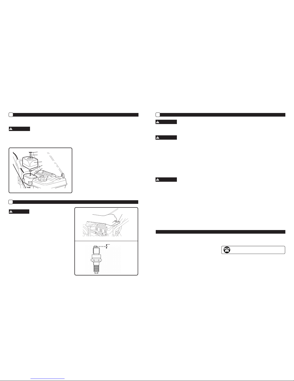
How to Check the Spark Plug
G
Spark Plug Model: Torch F7RTC
Only use the recommended spark plug or a spark plug with
the same temperature range. Using an improper spark
plug, an incorrect spark plug gap, or a dirty/fouled spark
plug can reduce engine performance and cause damage.
1. Stop engine and allow it to cool.
2. Remove spark plug wire from spark plug.
3.
Use the spark plug wrench and rod (included with edger)
to remove the spark plug. (See Figure 15)
4. Visually inspect the spark plug for cracks or damage. If
cracked, replace spark plug.
5. Clean carbon deposits. If excessive carbon build up,
replace spark plug.
6. Check that the gap of the spark plug is 0.028-0.031 in.
(0.7-0.8 mm). (See Figure 16)
7. Re-insert the spark plug and tighten using the spark
plug wrench and rod. (See Figure 15)
NOTE: Torque of spark plug is 18-22 foot-pounds (25-30 Nm)
8. Reattach spark plug wire to spark plug.
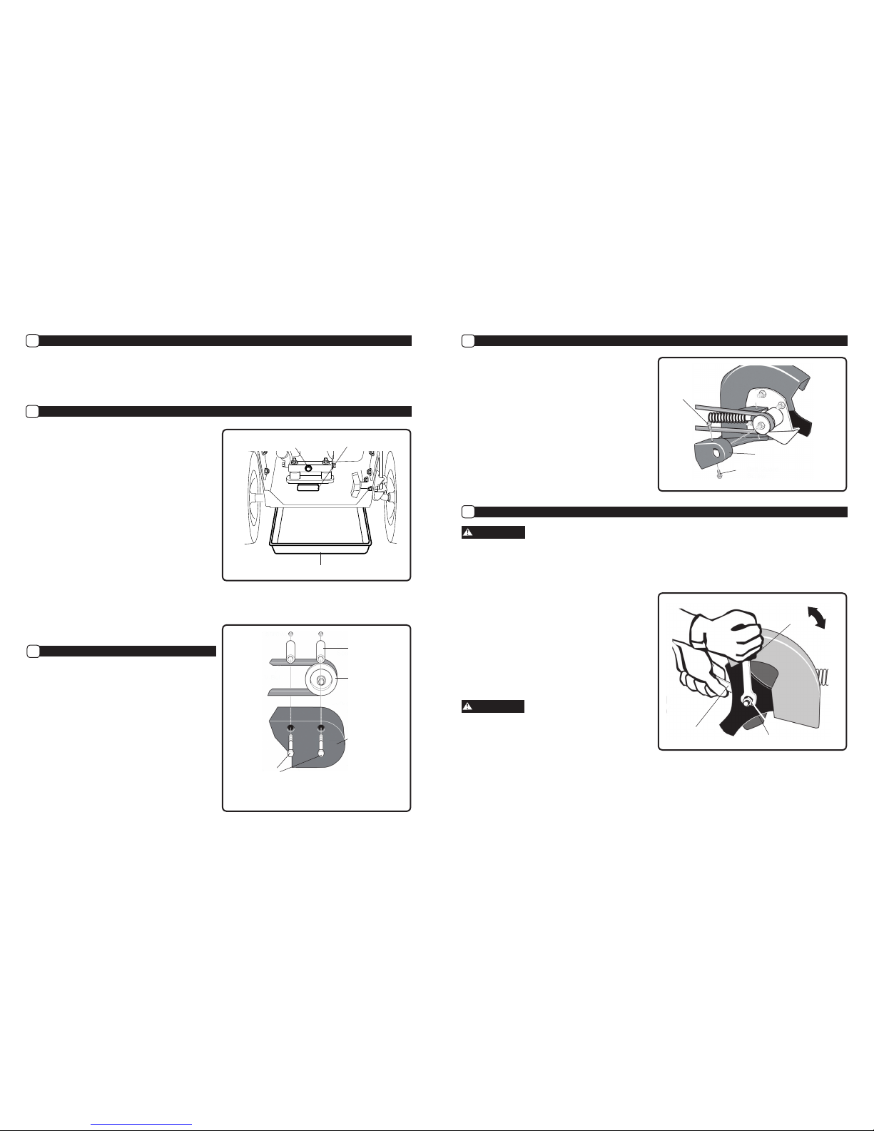
How to Clean the Air Filter
F
A dirty air filter will restrict air intake. Regular maintenance
of air cleaner will help improve engine performance and
reduce emissions.
Never clean air filter with gasoline or an easy ignited sol-
vent because it may cause explosion.
IMPORTANT: Only use replacement air filter from the manu-
facturer. To order spare parts call us at 1-800-737-2112
NOTE: Refer to Figure 14 when following steps below:
1. Remove the outer wing nut, washer, and air filter cover.
2. Remove the inner wing nut, and the air filter.
IMPORTANT: Use care when removing the air filter so dirt and
debris does not fall into the carburetor.
NOTE: Air filter is made up of an outer foam element and an
inner paper element.
3. Separate the outer foam element from the inner paper
element.
4.
Check the inside of the paper element for dirt or debris.
5. Check both elements for tears.
NOTE: If the inner paper element is dirty or if either element is
torn, replace with a new air filter from the manufacturer.
6. Clean the outer foam element by washing it thoroughly in
a solution of household detergent and water, or in a
nonflammable or high flash point solvent. Allow to
dry thoroughly. Then soak the foam element in clean
engine oil, and squeeze out all excess oil.
7. Clean the inner paper element by lightly tapping it
against a hard surface to remove excess dirt or by
blowing compressed air through the filter from the
inside out.
IMPORTANT: Do not attempt to brush dirt off the paper ele-
ment, as this will only embed dirt into the fibers.
8. Reinstall the cleaned out foam element onto the inner
paper element.
9. Reinstall the clean air filter and cover onto the unit by
reversing steps 1 and 2 above.
WARNING
Spark Plug
Wrench
and Rod
How to Prepare for Storage
H
Never store the edger indoors with fuel in the fuel tank. Never store in an enclosed, poorly ventilated area where fumes
could reach an open ame, a spark or a pilot light as on a furnace, water heater or clothes dryer. Allow engine to cool
before storing unit.
Do not remove gasoline while inside a building, near a re, or while you smoke. Gasoline fumes can cause an explosion
or a re.
NOTE: A yearly checkup or tune-up at an authorized service center will make sure that the edger will provide maximum
performance for the next season.
When the edger is put in storage for thirty days or more, the following steps should be followed to make sure the edger is in good
condition the next season.
1. Let the engine run until it is out of gasoline.
2. Change the oil by following instructions under “How to Change the Oil.”
3. Remove the spark plug from the cylinder. Pour one ounce of oil into the cylinder. Slowly pull the recoil-start grip so
that the oil will protect the cylinder. Install a new spark plug in the cylinder. Pull starter handle slowly a few times to
distribute oil. Pull recoil slowly until resistance is felt. This will close the cylinder valves.
DO NOT attach spark plug wire to spark plug when storing unit.
4. Clean edger. Remove all dirt, leaves, debris, grease, etc. from the edger - including cylinder cooling fans, recoil starter
cover holes, under fuel tank, and under mufer.
5. Check the edger for worn or damaged parts. Have damaged parts replaced if necessary.
6. Tighten any loose hardware.
7. Apply lubrication as directed in Maintenance section.
8. Put the unit in a building that has good ventilation.
9. Cover the edger with a breathing material.
Maintenance (Continued)
• Save all instructions
You may have further questions about assembling, operating, or maintaining this EDGER. If so, you can contact our
Technical Service Department at 1-800-737-2112 (English only).
You may also write to:
METL Corporate Office - CORRESPONDENCE ONLY
ATTN: Technical Service – METL
625 Barclay Blvd.
Lincolnshire, IL 60069
Technical Service
When contacting the Technical Service Department, have ready:
• Your Name
• Your Address
• Your Phone Number
• Model Number of Product
• Date of Purchase (include copy of receipt for written requests)
If you need assistance or have any questions, CALL
TOLL FREE: 1-800-737-2112.
1615
CAUTION
WARNING
WARNING
WARNING
Outer Wingnut
Washer
Air Filter Cover
Air Filter Element
Inner Wingnut
Figure 14
Figure 15
0.028 - 0.031 in
0.7 - 0.8 mm
Figure 16

Questions? Call Toll Free at 1-800-737-2112 Copyright © 2008 MAT Engine Technologies, LLC Questions? Call Toll Free at 1-800-737-2112 Copyright © 2008 MAT Engine Technologies, LLC
PROBLEM POSSIBLE CAUSE(S) SOLUTION(S)
Engine difficult to start 1. Out of fuel
2. Start lever is not compressed
3. Engine is not primed.
4. Spark plug wire disconnected
5. Fouled spark plug
6. Dirty Carburetor
7. Clogged air filter
8. Clogged fuel filter
9. Contaminated Fuel
1. Add fresh fuel
2. Pull start lever against handle
3. Push primer bulb 3 times - waiting 2
seconds between each push.
4. Attach spark plug wire to spark plug
5. Remove spark plug. Inspect. Replace if
necessary
6. Take unit to an authorized service center
for Carburetor cleaning
7. Remove and clean air filter
8. Remove fuel filter. Inspect. Replace if
necessary
9. Drain fuel tank. Clean fuel tank. Fill with
fresh fuel
Engine Problems
Engine smokes excessively
Engine runs very “rough”
Engine runs erratically
Engine cannot maintain full speed
1. No Engine Oil
2. Engine oil not at proper level
3. Fouled spark plug
4. Clogged air filter
5. Clogged fuel filter
6. Contaminated Fuel
7. Carburetor out of adjustment
1. Add engine oil
2. Check engine oil. Add or drain engine oil if
necessary
3. Remove spark plug. Inspect. Replace if
necessary
4. Remove and clean air filter
5. Remove fuel filter. Inspect. Replace if
necessary
6. Drain fuel tank. Clean fuel tank. Fill with
fresh fuel
7. Take unit to an authorized service center
for Carburetor adjustment
Excessive vibration / noise 1. Loose parts
2. Engine problems (above)
1. Tighten all fasteners
2. Refer to engine solutions (above)
Blade will not rotate 1. Debris interfering with blade
2. Blade loose
3. Belt Loose
1. Remove debris from around blade
2. Tighten blade nuts
3. Replace Belt
Engine will not stop Flameout wire terminals
disconnected
Connect handle and engine flameout wire
terminals
Blade will not cut properly Damaged or worn blade Replace blade
Frequent engine stalling 1. Excessive edging speed / depth
2. Engine problems (above)
1. Edge at a moderate pace. Make multiple
passes.
2. Refer to engine solutions (above)
Warranty
• Save all instructions
Always specify model number when contacting the factory.
We reserve the right to amend these specifications at any time without notice. The only warranty applicable is our standard written
warranty. We make no other warranty, expressed or implied. MAT Engine Technologies, LLC warrants this Lawn Edger and any parts
thereof, to be free from defects in material and workmanship for two years (90 days for commercial use or for reconditioned unit)
from the date of first purchase from an authorized dealer, provided that the product has been properly maintained and operated in
accordance with all applicable instructions. This warranty is extended only to the original retail purchaser. The bill of sales or proof of
purchase must be presented at the time a claim is made under this warranty. This warranty does not cover commercial, industrial, or
rental usage, nor does it apply to parts that are not in original condition because of normal wear and tear, or parts that fail or become
damaged as a result of misuse, accident, lack of proper maintenance, tampering, or alteration. Travel, handling, transportation, and in-
cidental costs associated with warranty repairs are not reimbursable under this warranty and are the responsibility of the owner. To the
full extent allowed by the law of the jurisdiction that governs the sale of the product, this express warranty excludes any and all other
expressed warranties and limits the duration of any and all implied warranties, including warranties of merchantability and fitness for
a particular purpose to two years from the date of first purchase, and MAT Engine Technologies, LLC’s liability is hereby limited to the
purchase price of the product and MAT Engine Technologies, LLC shall not be liable for any other damages whatsoever including indi-
rect, incidental, or consequential damages. Some states do not allow limitation of how long an implied warranty lasts or an exclusion or
limitation of incidental or consequential damages, so the above limitation of damages may not apply to you. This warranty provides the
original purchaser with specific rights.
For information regarding those rights, please consult the applicable state laws.
METL Corporate Office - CORRESPONDENCE ONLY
ATTN: Technical Service – METL
625 Barclay Blvd.
Lincolnshire, IL 60069
Southland™ LAWN EDGER Limited Warranty
A
1817
Maintenance (Continued)
• Save all instructions

Questions? Call Toll Free at 1-800-737-2112 Copyright © 2008 MAT Engine Technologies, LLC Questions? Call Toll Free at 1-800-737-2112 Copyright © 2008 MAT Engine Technologies, LLC
Warranty (Continued)
• Save all instructions
METL warrants that the product engine is free from defects in materials and workmanship which cause such engine to fail to conform
with the U.S. EPA or State of California emissions standards for small spark-ignited nonroad (off-road) engines – as applicable to your
METL product. Small spark-ignited off-road engines manufactured after January 1, 1995 and sold in the State of California and U.S. EPA-
certified small spark-ignited nonroad engines manufactured in model year 1997 or later and sold in all of the United States are covered
by this Emission Control System Warranty for a period of two years from the date of delivery to the original purchaser. This Emission
Control System Warranty is transferable to each subsequent purchaser for the duration of the warranty period. Emission Control System
Warranty repairs or replacements will be made without charge for diagnosis, parts or labor. A list of warranted parts is provided below.
Normal maintenance items, such as spark plugs, air filters and fuel filters that are included on the list of warranted parts are warranted
only up to the first scheduled required replacement interval for such item, as set forth in the Operator’s Manual. If any emission control
system part is repaired or replaced under the Emission Control System Warranty, it shall be warranted for the remainder of the applicable
warranty period. METL will also repair or replace other engine components damaged by a failure of any part covered by the Emission Con-
trol System Warranty during the Emission Control System Warranty Period. Only parts authorized and approved by METL may be used
in the performance of any Emission Control System Warranty repairs or replacements and will be provided without charge to the owner.
Unapproved, add-on, modified, counterfeit and/or “gray market” parts may not be used to modify or repair the METL engine. If such a part
has been used in the repair or maintenance of your engine, and an METL Authorized Service Center determines it is defective or causes a
failure of a part covered under the Emission Control System Warranty, your claim for repair of your engine or product may be disallowed.
METL shall not be held liable hereunder for failures of any warranted parts caused by the use of such an unapproved, add-on, modified,
counterfeit and/or “gray market” part.
You must take your power equipment engine or the product on which it is installed, along with evidence of the date of the sale to the
original purchaser, at your expense, to any METL Authorized Service Center during its normal business hours. To locate your nearest METL
Authorized Service Center, call (800) 737-2112. The product owner shall be responsible for any expenses or charges incurred for service
calls or transportation of the product or equipment engine to and from the METL Authorized Service Center, including any and all damages
or losses incurred during such transportation or shipment.
Failures other than those resulting from defects in material or workmanship are not covered by this Emission Control System Warranty.
This Emission Control System Warranty does not extend to emission control systems or parts which are affected or damaged by owner
abuse, neglect, improper maintenance, misuse, mis-fueling, improper storage, accident and/or collision, the incorporation of, or any use
of, any unapproved, add-on, modified, “graymarket” or counterfeit parts, unsuitable attachments, or the unauthorized alteration of any
part. This Emission Control System Warranty does not cover the regular replacement of normal maintenance items made in connection
with required maintenance services after the item’s first scheduled replacement, as set forth in the Operator’s Manual (e.g. spark plugs,
air filters, fuel filters, etc...).
METL disclaims any responsibility for loss of time or use of the engine, or the equipment in which the engine is installed, transportation,
commercial loss, or any other incidental or consequential damage. Any implied warranties are limited to the duration of this written limited
warranty. Some states do not allow limitations on how long an implied warranty lasts and/or do not allow the exclusion or limitation of
incidental or consequential damages, so the above exclusions and limitations may not apply to you.
This warranty gives you specific legal rights, and you may also have other rights which vary from state to state.
Warranty (Continued)
• Save all instructions
This MAT Engine Technologies, LLC (METL) outdoor power equipment engine complies with the emissions regulations of:
To the extent there is any conflict between this Emissions Control System Warranty and the equipment manufacturer’s warranty, this
Emissions Control System Warranty shall apply except where the equipment manufacturer’s warranty may provide a longer warranty
period. Please read your warranty rights and obligations carefully. Some sections of the warranty may not apply to the specific equipment
model you purchased. Unless specifically noted otherwise, the terms of the Emission Control System Warranty shall apply to all product
engines covered within this manual.
The California Air Resources Board, U.S. EPA and MAT Engine Technologies, LLC (METL) are pleased to explain the Emission Control Sys-
tem Warranty on your new outdoor power equipment engine.
California (applies only to Model No. S-WLE-1639)
In California, new spark-ignited small off-road equipment engines must be designed, built and equipped to meet the State’s stringent
anti-smog standards.
Other States, U.S. Territories
In other areas of the United States, your engine must be designed, built and equipped to meet the U.S. EPA emission standards for spark-
ignited engines at or below 19 kilowatts.
All of the United States
MAT Engine Technologies, LLC (METL) must warrant the emissions control system on your power equipment engine for the periods of time
listed below provided there has been no abuse, neglect or improper maintenance of your power equipment engine. Where a warrantable
condition exists, METL will repair your power equipment engine at no cost to you including diagnosis, parts and labor.
The emissions control system is warranted for two years. If any emissions-related part on your engine is defective, the part will be repaired
or replaced by METL.
Owner’s Warranty Responsibility
As the power equipment engine owner, you are responsible for the performance of the required maintenance listed in your owner’s
manual. METL recommends that you retain all receipts covering maintenance on your power equipment engine, but METL can not deny
warranty solely for the lack of receipts or for your failure to ensure the performance of all scheduled maintenance.
As the power equipment engine owner, you should however be aware that METL may deny your warranty coverage if your power equip-
ment engine or a part has failed due to abuse, neglect, improper maintenance or unapproved modifications.
You are responsible for presenting your power equipment engine to a distribution center or service center authorized by METL as soon as
the problem exists. The warranty repairs should be completed in a reasonable amount of time, not to exceed 30 days.
If you have any questions regarding your warranty rights and responsibilities, you should contact
MAT Engine Technologies, Inc.
625 Barclay Boulevard
Lincolnshire, IL 60069
Tel: 1-800-737-2112
Your Warranty Rightes and Obligations:
How to Obtain Warranty Service:
Exclusions:
Limitations of Liability:
Emisson Control System Warranty
B
Southland Model No. Regulatory Agency
S-WLE-1639-[E] United States Environmental Protection Agency (“U.S. EPA”)
S-WLE-1639 United States Environmental Protection Agency (“U.S. EPA”) and State of California
Manufacturer’s Warranty Coverage:
Warranty Coverage:
19 20

Questions? Call Toll Free at 1-800-737-2112 Copyright © 2008 MAT Engine Technologies, LLC Llame sin costo al: 1-800-737-2112 Copyright © 2008 MAT Engine Technologies, LLC
Adentro encontrará:
Página
Instrucciones de seguridad 23
Instrucciones de seguridad importantes 24-26
Especificaciones del producto 27
Piezas y características 27
Montaje 28
Preparación del motor 29-30
Uso 30-33
Mantenimiento 34-38
Servicio Técnico 38
Diagnóstico y resolución de problemas 39
Garantía 40-43
Manual del usuario
Edger King
163 cc, 4 Ciclos
IMPORTANTE:
Le agracedemos haber comprado la recortadora Southland™ Bordeadora.
Este manual le ofrece las instrucciones completas para operar y mantener seguramente la bordeadora. Lea y conserve
estas instrucciones. Refiérase a este manual cada vez, antes de utilizar la bordeadora.
Anote lo siguiente como referencia:
Código de fecha de fabricación: _________
Fecha de compra: adjunte una copia de su recibo de compra.
Número gratuito de asistencia al consumidor: 1-800-737-2112
CONSERVE ESTE MANUAL COMO REFERENCIA
Núm. de modelos. S-WLE-1639 [E]
S-WLE-1639
Si tiene una duda o un problema...
LLAME SIN COSTO AL: 1-800-737-2112
Este producto contiene productos químicos reconocidos por el Estado de California como causantes de cáncer, defectos
de nacimiento u otros daños de reproducción.
ADVERTENCIA
SYSTEMS COVERED BY THIS WARRANTY: PARTS DESCRIPTION:
Fuel Metering System
Carburetor assembly (if so equipped) and its internal compo-
nents; fuel filter (if so equipped), carburetor gaskets, fuel pump (if
so equipped)
Air Induction System Intake pipe/ manifold, air cleaner
Ignition System Spark plug1, ignition module / coil
Exhaust System Catalytic muffler assembly (if so equipped), muffler gasket, ex-
haust manifold
Crankcase Breather Assembly Breather connection tube
Miscellaneous Parts Used in Above Systems Hoses, belts, connectors and assemblies
Evaporative Emissions Components² Fuel line, fuel line fittings, clamps, fuel tank, carbon canister, can-
ister mounting brackets, carburetor purge port connector
1Covered up to the first required replacement only. See the Maintenance Schedule
² As applicable to your product engine emissions certifications
Warranty (Continued)
• Save all instructions
Limitation of Liability (cont.):
2221

Llame sin costo al: 1-800-737-2112 Copyright © 2008 MAT Engine Technologies, LLC Llame sin costo al: 1-800-737-2112 Copyright © 2008 MAT Engine Technologies, LLC
Ubicación para llenado de aceite.
No sobrellenar
Ubicación para llenado de
gasolina.
Palanca de control de la profundidad
Mover la palanca hacia adelante para
aumentar la profundidad de corte
Posición de arranque
Barra de control de arranque/paro
Soltar la barra para parar el motor.
Enganchar la barra de control de
arranque/paro para arrancar el motor y
mantenerlo en marcha.
Siempre verificar que los conductores
a tierra estén conectados antes de
poner la unidad en marcha
Oprimir el bulbo del cebador 3 veces
antes de arrancar un motor frío.
Importante: no cebar para arrancar
un motor caliente.
Indica ADVERTENCIA, PELIGRO o CUIDADO.
Usar protección ocular que cumpla con la
norma ANSI Z87.1 y protección auditiva.
Leer el Manual del usuario antes de utilizar
esta máquina. El no acatar las directrices
podría conducir a lesiones graves.
Desconectar el cable de la bujía al no estar
en uso o antes de reparar, limpiar o dar
mantenimiento a la unidad.
Objetos lanzados. Retirar toda roca, piedra y
objeto extraño que pudiera ser lanzado por la
máquina.
Los gases del escape del motor contienen
monóxido de carbono, un gas inodoro y letal.
JAMÁS hacer funcionar la unidad en espacios
interiores o en un área con ventilación
deficiente.
Mantener a los circunstantes a una distancia
segura. JAMÁS usar la máquina ante la
presencia de niños.
NO tocar el silenciador caliente ni el cilindro.
Estas piezas están extremadamente cali-
entes durante el funcionamiento y podrían
permanecer calientes durante un período de
tiempo corto después del funcionamiento.
La cuchilla rotativa puede causar lesiones
graves. Mantener las manos y los pies
alejados de la cuchilla.
Para reducir el riesgo de incendio, limpiar el
combustible y aceite derramados y mantener
la unidad libre de residuos. La gasolina es
extremadamente inflamable. Dejar que la
máquina enfríe antes de reabastecerla de
combustible.
Definiciones de seguridad
• Guardar estas instrucciones
Símbolos de advertencia para seguridad
Símbolos de control y funcionamiento
Indica una situación de riesgo inminente que, al no protegerse, provocará lesiones graves o la
muerte.
Indica una situación potencialmente peligrosa que, al no protegerse, podría provocar lesiones
graves o la muerte.
Indica una situación potencialmente peligrosa que, al no protegerse, podría causar lesiones
leves o daños materiales.
ADVERTENCIA
Los símbolos siguientes se utilizan en el producto y en este manual para alertar al usuario sobre riesgos potenciales de
seguridad. Leerlos detenidamente y entender su significado.
Símbolos de alerta para sequradad
Los símbolos siguientes se pueden encontrar en la bordeadora. Leerlos detenidamente y entender su significado.
PUSH TO PRIME
INCREASE
CUTTING
DEPTH
STA R T
ENGINE
STOP
START /
RUN
Instrucciones de seguridad importantes
WIRES MUST BE
CONNECTED
DANGER
Instrucciones de seguridad importantes
• Conserve todas las instrucciones
Instrucciones de seguridad importantes
RESPONSABILIDAD DEL USUARIO
1. Leer detenidamente y seguir estas instrucciones de seguridad. Hacer caso omiso de éstas puede conducir a lesiones
graves.
2. Conózcase el producto. Leer y entender este manual antes de utilizar la unidad. Comparar las ilustraciones con la
unidad. Aprenderse la ubicación y la función de todos los controles. Un entendimiento exhaustivo de la unidad antes
de utilizarla redundará en rendimiento y seguridad óptimos.
3. Seguir todas las instrucciones al montar la unidad. Si se compró la unidad ya montada, el usuario ha de revisar la
unidad cuidadosamente para asegurarse de que se montó de conformidad con las instrucciones en el manual
antes de utilizarla.
4. Inspeccionar la bordeadora periódicamente. Vericar que no haya piezas dobladas, dañadas o ojas.
5. Utilizar este equipo únicamente para su uso previsto.
6. Utilizar la unidad solo con protectores, pantallas y otros elementos de seguridad instalados y en buenas condiciones.
7. Dar mantenimiento a la unidad solo con piezas de repuesto autorizadas o aprobadas.
8. Completar la totalidad del mantenimiento de la unidad.
ADVERTENCIA
La presencia de este símbolo señala precauciones de seguridad importantes. Signica: “¡Atención! ¡Ponte alerta! Tu
seguridad está de por medio.”
ADVERTENCIA
El gas de escape del motor, algunos de sus constituyentes y ciertos componentes de vehículos contienen o emiten
substancias químicas que, consta al Estado de California, producen cáncer y malformaciones congénitas u otros daños
reproductivos.
ADVERTENCIA
Para evitar el arranque accidental al montar, transportar, ajustar o efectuar reparaciones, siempre desconectar el cable
de la bujía y colocarlo donde no pueda entrar en contacto con ésta.
SEGURIDAD DURANTE LA PREPARACIÓN
ADVERTENCIA
•Leer, entender y acatar todas las instrucciones en la máquina y en los manuales. Familiarizarse completamente con
los controles y el uso apropiado de la bordeadora antes del arranque. Sépase cómo parar el motor rápidamente.
•Familiarizarse con todos los marbetes de seguridad y funcionamiento de este equipo.
ADVERTENCIA
•Inspeccionar completamente el área en que se va a utilizar la bordeadora y retirar todo objeto extraño. Esta bordeadora
puede lanzar objetos pequeños a gran velocidad y causar lesiones personales o daños a la propiedad. Mantenerse
alejado de objetos frágiles, tales como ventanas de viviendas, parabrisas de automóviles, invernaderos, etc.
• Vericar que todas las tuercas y pernos estén apretados y que el equipo esté en buenas condiciones.
ADVERTENCIA
•Siempre verificar que el cable de extinción esté conectado antes de arrancar el motor.
SEGURIDAD DURANTE EL USO
•Jamás permitir que niños o adolescentes jóvenes utilicen la bordeadora.
ADVERTENCIA
•Mantener el área de trabajo libre de circunstantes, particularmente niños pequeños y mascotas.
•Permitir solo a individuos responsables, familiarizados con las instrucciones, utilizar la bordeadora.
ADVERTENCIA
• No utilizar la bordeadora bajo la inuencia de alcohol, fármacos u otro medicamento que pudiera causar somnolencia
o afectar la capacidad de utilizar la máquina de manera segura.
2423
PELIGRO
CUIDADO

Llame sin costo al: 1-800-737-2112 Copyright © 2008 MAT Engine Technologies, LLC Llame sin costo al: 1-800-737-2112 Copyright © 2008 MAT Engine Technologies, LLC
Instrucciones de seguridad importantes (la siguiente)
• Conserve todas las instrucciones
SEGURIDAD DURANTE EL USO (la siguiente)
Instrucciones de seguridad importantes
Instrucciones de seguridad importantes (la siguiente)
• Conserve todas las instrucciones
•No utilizar esta máquina si se es mental o físicamente incapaz de utilizarla de manera segura.
•Always wear ANSI compliant safety goggles or safety glasses with side shields when operating edger to protect your
eyes from foreign objects, which can be thrown from the unit.
•Al utilizar la bordeadora, siempre usar gafas de seguridad con pantallas laterales, homologadas por ANSI, para prote
gerse los ojos contra objetos extraños que pudieran ser lanzados por la unidad.
•Vestir indumentaria apropiada tal como una casquillo o chaqueta de manga larga. También, vestir pantalones largos.
NO vestir pantalones cortos. NO vestir indumentaria holgada que pudiera atorarse en este equipo.
•Siempre vestir guantes de trabajo y calzado robusto tal como zapatos de cuero para trabajo o botas cortas. Éstos
protegen los tobillos y la tibia contra palos pequeños, astillas y otros despojos lanzados. Asimismo, éstos mejoran la
tracción.
•Es aconsejable vestir indumentaria para proteger la cabeza contra golpes de partículas pequeñas lanzadas, o contra
golpes de ramas bajas, ramitas u otros objetos que pudieran pasar desapercibidos por el usuario.
ADVERTENCIA
•No colocar ni las manos ni los pies cerca de piezas rotativas o debajo de las mismas.
•Tener sumo cuidado al utilizar la bordeadora sobre o al cruzar accesos, andenes o caminos con grava. Mantenerse
alerta por peligros ocultos o tránsito.
ADVERTENCIA
• Tener cuidado para no deslizarse o caerse. Siempre asegurar el apoyo de los pies; mantener una sujeción rme del
asidero y caminar; jamás correr.
•Mirar hacia atrás y tener cuidado al retroceder.
•Jamás utilizar la bordeadora sin buena visibilidad o luz.
PELIGRO
•No poner en marcha el motor en espacios interiores o dentro de un área cerrada. Los gases del escape son peligrosos,
contienen MONÓXIDO DE CARBONO, un GAS INODORO Y LETAL.
•Jamás dejar la bordeadora desatendida mientras el motor está en marcha. Parar el motor y asegurarse que todas las
piezas móviles hayan parado. Desconectar el cable de la bujía.
•No sobrecargar la capacidad de la bordeadora al intentar un corte demasiado profundo a demasiada velocidad.
•Si la bordeadora comenzara a vibrar anormalmente, parar el motor, desconectar el cable de la bujía y evitar que éste
haga contacto con la bujía. Tratar de identicar la causa inmediatamente. Generalmente, la vibración indica problemas.
• Tener cuidado con agujeros, zurcos, abultamientos u otro terreno escabroso. El pasto alto puede ocultar obstáculos.
SEGURIDAD DEL COMBUSTIBLE
ADVERTENCIA
• La gasolina es estremadamente inamable. Los vapores de gasolina pueden explotar si se los enciende. Manipularla
con cuidado.
•Utilizar un contenedor aprobado.
•Revisar el suministro de combustible antes de cada uso, dejar espacio para expansión puesto que el calor del motor
y/o el sol puede(n) causar la expansión del combustible.
•Llenar el tanque de combustible al aire libre, con sumo cuidado. Jamás llenar el tanque de combustible en espacios
interiores.
•Jamás retirar la tapa del combustible ni abastecer combustible con el motor en marcha. Dejar que el motor enfríe
antes de reabastecerlo de combustible.
ADVERTENCIA
•No fumar mientras se reabastece combustible.
•Después del reabastecimiento de combustible, colocar nuevamente la tapa del tanque de combustible de manera
segura y enjugar el combustible derramado.
• Jamás almacenar combustible o la bordeadora con combustible en el tanque dentro de un edicio donde los vapores
podrían llegar a una llama abierta.
SEGURIDAD DE ALMACENAMIENTO
•
Siempre consultar las instrucciones del Manual del usuario para obtener información importante pormenorizada si se va
a guardar la bordeadora durante un período de tiempo prolongado.
• Jamás almacenar la bordeadora con combustible en el tanque dentro de un edicio donde haya fuentes de
ignición tales como calentadores de agua, calentadores unitarios, secadoras de ropa, etc.
•Para reducir el riesgo de incendio, mantener la bordeadora libre de césped, hojas y acumulación de otros residuos.
•Dejar que el motor se enfríe antes de almacenarlo en cualquier recinto.
REPARACIÓN, MANTENIMIENTO Y SEGURIDAD DE AJUSTE
•Después de golpear un objeto extraño, parar el motor. Desconectar el cable de la bujía y mantenerlo alejado de ésta
para evitar un arranque accidental. Inspeccionar exhaustivamente la bordeadora para determinar si ha sufrido
daños. Si está dañada, efectuar las gestiones para que un técnico capacitado la repare antes de arrancarla y utilizarla
nuevamente.
ADVERTENCIA
• Parar el motor antes de limpiar, reparar o inspeccionar la unidad. Vericar que todas las piezas móviles hayan parado.
Dejar que el motor se enfríe. Desconectar el cable de la bujía y alejarlo de ésta.
• Jamás intentar ajuste alguno mientras el motor esté en marcha, excepto cuando así lo recomiende el fabricante
especícamente.
•Mantener la bordeadora en condiciones de funcionamiento seguro. Revisar todos los sujetadores a intervalos
frecuentes para una sujeción apropiada.
•Al dar mantenimiento a la bordeadora o repararla, no inclinar la máquina lateral o longitudinalmente a menos que así lo
instruya este Manual especícamente. Los procedimientos de mantenimiento y reparación se pueden efectuar con la
bordeadora en la posición vertical. Algunos procedimientos serán más fáciles si se coloca la máquina sobre una
plataforma o supercie de trabajo elevada.
•Utilizar solo equipo original o piezas de repuesto autorizadas.
ADVERTENCIA
• Jamás manipular imprudentemente los dispositivos de seguridad. Vericar el funcionamiento apropiado de los mismos
periódicamente.
• No cambiar la conguración del regulador del motor ni sobreacelerar el motor.
•Limpiar y reemplazar los marbetes de seguridad e instrucciones según sea necesario.
• Para prevenir el sobrecalentamiento del motor, siempre tener el ltro de impurezas limpio e instalado en el motor
instalado.
SEGURIDAD DE NIÑOS
ADVERTENCIA
•Accidentes trágicos pueden ocurrir si el usuario no está alerta a la presencia de niños. A menudo, los niños se ven
atraídos por la bordeadora y el bordeado mismo.
•Mantener a los niños fuera del área de bordeado y bajo la supervisión de un adulto responsable.
•Jamás suponer que los niños permanecerán donde se los vio la última vez.
•Estar alerta y apagar la bordeadora si algún niño entra en el área.
•Antes de retroceder y mientras se retrocede, ver hacia atrás y hacia abajo para asegurarse que no haya niños.
•Jamás permitir que niños utilicen la bordeadora.
•Tener sumo cuidado al utilizar la bordeadora cerca de esquinas sin visibilidad clara, arbustos, árboles u otros objetos
que pudieran obstruir la visión.
25 26

Llame sin costo al: 1-800-737-2112 Copyright © 2008 MAT Engine Technologies, LLC Llame sin costo al: 1-800-737-2112 Copyright © 2008 MAT Engine Technologies, LLC
ESPECIFICACIONES DE LA BORDEADORA
• Conserve todas las instrucciones
Piezas y características
1. Barra de control de arranque/paro Barra en el asidero que
permite que la marcha del motor. Al soltársela, el motor
parará.
2. Bulbo de cebado Inyecta mezcla de combustible al car-
burador para arrancar el motor en frío.
3. Silenciador Ubicación del escape del motor.
4. Rueda trasera ajustable
La rueda trasera derecha es ajust-
able para nivelar la bordeadora al efectuar cortes a lo largo
de un cordón de acera (franqueo de cordón de acera).
5. Rueda frontal ajustable Las ruedas frontales son ajust-
ables de lado a lado para equilibrar la unidad. Asimismo,
se pueden ajustar las ruedas frontales hacia abajo para
franquear cordones de aceras.
6. Empuñadura de arrancador de retroceso El motor está pro-
visto de un arrancador de retroceso de tiro cómodo.
7. Palanca índice Permite ajustar el ángulo de corte a 15
grados, 0 grados (vertical),o -15 grados. Para cambiar el
ángulo, tirar de la palanca índice y rotar el conjunto del
manguito (eje hueco) al ángulo deseado.
8. Cuchilla Elemento cortante rotativo.
9. Protector de la cuchilla Evita el lanzamiento de piedras y
despojos al operador.
10. Bujía / Cable de la bujía
Brinda la chispa para encender la
mezcla de aire / combustible. Al dar mantenimiento a la unidad,
es preciso desconectar y retirar el cable de la bujía.
11. Filtro de aire Retira despojos y contaminantes del aire
de admisión, para un funcionamiento uniforme del motor
con un nivel de emisiones bajo.
12. Placa selectora de profundidad, 13. Palanca de
control de la profundidad, 14. Varilla de control Se la utiliza
para controlar la profundidad de corte de la
bordeadora
15. Terminales del cable de extinción Es preciso que estén
conectados para el funcionamiento correcto de la barra de
control de arranque/paro.
Peso de la unidad ........................... 32 kg
Profundidades de corte .......... 0-76 mm (0-3.0 pulg.)
Blade Diameter................ 9 in. (228 mm), 3 point
Tipo de gasolina.... Regular Unleaded / 88 Octane (min.)
Capacidad de gasolina.................. 3.3 L (3.5 qt.)
Tipo de aceite (API SG-SL) .........................
Se recomienda 10W-30 para toda temperatura en servicio.
Véase la página 29 para mayor información.
Capacidad de aceite................... 562 ml (19 oz)
Modelo de bujía ....................... Torch F7RTC
Salto de chispa de la bujía... 0.028-0.031 in. (0.7-0.8 mm)
Tipo de motor ...... 4 tiempos, solo cilindro, válvula en la
culata
Cilindrada .................................. 163cc
RPM .................................. 3000 RPM
Par de torsión nominal .. Par de torsión bruto de 8.47 N·m
(6.25 ft·lbf) según SAE J1940
Diámetro interior x carrera .......68X48 mm (2.7X1.8 in.)
Huelgo de la válvula de admisión . . . . 0.08-0.12 mm
Huelgo de la válvula de escape . . . . . . 0.15-0.20 mm
Ángulo de ignición ...................... 25 Degrees
Instrucciones de seguridad importantes
Leer y seguir las instrucciones de montaje. No descartar ninguna pieza ni materiales antes de concluirse el montaje de
la unidad. Las referencias al lado derecho o izquierdo de la bordeadora toman como base el punto de vista del usuario
ubicado detrás de la unidad.
No utilizar la bordeadora si ésta está averiada o no está armada completa y correctamente.
Antes de efectuar algún montaje o mantenimiento de la unidad, retirar el cable de la bujía.
Al montar la bordeadora, siempre usar gafas de seguridad con pantallas laterales, homologadas por ANSI.
Montaje
• Conserve todas las instrucciones
NOTA: Consultar la figura 2 al seguir los pasos enumerados a
continuación:
1. Montar el asidero superior sobre el asidero inferior con
los dos (2) pernos para tubo y las dos (2) tuercas
plásticas de orejetas (Véase la figura 2).
Apretar firmemente a mano las tuercas de orejetas.
2. Deslizar un extremo de la varilla de control en el agujero
de la palanca de control de la profundidad. Asegurarla
con una chaveta de dos patas.
3. Deslizar el otro extremo de la varilla de control a través
del agujero del brazo del manguito. Asegurarla con la
segunda chaveta de dos patas.
4. Instalar la empuñadura del arrancador de retroceso a
través de la guía de la cuerda, y encajarla en posición
por torsión.
5. Retirar el inserto temporal del terminal del cable de
extinción del motor.
6. Conectar los cables de extinción del motor y el asidero.
Utilizar la atadura de alambre para asegurar el cable
suelto al asidero.
En la caja se encontrarán los componentes siguientes.
Las cantidades se muestran entre paréntesis.
1. (1) Bordeadora
2. (1) Manual del usuario de la bordeadora
3. (1) Asidero superior
4. (1) Varilla de control
5. (1) Envase de aceite automotriz SAE 30
6. (1) Bolsa de piezas con el contenido siguiente:
(2) Chaveta de dos patas
(2) Tuercas plásticas de orejetas (M8)
(2) Pernos para tubo M8 x 35 mm
(1) Atadura de alambre
(1) Llave con varilla para bujía
1. Sacar todas las piezas y componentes de embalaje
2. Utilizar una cuchilla multiuso para cortar las cuatro
esquinas verticales y colocar los costados de la caja
sobre el piso, alrededor de la bordeadora.
3. Sacar el resto del embalaje
4. Rodar la unidad para sacarla de la caja y colocarla sobre
una superficie firme a nivel.
Cómo sacar la bordeadora de la caja
A
Cómo montar el asidero
B
ES NECESARIO conectar los cables de extinción para el
funcionamiento correcto del motor. El no conectarlos puede
conducir a lesiones graves.
2827
ADVERTENCIA
ADVERTENCIA
ADVERTENCIA
Figura 1
VISTA POSTERIOR
VISTA FRONTAL
Asidero
superior
Asidero
inferior
Chaveta de
dos patas
Varilla de contro
Brazo de
apoyo del
manguito
Chaveta de
dos patas
Perno
para tubo
Figura 2
Palanca de
control de la
profundidad
Empuñadura
de arrancador
de retroceso
Tuerca
plástica de
orejetas
Cable de
extinción del
asidero
Cable de
extinción del
motor
Terminal de
conexión
7
3
10
1
6
2
4
5
9
8
13
12
14
11
15
ADVERTENCIA

Llame sin costo al: 1-800-737-2112 Copyright © 2008 MAT Engine Technologies, LLC Llame sin costo al: 1-800-737-2112 Copyright © 2008 MAT Engine Technologies, LLC
Preparción del motor
• Conserve todas las instrucciones
Aceite de motor
A
El motor se envía sin aceite. El no agregar aceite causará
daños severos al motor.
Se incluye un envase de aceite automotriz SAE 30 con
la bordeadora. Consultar el diagrama a la derecha para
obtener información sobre tipos alternativos de aceite a
usarse a diferentes temperaturas. Siempre utilizar un aceite
detergente de alta calidad clasificado «Para servicio SG, SH,
SJ» o superior. No utilizar aditivos especiales.
Siempre usar el tipo de aceite recomendado. El uso de
aceite sucio o tipo de aceite incorrecto --tal como aceite para
motores de dos tiempos-- acortará la vida útil del motor.
NOTA: La capacidad de aceite del motor es 562 ml. Para el
primer llenado, sencillamente agregar al cárter del cigüeñal
todo el contenido del envase de aceite provisto.
Antes de revisar el aceite, verificar que el motor esté
apagado y que se haya desconectado de la bujía el cable
de la misma.
1. Colocar la bordeadora en una supercie a nivel y
asegurarse que las ruedas ajustables estén conguradas
de manera tal que el marco principal de la bordeadora
esté a nivel.
2. Retirar la tapa de llenado de aceite / varilla de aforar y
enjugarla con un paño. (Véase la Figura 3)
3. Colocar nuevamente la varilla de aforar en posición y NO
enroscarla. Retirarla y revisar el nivel de aceite.
4. Al tenerse un nivel lleno de aceite, el aceite alcanzará el
límite superior en la varilla aforadora. Si el nivel de
aceite está cerca del límite inferior o por debajo de éste,
se ha de agregar aceite. (Véase la figura 4)
5. Agregar aceite lentamente hasta que el nivel del aceite
alcance el límite superior de la varilla aforadora. Utilizar
un embudo o boquilla para reducir derrames.
Verificar el nivel de aceite frecuentemente durante el
llenado. NO SOBRELLENAR. NO SUBLLENAR. Hacer
marchar el motor con un nivel inadecuado de aceite causará
daños severos al motor.
6. Colocar la varilla aforadora en posición y apretarla.
7. Limpiar todo aceite derramado.
CÓMO REVISAR EL ACEITE Y LLENAR HASTA EL NIVEL APROPIADO
Preparción del motor (la siguiente)
• Conserve todas las instrucciones
Combustible
B
Uso
• Conserve todas las instrucciones
Antes de arrancar el motor
A
Antes de arrancar el motor, leer el Manual del usuario. Familiarizarse con la ubicación y función de todos los controles.
Sépase cómo parar el motor rápidamente.
Antes de arrancar el motor, verificar que se hayan conectado los terminales de los cables de extinción.
•La gasolina es extremadamente inflamable y los vapores pueden explotar si se inflaman. Manipularla con cuidado.
• Utilizar un contenedor aprobado.
•Mantener la gasolina en un área bien ventilada, alejada de chispas, llamas abiertas u otras fuentes de ignición.
•Mantener la gasolina fuera del alcance de niños.
Usar gasolina fresca, limpia, regular, sin plomo, de 88 octanos como mínimo.
NO usar gasolina con plomo, gasohol, metanol ni combustible diésel. No mezclar el aceite con gasolina. NO permitir que
la gasolina se contamine con polvo, agua o despojos.
El uso de un tipo incorrecto de combustible o de combustible contaminado causará daños severos al motor.
NOTA: La capacidad del tanque de combustible es aproximadamente 3.3 l (3.5 cuartos)
CÓMO LLENAR EL MOTOR CON COMBUSTIBLE
Antes de intentar arrancar el motor, revisar los pasos siguientes:
1. Se ha montado la unidad según todas las instrucciones de montaje.
2. Los terminales de los cables de extinción están conectados.
3. Se ha inspeccionado la unidad para determinar si hay piezas averiadas o faltantes.
4. No hay piezas restantes en la caja.
• Apagar el motor y dejarlo enfriar durante varios minutos antes de quitar la tapa de combustible o agregar combustible.
• Jamás llenar el tanque de combustible en espacios interiores.
• No fumar durante el abastecimiento de combustible.
1. Limpiar la superficie alrededor de la tapa de combustible para evitar contaminación. (Véase la Figura 3)
2. Aflojar la tapa del combustible lentamente. Después de retirar la tapa, colocarla sobre una superficie limpia.
3. Verter el combustible en el tanque. Tener cuidado para evitar derrames.
NO SOBRELLENAR con combustible. Dejar espacio para que el combustible se expanda debido al calor del motor y/o
del sol.
4. Antes de colocar nuevamente la tapa de combustible, inspeccionar y limpiar el sello de la tapa de combustible.
5. Colocar nuevamente la tapa de combustible y apretarla a mano de manera segura.
6. Limpiar todo combustible derramado.
29 30
CAUTION
CAUTION
SAE
TEMP 100° F
40° C
-20
-20-30 -10
0
0
20
2010
40 60 80
30
Ambient Service Temperature
SAE 10W-30
SAE 30
ADVERTENCIA
CUIDADO
CUIDADO
CUIDADO
ADVERTENCIA
ADVERTENCIA
ADVERTENCIA
ADVERTENCIA
CUIDADO
circundante servicio temperatura
Tapa de llenado
de aceite / Varilla
aforadora
Límite superior
Límite inferior
Figura 3
Figura 4
Tapa de llenado de
aceite / Varilla
aforadora
Tapa del tanque
de combustible
Ruedas ajustables
ADVERTENCIA

Llame sin costo al: 1-800-737-2112 Copyright © 2008 MAT Engine Technologies, LLC Llame sin costo al: 1-800-737-2112 Copyright © 2008 MAT Engine Technologies, LLC
Uso
• Conserve todas las instrucciones
Antes de arrancar el motor (la siguiente)
A
5. El aceite del motor está al nivel apropiado.
6. Se ha abastecido el tanque de combustible con gasolina
fresca, limpia, regular, sin plomo.
7. El cable de la bujía está conectado a la bujía.
8. Se ha movido la bordeadora a la ubicación deseada.
9. La bordeadora está en una superficie a nivel.
Durante el uso, mantener a todo circunstante, especialmente
NIÑOS, alejados
IMPORTANTE: El sistema de escape de esta unidad está
provisto de un silenciador con supresor de chispas. La
manipulación imprudente o el retiro del supresor de chispas
viola la sección 442 del California Public Resources Code
(Código de Recursos Públicos de California) así como
también otras leyes estatales y federales pertinentes.
Cómo arrancar el motor
B
Jamás hacer funcionar el motor en espacios interiores o en un área con ventilación deficiente. Los gases del escape del
motor contienen monóxido de carbono, un gas inodoro y letal.
Los despojos lanzados por la bordeadora pueden causar lesiones oculares graves. Siempre utilizar gafas protectoras
o pantallas oculares que cumplan las normas ANSI al utilizar la bordeadora. Si se usa anteojos, colocar una máscara
protectora de visión amplia, certificada por OSHA, sobre los anteojos.over your eyeglasses.
1. Revisar TODOS los pasos en la sección “ANTES DE
ARRANCAR EL MOTOR”. En particular, verificar que:
a. La unidad esté montada correctamente
b. Los terminales de los cables de extinción están
conectados.
c. El aceite del motor está al nivel apropiado.
d. Se haya abastecido gasolina fresca, sin plomo
e. El cable de la bujía esté conectado a la bujía
2. Mover la palanca de control de la profundidad a la
posición de arranque. (Véase la figura 6).
3. Oprimir el bulbo del cebador 3 veces; esperar 2
segundos entre cada opresión. (Véase la Figura 5)
NOTA: No es necesario al arrancarse nuevamente un motor
caliente.
4. Sujetar firmemente el asidero de la bordeadora
con la mano izquierda y tirar de la barra de control de
arranque/paro contra el asidero. (Véase la figura 6).
NOTA: El motor no arranca si la barra de control de arranque/
paro no está halada hacia atrás contra el asidero.
5. Asir firmemente la empuñadura del arrancador de r
etroceso con la mano derecha. (Véase la figura 6).
6. Tirar del arrancador de retroceso lentamente hasta
sentir tensión en la cuerda del arrancador. Luego,
tirar rápidamente de la empuñadura del arrancador
de retroceso para desarrollar completamente la cuerda
del arrancador. NO permitir que la cuerda del
arrancador retroceda violentamente. Dejar que la cuerda
del arrancador se reenrolle lentamente.
7. Si el motor no arranca después de 5 ó 6 intentos, ver
la instrucción en la “Tabla de diagnóstico y resolución de
problemas”.
Mantener las manos, los pies, el cabello, y la ropa holgada
alejados de toda pieza móvil. No tocar el silenciador y las
áreas circundantes: las temperaturas podrían ser superiores
a 65.6 °C (150 °F). Mantener todos los dispositivos y
pantallas de seguridad en posición.
PELIGRO
Uso (la siguiente)
• Conserve todas las instrucciones
Cómo parar la bordeadora
C
Soltar la barra de control de arranque/paro. Esto conectará a tierra el extinguidor y parará el motor.
Es preciso conectar los terminales de los cables de extinción de manera segura para que la barra de control de
arranque/paro funcione. Consultar la sección “Cómo montar el asidero”.
Cómo cambiar la profundidad de corte de la bordeadora
D
Mover la palanca de control de la profundidad hacia
adelante para aumentar la profundidad de corte. (Véase
la figura 7).
NOTA: Hay 6 selecciones de profundidad de corte, desde
aproximadamente el nivel del terreno hasta una profundidad
de 76 mm (3 pulgadas).
No sobrecargar la capacidad de la bordeadora al intentar
bordear a demasiada profundidad a gran velocidad. Para
bordear a valores más profundos, efectuar múltiples cortes,
despúes de cortar a profundidades menores inicialmente.
Cómo cambiar el ángulo de la cuchilla para un borde oblicuo
E
Se puede ajustar la cuchilla 15 grados de la vertical (ambas direcciones) para brindar un corte oblicuo, lo cual cortará el
césped a mayor distancia del andén o acceso vehicular, reduciendo así la necesidad de bordear con mayor frecuencia.
El uso del borde oblicuo a mayor profundidad hará una zanja en el terreno.
1. Parar el motor.
2. Desconectar el cable de la bujía de la bujía.
3. Desenganchar la palanca índice (Véase la Figura 8).
Mover la palanca índice hacia la muesca deseada
(15, 0 ó -15 grados).
4. Antes de arrancar el motor, alinear la bordeadora como
si se va a efectuar un corte oblicuo.
No sobrecargar la capacidad de la bordeadora al intentar
bordear a demasiada profundidad a gran velocidad. Para
bordear a valores más profundos, efectuar múltiples cortes,
despúes de cortar a profundidades menores inicialmente.
31 32
ADVERTENCIA
ADVERTENCIA
CUIDADO
CUIDADO
Palanca índice
Figura 8
Palanca de
control de la
profundidad
Empuñadura
de arrancador
de retroceso
Posición de
arranque
Barra de
control de
arranque/paro
Figura 5
Figura 6
Palanca de control
de la profundidad
Profundidad
completa
Posición de
arranque
Hacia
adelante
Placa selectora
de profundidad
Figura 7
Bulbo de
Cebado
ADVERTENCIA
ADVERTENCIA

Llame sin costo al: 1-800-737-2112 Copyright © 2008 MAT Engine Technologies, LLC Llame sin costo al: 1-800-737-2112 Copyright © 2008 MAT Engine Technologies, LLC
Uso (la siguiente)
• Conserve todas las instrucciones
Cómo bordear a lo largo de un cordón
F
La altura de las ruedas frontales y de la rueda trasera derecha es ajustable para bordear a lo largo de aceras.
1. Parar el motor.
2. Desconectar el cable de la bujía de la bujía.
3. Aojar la perilla de la rueda delantera.
4. Deslizar las ruedas hacia la derecha, lo suciente para
franquear la acera y equilibrar la unidad.
5. Apretar de manera segura la perilla de la rueda
delantera.
6.
Utilizar el nivel de ajuste de las ruedas delanteras para
bajar las ruedas delanteras lo suciente para que la unidad
esté a nivel.
7. Aojar la perilla de la rueda trasera.
8.
Bajar la rueda trasera derecha lo suciente para que la
unidad esté a nivel como se muestra en la gura 9.
9. Apretar la perilla de la rueda trasera de manera segura.
Tener sumo cuidado al bordear a lo largo de cordones de
acera. Asegurarse de que la unidad esté equilibrada. Ase-
gurar el apoyo de los pies. Mantenerse alerta ante el tráco
u otros peligros.
CONSEJOS PARA BORDEAR
Leer el Manual del usuario. Conocer la ubicación y las funciones de todos los controles. Mantener todos los dispositivos y
pantallas de seguridad en posición. Jamás permitir que niños o adultos sin la instrucción adecuada utilicen la bordeadora.
Apagar el motor antes de limpiar obstrucciones de la cuchilla o efectuar reparaciones. Mantener a los circunstantes aleja-
dos de la máquina. Mantenerse alejado de la cuchilla y de todas las piezas móviles, las cuales pueden causar lesiones.
• Un entorno seco presenta las mejores condiciones para bordear. Si el suelo está demasiado húmedo, la tierra se com
pacta en torno a la cuchilla, lo cual conduce a un desgaste prematuro de la faja y a un menor rendimiento.
• Si hay acumulación de suciedad alrededor de la cuchilla, parar el motor y retirar el cable de la bujía. Retirar la suciedad
y despojos compactados de la cuchilla.
• Para bordeado profundo, primero efectuar cortes superciales. Luego, cortar a mayores profundidades hasta
obtenerse la profundidad deseada.
• Se puede personalizar el bordeado mediante la variación del número de pasadas y mediante la distancia entre la
cuchil la y la supercie.
Mantenimiento
• Conserve todas las instrucciones
Programa de mantenimiento
A
Antes de cualquier mantenimiento, apagar el motor y retirar el cable de la bujía para evitar un arranque accidental y
lesiones graves.
IMPORTANTE: La garantía de esta bordeadora no cubre elementos que se hayan visto sujetos a uso indebido o negligencia
por parte del usuario. Para recibir el monto completo de la garantía, el usuario ha de dar mantenimiento a la bordeadora
como se indica en este manual, y sólo ha de utilizar piezas de repuesto genuinas. La tabla siguiente presenta el
mantenimiento periódico requerido.
PROGRAMA DE MANTENIMIENTO PERIÓDICO
NOTAS IMPORTANTES sobre el programa de mantenimiento
1. Revisar nuevamente al apriete del sujetador después de las primeras 2 horas del uso inicial.
2. Cambiar el aceite del motor después de las primeras 5 a 8 horas del uso inicial.
3. Cambiar el aceite después de cada 25 horas de operación bajo carga pesada o en temperaturas altas.
4. Limpiar el filtro de aire después de cada 10 horas de operación bajo condiciones de mucho polvo.
Utilizar sólo piezas de repuesto GENUINAS. Otras piezas podrían averiar la unidad o causar lesiones.
CUIDADO
Registros de mantenimiento: incluir las
fechas a medida que se efectúa el man-
tenimiento periódico
Después
de cada
uso
Después
de 10
horas de
uso
Después de
25 horas
de uso
Después de
50 horas de
uso
Después
de 100
horas de
uso
Antes
de cada
temporada
Antes del
almace-
namiento
Véase
la nota
a con-
tinu-
ación
Revisar el nivel de aceite del motor,
llenar al nivel apropiado √ √
Vericar la conexión de los conecto-
res de AMBOS cables de extinción √ √
Eliminar todo despojo de la unidad √ √ √
Lubricar todos los puntos de pivote √ √ √
Revisar el apriete de los sujetadores √ √
1
Revisar la faja de impulsión
Reemplazar si fuera necesario √ √
Revisar la cuchilla para determinar
si hay desgaste o daños
Reemplazar si fuera necesario
√ √
Revisar la tubería del combustible
Reemplazar si fuera necesario √ √
Lubricar los ejes de las ruedas √ √ √
Revisar la bujía
Reemplazar si fuera necesario √ √
Cambiar el aceite del motor √ √ √
2,3
Limpiar el ltro de aire
Reemplazarlo si está muy sucio √ √
4
Reemplazar la bujía √
Limpiar los depósitos de combustión
del cilindro, el pistón y las válvulas √
ADVERTENCIA
3433
ADVERTENCIA
ADVERTENCIA
ADVERTENCIA
NOTA: La figura 9 muestra la unidad configurada cor-
rectamente para bordeado a lo largo de un cordón de
acera. Consultar la figura 9 al seguir los pasos enu-
merados a continuación:
Varilla de
apoyo
Rueda trasera derecha
Palanca de ajuste de
la rueda delantera Ruedas delanteras
Perilla de rueda
delantera
Protector de
cuchilla
Perilla de
rueda trasera
VISTA POSTERIOR
Figura 9

Llame sin costo al: 1-800-737-2112 Copyright © 2008 MAT Engine Technologies, LLC Llame sin costo al: 1-800-737-2112 Copyright © 2008 MAT Engine Technologies, LLC
Mantenimiento (la siguiente)
• Conserve todas las instrucciones
Lubericación
B
Añada una pequeña cantidad de petróleo de motor para lubricar puntos de pivote y partes.
Consultar la “Tabla de programa de mantenimiento periódico” para obtener los intervalos de tiempo para lubricación de
piezas.
Cómo cambiar el aceite del motor
C
NOTA: Consultar la figura 10 al seguir los pasos enumerados
a continuación:
1. Apagar el motor que ha estado funcionando (motor
caliente) y dejarlo enfriar durante 5 minutos.
2. Desconectar el cable de la bujía de la bujía.
3. Reducir la altura de las ruedas delanteras para elevar
el frente de la unidad. Consultar “Cómo bordear a lo
largo de un cordón”.
4. Insertar una palangana bajo de la bordeadora, debajo
del tapón de drenaje del aceite y del agujero del marco.
(Véase la figura 10)
5. Retirar la varilla aforadora.
6. Retirar el perno y la arandela del drenaje del aceite.
7. Permitir que todo el aceite drene a través del agujero
del marco hacia la palangana.
IMPORTANTE: El aceite usado es un desecho peligroso.
Colocar el aceite en un contenedor sellado y llevarlo al
centro de reciclaje local. NO descartarlo con los desechos
domésticos.
8. Colocar nuevamente y apretar el tapón del drenaje de
aceite y la arandela.
9. Para rellenar el motor con aceite, ver la sección de
preparación del motor “Cómo revisar el aceite y llenar
hasta el nivel apropiado.”
Cómo reemplazar la faja
D
IMPORTANTE: Utilizar sólo fajas de repuesto del fabricante.
Para hacer pedidos de piezas de repuesto, llamar al
1-800-737-2112.
1. Desconectar el cable de la bujía de la bujía.
2. Para facilitar el reemplazo de una faja, retirar la varilla
de control (ver la Fig. 2). Esto permitirá que el brazo de
la cuchilla rote hacia atrás para crear holgura en la faja.
3. Retirar los dos pernos del protector posterior para retirar
la cubierta de la polea del motor. (Véase la gura 11).
Mantenimiento (la siguiente)
• Conserve todas las instrucciones
Cómo cambiar la cuchilla
E
No alar la cuchilla. El alado puede dañar la cuchilla y causar la rotura de la misma, lo cual puede causar lesiones al
usuario u otros.
La cuchilla está sujeta a mellas, rayaduras y abolladuras, que generalmente no afectan su funcionamiento. También, la
cuchilla está sujeta a desgaste, lo cual reduce la profundidad de corte. Reemplazar una cuchilla gastada mediante los
pasos siguientes:
IMPORTANTE: Utilizar sólo fajas de repuesto del fabricante.
Para hacer pedidos de piezas de repuesto, llamar al
1-800-737-2112.
NOTA: El reemplazo de la cuchilla requiere dos (2) llaves
ajustables de 12 pulgadas o dos (2) llaves de 19 mm [3/4
de pulgada].
1. Apagar el motor.
2. Desconectar el cable de la bujía de la bujía.
3. Retirar la contratuerca de la cuchilla que sujeta la
cuchilla al eje de impulsión. (Véase la Figura 13)
Para retirar o apretar la contratuerca de la cuchilla, siempre
utilizar el método mostrado en la Figura 13. Siempre colo-
car la llave de sujeción sobre la tuerca detrás de la cuchilla.
4. Retirar la cuchilla.
5. Reemplazarla con una cuchilla nueva del fabricante
mediante la inversión de los pasos anteriores.
NOTA: Apretar la contratuerca de la cuchilla a 47-61 N·m
(35-45 ft·lbf)
4. Retirar los dos tornillos del protector delantero y el
protector de la faja. (Véase la gura 12).
5. Retirar la faja gastada del motor y polea del conjunto del
manguito. Reemplazarla con una faja de equipo original.
6. Para instalar una faja de repuesto del fabricante, invertir
los pasos anteriores.
• Se deben apretar los pernos del protector posterior a
18-22 N·m [13-16 lbf·pie]
• Se deben apretar los tornillos del protector delantero a
6-8 N·m [4-6 lbf·pie]
Cómo reemplazar la faja (la siguiente)
D
3635
ADVERTENCIA
ADVERTENCIA
Tapón del drenaje y arandela
Sujetar la
tuerca, no
darle vuelta
Contratuerca
de cuchilla
Tornillos del protector
delantero
Protector de la faja
Tornillos del
protector
delantero
Figura 12
Figura 13
Pernos del
protector posterior
Figura 10
Figura 11
Agujero del marco
Palangana
Espaciador
Polea del
motor
Cubierta de
polea del motor
Girarla en
sentido antihorario
para aojarla
Girarla en
sentido horario
para apretarla

Llame sin costo al: 1-800-737-2112 Copyright © 2008 MAT Engine Technologies, LLC Llame sin costo al: 1-800-737-2112 Copyright © 2008 MAT Engine Technologies, LLC
Mantenimiento (la siguiente)
• Conserve todas las instrucciones
Cómo revisar la bujía
G
Cómo limpiar al filtro de aire
FCómo preparala para almacenamiento
H
Jamás almacenar la bordeadora en espacios interiores con combustible en el tanque. Jamás almacenarla en un recinto
cerrado, mal ventilado donde las emanaciones pudieran llegar a una llama abierta, una chispa o una luz piloto como la de un
horno, calentador de agua o secadora de ropa. Dejar que el motor enfríe antes de almacenar la unidad.
No retirar la gasolina dentro de un edicio, cerca de una llama o mientras se fuma. Los vapores de la gasolina pueden causar
una explosión o incendio.
NOTA: Una revisión anual o anado en un centro de servicio autorizado servirá para asegurarse que la bordeadora brindará
el máximo rendimiento en la siguiente temporada.
Cuando la bordeadora esté en almacenamiento duratne treinta o más días, se deben seguir los pasos siguientes para
asegurarse que la bordeadora esté en buenas condiciones para la temporada siguiente.
1. Dejar que el motor marche hasta agotarse la gasolina.
2. Cambiar el aceite. Para ello, seguir las instrucciones bajo “Cómo cambiar el aceite”.
3. Retirar la bujía del cilindro. Verter una onza de aceite en el cilindro. Lentamente, tirar de la empuñadura de retroceso
para que el aceite proteja al cilindro. Instalar una bujía nueva en el cilindro. Tirar del arrancador de retroceso
lentamente hasta sentir tensión en la cuerda del arrancador. Esto cerrará las válvulas del cilindro.
NO conectar el cable de la bujía a la bujía al almacenar la unidad.
4. Limpiar la bordeadora. Retirar toda suciedad, hojas, despojos, grasa, etc. de la bordeadora, incluyendo las aletas de
enfriamiento del cilindro, agujeros de la cubierta del arrancador de retroceso, bajo el tanque de combustible y bajo el
silenciador.
5. Revisar la bordeadora para determinar si hay piezas gastadas o dañadas. Hacer que las piezas dañadas sean
reemplazadas, si fuera necesario.
6. Apretar todo herraje ojo.
7. Aplicar lubricación como lo indica la sección Mantenimiento.
8. Poner la unidad en un edicio que tenga buena ventilación.
9. Cubrir el motor con un material transpirante.
No cubrir la bordeadora con plástico. El plástico atrapa la humedad y causa herrumbre.
Mantenimiento (la siguiente)
• Conserve todas las instrucciones
Si se tuvieran preguntas adicionales sobre el montaje, operación o mantenimiento de esta BORDEADORA, se puede
contactar a nuestro Departamento de Servicio Técnico al 1-800-737-2112 (solo inglés).
Puede también escribir a:
Sede social METL - SOLAMENTE CORRESPONDENCIA
ATTN: Servicio técnico – METL
625 Barclay Blvd.
Lincolnshire, IL 60069
Servicio técnico
Al ponerse en contacto con Departamento de servicio técnico, prepare:
• Su nombre
• Su dirección
• Su número de teléfono
• El número del modelo del producto
• La fecha de compra (incluyendo una copia del recibo para
requesitos escritos).
Si necesita ayuda o tiene una duda,
LLAME SIN COSTO AL: 1-800-737-2112.
Modelo de bujía: Torch F7RTC
Sólo usar la bujía recomendada o una bujía con el mismo
intervalo de temperatura. El uso de una bujía inadecuada,
un salto de chispa incorrecto o una bujía sucia u hollinada
puede reducir el rendimiento del motor y causar averías.
1. Parar el motor y dejarlo enfriar.
2. Retirar de la bujía el cable de la bujía.
3.
Retirar la bujía con la llave y varilla para bujías (incluida
con la bordeadora) para retirar la bujía
(Véase la figura 15).
4. Inspeccionar visualmente la bujía para determinar si
tiene grietas o daños. Si está agrietada, reemplazarla.
5. Limpiar los depósitos de carbono. Si hay acumulación
excesiva de carbono, reemplazar la bujía.
6. Verificar que el salto de chispa de la bujía sea de 0.7 a
0.8 mm (0.028 a 0.031 pulgadas). (Véase la Figura 16)
7. Reinsertar la bujía y apretarla con la llave y varilla para
bujías.
NOTA: el par de torsión de la bujía es de 25 a 30 N-m (18 a 22
pie-libra)
8. Reconectar el cable de la bujía a la bujía.
Un filtro de aire sucio restringirá la toma de aire. El man-
tenimiento periódico del filtro de aire contribuirá a mejorar
el rendimiento del motor y a reducir las emisiones.
ADVERTENCIA
Jamás limpiar el filtro de aire con gasolina o un solvente
fácilmente inflamable porque ello podría causar una ex-
plosión.
IMPORTANTE: Utilizar únicamente filtros de aire de repuesto
del fabricante. Para efectuar pedidos de piezas de repuesto,
llamar al 1-800-737-2112.
Nota: Consultar la figura 14 al seguir los pasos siguientes:
1. Retirar la tuerca de aletas exterior, la arandela y la
cubierta del filtro de aire.
2. Retirar la tuerca de aletas interior y el filtro de aire.
IMPORTANTE: Retirar el filtro de aire con sumo cuidado para
que no caiga suciedad o despojos dentro del carburador.
NOTA: El filtro de aire consta de un elemento alveolar exte-
rior y un elemento de papel interior.
3. Separar el elemento alveolar exterior del elemento de pa
pel interior.
4. Examinar el interior del elemento de papel para determi
nar si hay suciedad o despojos.
5. Examinar ambos elementos para determinar si tienen
rasgaduras.
NOTA: Si el elemento interior de papel está sucio o si cual-
quiera de los elementos está rasgado, reemplazarlo con un
filtro de aire nuevo del fabricante.
6. Limpiar el elemento alveolar exterior mediante un lavado
completo en una solución de detergente casero y agua,
o en un solvente no inflamable o con temperatura de
inflamación alta. Dejarlo secar completamente.
Luego, empapar el elemento alveolar en aceite de motor
limpio y apretarlo para sacar el exceso de aceite.
7. Limpiar el elemento de papel interior mediante
golpecitos del mismo contra una superficie dura para
retirar el exceso de suciedad o mediante
soplado con aire comprimido a través del filtro, de
adentro hacia afuera.
IMPORTANTE: No intentar eliminar la suciedad del elemento
de papel con un cepillo, puesto que ello solo incrusta la suc-
iedad en las fibras.
8. Reinstalar el elemento alveolar exterior limpiado en el
elemento de papel interior.
9. Reinstalar el filtro de aire limpio y la cubierta en la
unidad mediante la inversión de los pasos 1 y 2
anteriores.
Llave y
varilla para
bujía
CAUTION
Figura 15
0.028 - 0.031 in
0.7 - 0.8 mm
Figura 16
37 38
Tuerca de aletas exterior
Arandela
Cubierta del
elemento del ltro
Elemento del ltro
Tuerca de aletas interior
Figura 14
ADVERTENCIA
ADVERTENCIA
ADVERTENCIA
CUIDADO
This manual suits for next models
1
Table of contents
Languages:
Popular Edger manuals by other brands

Echo
Echo PE-225 Operator's manual

Craftsman
Craftsman 247.772461 Operator's manual

Troy-Bilt
Troy-Bilt 769-02047 Operator's manual

M.E.Y. Equipment
M.E.Y. Equipment ALROH EDGER owner's manual

American Sanders
American Sanders B-2+DC Operator's manual

Little Wonder
Little Wonder PRO HONDA 6232 Parts list, operating and assembly instructions

MTD
MTD 550 Series Operator's manual

TruYard
TruYard GE30 Safety, operation & maintenance instructions

RedMax
RedMax HEZ2601F Owner's/operator's manual

Black & Decker
Black & Decker EDGE HOG LE750 4 instruction manual

Craftsman
Craftsman 257.796422 Operator's manual

woodmizer
woodmizer SBEG10 Safety, Operation, Maintenance & Parts Manual