6
6
Installation procedure:
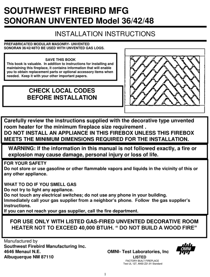
1. Remove the knockout indentation on the refractory (or firebrick) wall, located
approximately 2 inches above the refractory hearth floor. To remove, pry knockout
(inside fireplace) with a chisel, screwdriver or sharp object until knockout is released.
Use ¾“masonry drill bit to remove remaining firebrick. Remove fragmented portion of
refractory.
2. Remove gas line cover plane on right or left hand side of fireplace (depending on which
way incoming gas line is routed to the fireplace). Pull out insulation from gas line sleeve.
3. Run a 1/2-inch NPT black iron gas line into the fireplace 8 1/2 inches from the floor, and
route into the fire chamber through the gas line sleeve. (If using a raised platform, add
height of platform to specified 8 1/2 inches.) Provide sufficient gas line into fireplace
chamber
for fitting connection.
NOTE: Secure incoming gas line to wood framing to provide rigidity for threaded end.
4. Re-pack insulation around gas line and into sleeve openings. Seal any gaps between gas line and refractory knockout hole
with refractory cement or commercial furnace cement. Either install decorative gas appliance (per instructions included with
appliance) or cap off gas line.
CAUTION: All gas piping and connections must be tested for leaks after installation is complete.
With gas turned ON, apply a soap and water solution to all connections and joints. If bubbles appear, leaks can be detected and
corrected.
DO NOT USE AN OPEN FLAME FOR LEAK TESTING. DO NOT OPERATE ANY APPLIANCE IF A LEAK IS DETECTED.
The gas pipe is only intended for connection to a decorative gas appliance that 1) incorporates an automatic shut-off device, and
2) complies with the Standard for decorative gas appliances for Installation in Vented Fireplaces, ANSI Z21.60-1 990. The
gas pipe must be installed in accordance with the National Fuel Gas code, ANSI Z223.1-1992.
“CAUTION” WHEN USING THE DECORATIVE APPLIANCE, THE FIREPLACE DAMPER MUST BE SET IN
THE FULLY OPEN POSITION
Optional: OUTSIDE AIR KIT INSTALLATION
If necessary, installation of an outside air kit must be done during the rough framing of the fireplace.
Outside combustion air can be accessed through either an exterior wall, a vented crawl space, or
through a chase enclosure.
CAUTION: AIR INLET DUCTS MUST NOT TERMINATE IN ATTIC SPACE (#OAK)
Avoid installing outside air eyebrow in areas where inlet opening may
be blocked by snow, bushes, or other obstacles. The maximum
height of air inlet above platform of fireplace is 3 feet below the
termination gas outlet. For operating instructions, refer to owner's
manual.
COMBUSTIBLE AIR SYSTEM:
A. An optional outside combustion duct Part #OAK vent is available
from distributor. In new construction, the exterior wall vent cover can
be installed at the same time as the roof flashing. The vent may be
placed on either side of the wall and ran directly into the structure.
Place at least 12” above the floor. Using the vent as a template draw
a 4” circle, Cut out the circle and insert the wall vent. Secure 4, #8 x
1 1/2 hex head self-drilling screws. Vent must be within the fireplace


