SOUTHWEST MONSTER AR60 User manual
KK3 Chassis Assembly Instructions
AR60 FREESTYLERC
CLO

2
PART AR60 Kit Clod Kit FreestyleRC Kit
Chassis Plate 2 2 2
Battery Tray 1 1 1
Transmission Tray 1 1 1
Electronic Tray 2 2 2
Roll bars 2 2 2
85mm Crossmember 6 6 6
72mm Crossmember 2 2 2
Universal Block 8 8 8
Spacer (1/4”) 2 - 2
4-Link Kit 1 1 1
FreestyleRC Swaybar kit 1 1 1
Swaybar connector rods 4 4 4
Swaybar bushings 4 4 4
AR60 Shock Mount kit
Shock Plates
M3 X 20 Rounded Head Screw
M3 Nylon Locknut
Spacer (5/16”)
4
8
8
4
- -
Clod ual Shock Mount kit
ual Shock Plates
M3 X 20 Rounded Head Screw
M3 Nylon Locknut
Spacer (1/4”)
Spacer (5/16”)
-
4
8
8
4
4
-
M3 x 20 Rounded Head Screw 8 8 8
M3 x 16 Rounded Head Screw 12 16 12
M3 x 12 Rounded Head Screw 16 16 16
M3 x 8 Rounded Head Screw 16 16 16
M3 Nylon Locknut 16 20 16

KK3 Chassis Assembly Instructions
3
85mm Crossmember
72mm Crossmember
Electronic Tray
Transmission Tray
Swaybar Bushing
Roll Bar
Side Plate
Battery Tray
KK3 Chassis Assembly Instructions
4
Step 1: Crossmember and Transmission Tray Installation
•Loosely attach five 85mm crossmembers to one side using M3 screws.
•Attach transmission tray to one side using M3 screws and locknuts.
•Transmission tray is symmetric.
85mm Crossmember
Transmission Tray
M3x12
Screw
M3x16
Screw
KK3 Chassis Assembly Instructions
5
Step 2: Battery Tray Subassembly
•Attach four Universal Blocks to the battery tray using M3 screws.
•Battery tray can be setup for standard and shorty battery packs.
M3x8
Screw
Universal
Block
Step 3: Battery Tray Installation
•Loosely attach battery tray subassembly using M3 screws.
•Place tray in the location that suits your setup.
•Battery tray is handed and should be installed per image.
M3x8
Screw
Battery Tray
Sub-Assembly
SCS/AX10
Clod
FreestyleRC
Standard
Battery
Pack
Shorty
Battery
Pack
KK3 Chassis Assembly Instructions
6
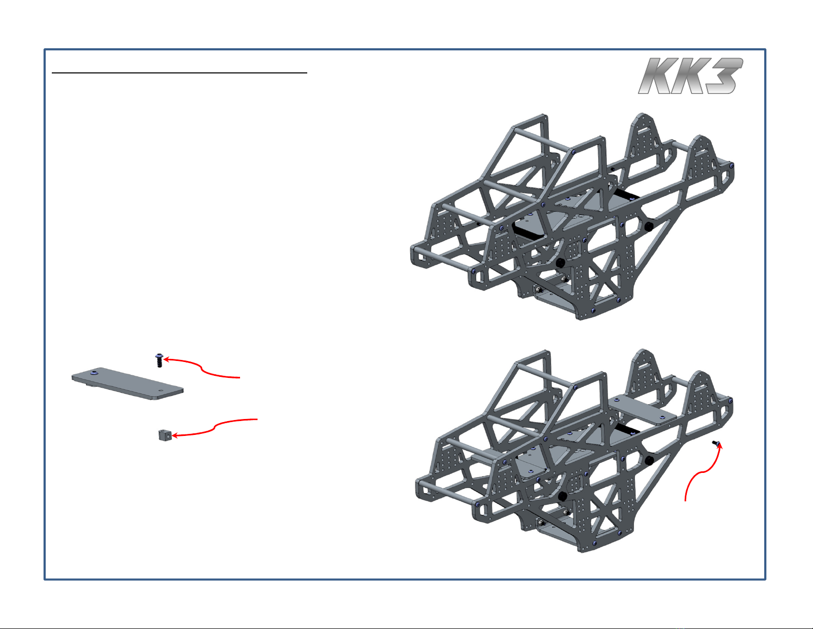
Step 4: Second Side Plate Installation
•Attach other side plate with M3 screws for crossmembers and
battery tray, and M3 screws and nuts for the transmission tray.
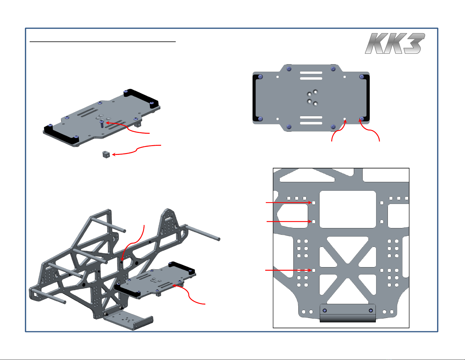
Step 5: Electronic Tray Subassembly
•Attach two Universal Blocks to each electronic tray using M3 screws.
•Build two electronic tray subassemblies.
M3x8
Screw
Universal
Block
Step 6: Electronic Tray Installation
•Attach electronic tray subassemblies to the main chassis
using M3 screws.
•The electronic trays are handed and should be assembled
with the undercut side touching the chassis rails.
M3x8
Screw

KK3 Chassis Assembly Instructions
7
Step 7: Roll bar Installation
•Roll bars can be installed in an up position or down position.
•Roll bars are handed. Refer to image for orientation.
•Up position requires cutting of the body to fit properly. This allows the roll
bars to be exposed through the body similar to full scale monster trucks.
•own position does not require cutting of the body to fit properly.
85mm Crossmember
Use M3x12 Screws
Rear Chassis Mount
Cab Mount
85mm Crossmember
Use M3x12 Screws
72mm Crossmember
Use M3x16 Screws
72mm
Crossmember
Use M3x16
Screws

8
KK3 Chassis Assembly Instructions
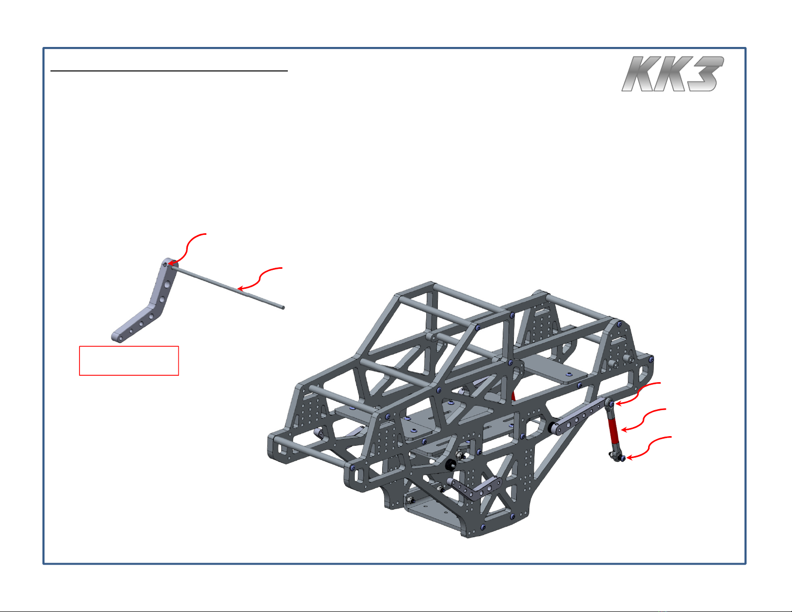
Step 8: 4-Link Installation
•Below are the hole-to-hole link lengths for each setup. Verify link lengths before proceeding.
Link AR60 Axles Clod Axles FreestyleRC Axles
Upper 125mm 138mm 118mm
Lower 118mm 118mm 138mm
Step 9: 4-Link Installation
•Identify connection points on the chassis.
•Mount upper links to the inside of the chassis.
•Lower Links may be mounted to the inside or outside of the
chassis per personal preference.
•All link to chassis connections use the following hardware.
Lower Links: AR60,
Clod, FreestyleRC
Upper Links: AR60,
Freestyle RC
Upper Links: Clod
M3x20
Screw
Locknut
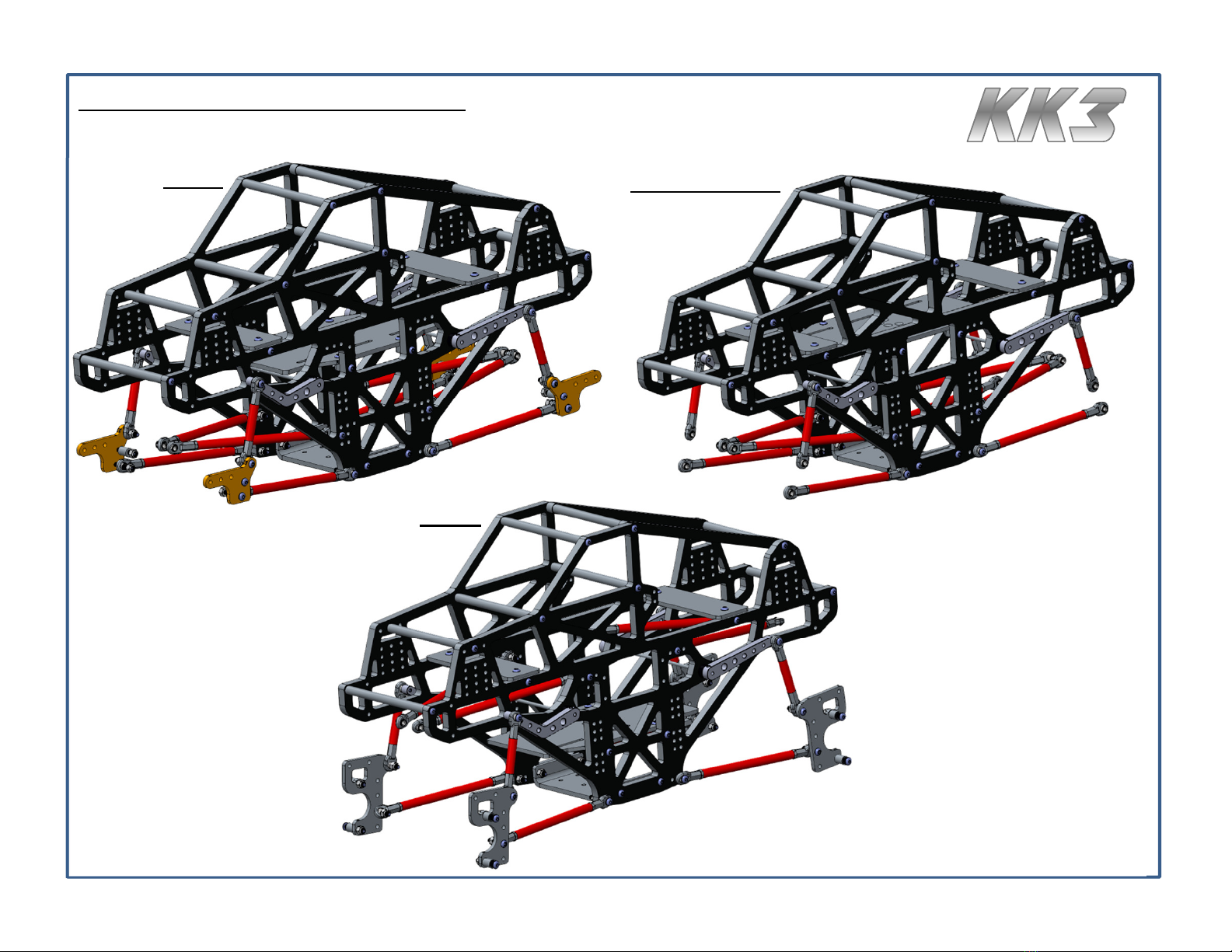
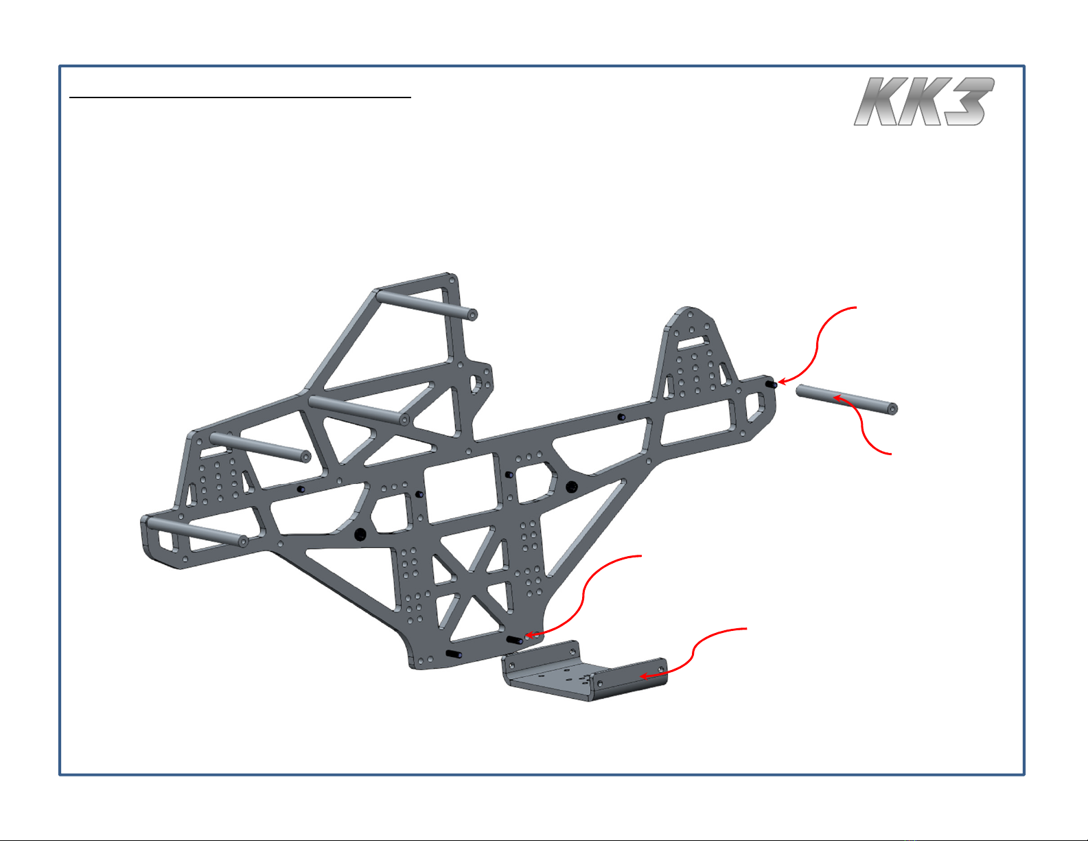
Step 10: Axle Shock Mount Setup
•The Clodbuster and AR60 chassis kits come with a dual shock kit.
•The FreestyleRC kit does not require a dual shock kit.
•The following two pages contain steps for dual shock kit installations.
Clod ual Shock Mount Instructions
Step 10.1:
•rill 1/8” hole in plastic axle tube. The shock bracket can be
used as a template to mark the lower hole.
Step 10.2:
•Slide axle metal brace though shock bracket and screw metal
brace to the main body of the axle case.
Step 10.3:
•Install short spacer on top by installing M3 screw and tightening
with the provided locknut.
•Repeat for bottom hole using the long spacer.
•Complete all installations.
rill Hole Use as drill template
M3x25 Screw M3 Locknut
Axle Mount
Spacer (LG)
Axle Mount
Spacer (SH) Axle Mount
Metal Brace
4-link holes
Shock holes
Swaybar hole

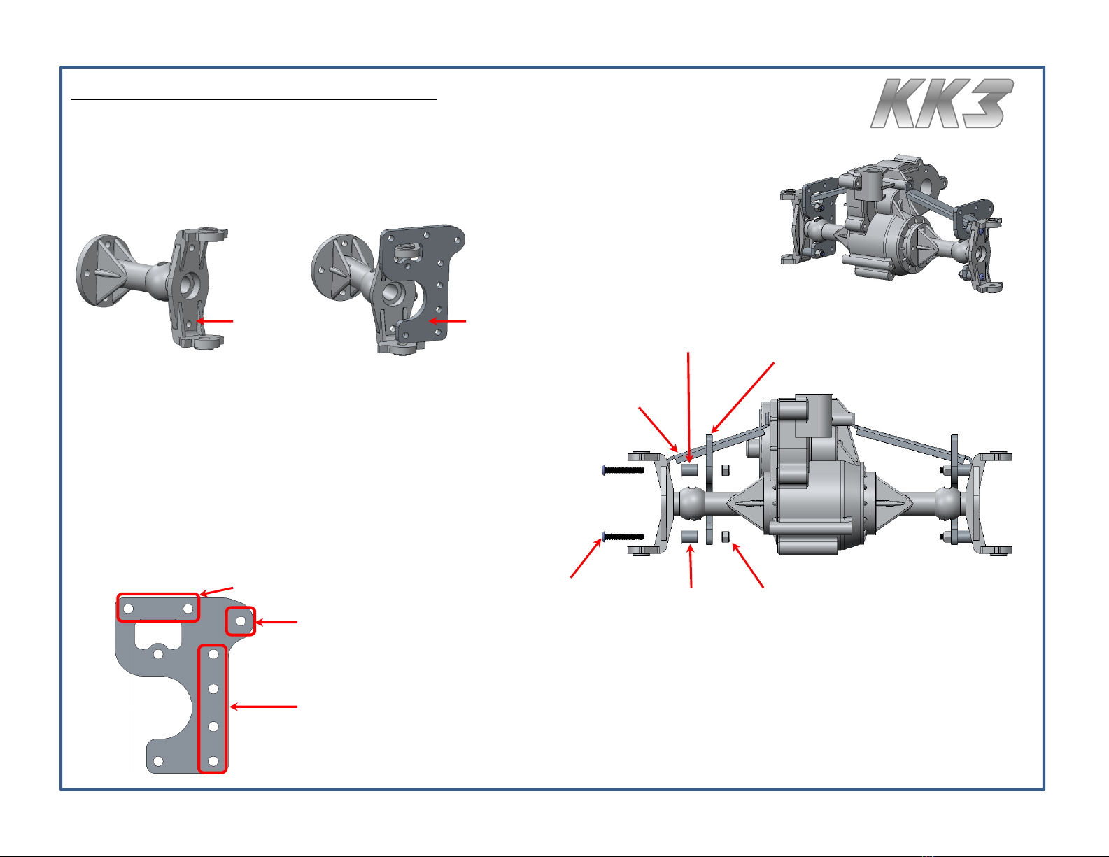
AR60 ual Shock Mount Instructions
Step 10.4:
•Install one dual shock bracket at a time. Place bracket on
outside of axle link mount.
Step 10.5:
•Insert screw through top bracket hole and through the axle link
mount. While sliding through, insert the 5/16” spacer and fasten
using a locknut.
Step 10.6:
•Insert bottom 4-link bar in lower location.
•Slide screw through the bottom bracket hole, 4-link rod end, and
axle link mount.
•Fasten using a locknut.
•Repeat for other side.
M3x20 Screw
(Qty 4) M3 Locknut
(Qty 4)
Spacer 5/16”
ual Shock
Bracket
4-link mount
Shock holes
Swaybar hole Axle Link
Mount
Swaybar Installation Instructions
Step 11:
•Remove set screw(s) from the swaybar arm, slide in torsion rod with flat spot oriented
towards the set screw(s). Apply blue thread locker to the set screw(s) and install tight.
•Slide swaybar and torsion rod through the bushings, and repeat the first bullet to install
the other swaybar arm.
•Use M3x12 screws to attach swaybar connector rods to the swaybar arms.
•Use M3x16 screws to attach swaybar connector rods to the dual shock kits for AR60 and
Clod setups.
Set Screw
M3x12
M3x16
*Swaybar image is for
referen e only
Torsion Rod
Connector Rod
12
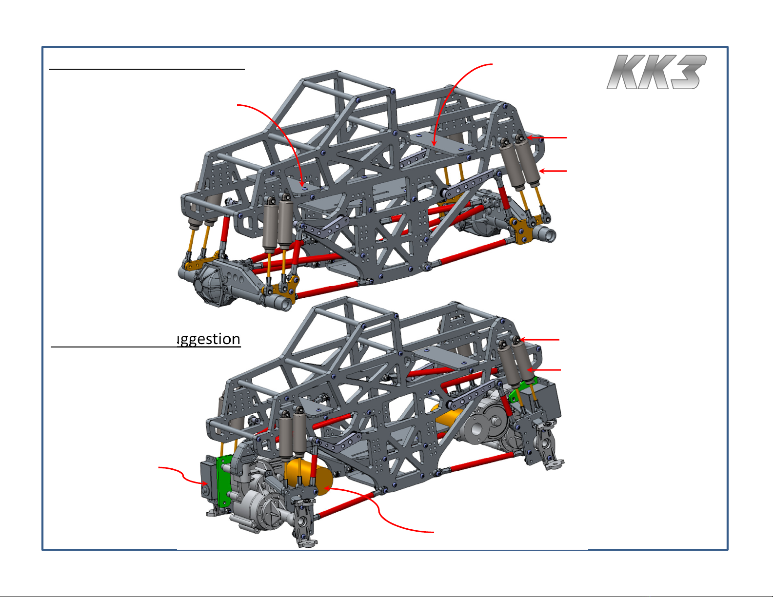
KK3 AR60 Setup Suggestion
4” Shocks
15wt oil
(1) shock w/spring and oil
(1) shock w/o spring and w/oil coating
4th Row Upper Connections
ESC/Receiver
ESC/Receiver
KK3 Clod Setup Suggestion
4” Shocks
15wt oil
(1) shock w/spring and oil
(1) shock w/o spring and w/oil coating
1st or 2nd Row Upper Connections
Brushless or Modified Brushed
540 sized motors only
Vertical servo
mount only

13
KK3 Center Transmission
FreestyleRC
Transmission
Mounting Holes
FreestyleRC
Transmission
Mounting Holes
SCS Transmission
Mounting Holes
SCS Mounting Holes
¼” Spacers
Note sensored
motor orientation
AX10 Holes
FreestyleRC SCS AX10
This manual suits for next models
2
Popular Toy manuals by other brands

PARKZONE
PARKZONE Vapor RTF instruction manual

The World Models Manufacturing
The World Models Manufacturing Katana EP instruction manual

Moni Toys
Moni Toys VENERA manual

MOB
MOB MO9187 user manual

Tiger Electronics
Tiger Electronics Head Start Computer NONE instructions

Elenco Electronics
Elenco Electronics SC-300 user guide


