Braemere Models GREAT BRITISH Smooth Sider Bulk Tipper Kit User manual


CLEAN ALL RESIN PARTS IN WARM SOAPY WATER
The silicone release agent used in the casng process will re-
act with paint, it must be thoroughly cleaned o before
painng.
1:32 Smooth-Sider Bulk
Tipping Trailer
This is a guide to using the kit. Care should be taken at each stage to make sure the model is
going together correctly and any alteraons that are not in the instrucons should be carried out.
Glue: Recommended glue is a good quality super glue such as Gorilla Super Glue. I use the Blue
Lid Gorilla Super Glue which is readily available from most hardware stores including B&Q and
Screwx. It provides a strong bond, the acrylic around the bond will snap before the bond breaks.
Paint: The instrucons will suggest the best point to paint components. A good quality
automove primer or plasc primer followed by automove acrylic is recommended. Brands
such as Hycote or Halfords are likely to be problem free and provide a good nish to your model
while being readily available.
Step 1: To start with I recommend cleaning
the resin parts (wheels and tyres) in a strong
washing up liquid soluon. Remove any ash
from the resin parts too, this is excess resin
le over from the casng process where res-
in is poured into the mould.
Then remove the plasc backing from all
acrylic parts and sand back the surface with a
ne grit sand paper 220 grit or less. The laser
cung process causes a slight raised edge on
most parts that will inhibit strong adhesion.
By sanding these edges o a stronger glued
bond can be made and the surface of the
plasc is improved for paint adhesion.
It is important to take care when sanding as
Acrylic is a brile material and can easily
snap. If something does break simply line up
the crack lines and glue back together, leave
24hrs before using the part again so the glue
can set rmly. The same applies to any resin
parts.

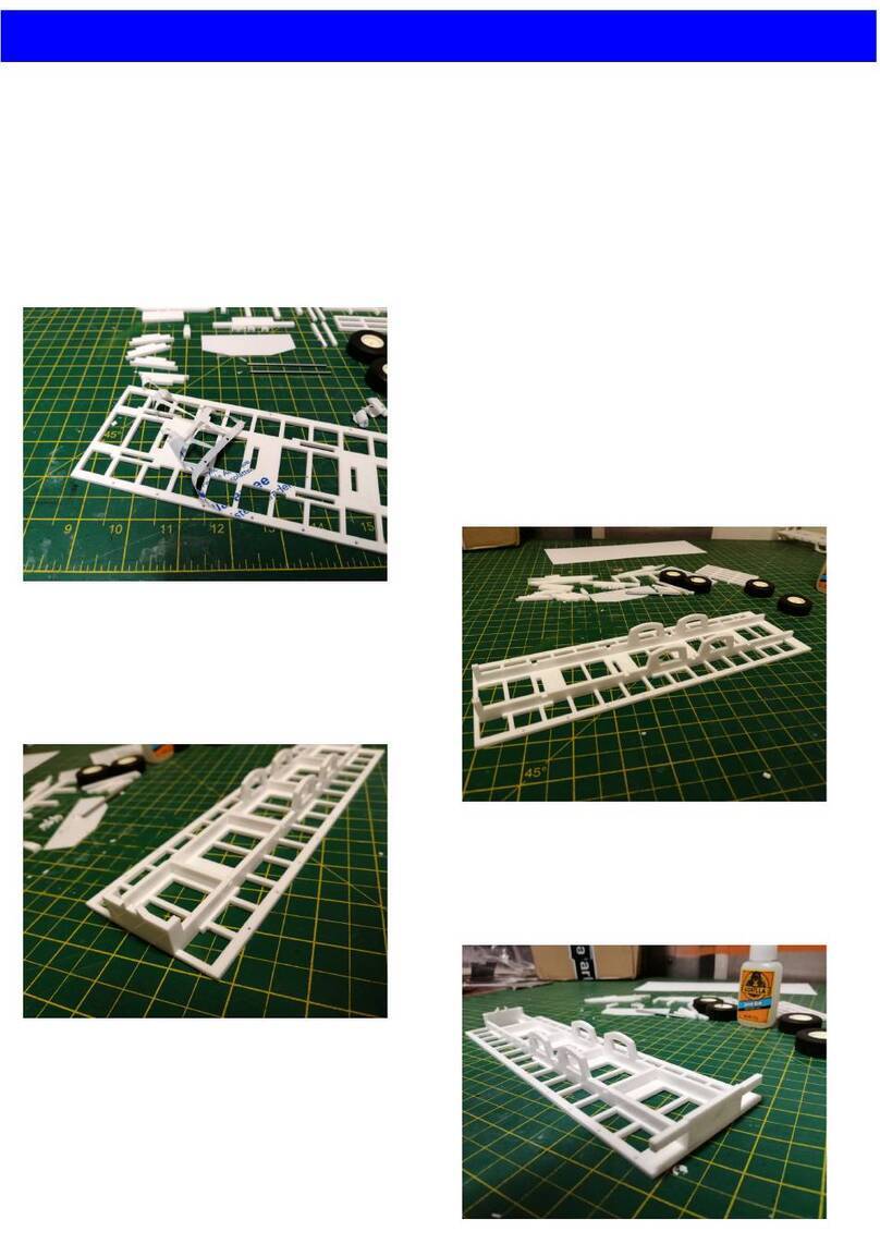
Step 2: Assemble the chassis rails
with the narrow 1mm clear
secons. The parts go together
as labelled below. Glue with one
end of the narrow strip at the
edge of the white acrylic part.
Make sure that this edge is
opposite for each side.
10
11
8
12
76

Step 3: Glue two pairs of part No.3 together
to double its thickness.
Step 4: Glue all cross members into their
slots in one chassis rail, gluing to the
opposite side of the rail to the overhanging
chassis rails.
Order from the front is 2 x No.2, 2 x pairs of
No.3 and 3x No.4 at the rear.
Ensure cross members are glued
perpendicular to the chassis rail.
Step 5: Glue the other chassis
rail to the other end of the
cross members. Ensure that
they straight and true

Step 6: The front of the chassis is
constructed with 1mm part No.15 at the
front and 2mm part No.16 behind to space
the chassis rails appropriately.
Step 7: Follow this by gluing the kingpin
plate to the boom of the front chassis. This
glues in place with the square hole at the
front. Refrain from gluing the kingpin in
place unl later when the best posioning
for your chosen tractor unit can be
determined.

Step 8: The rear end is assembled
with 1mm part No.14 glued at the
very back on the boom of the
chassis. Glued across the back of the
chassis is 2mm part No.18
Step 9: Moving to the top of the
chassis 1mm part No.15 is glued to
the back wrapping around the two
hinges, 1mm part No.13 then bridges
the sloped gap.

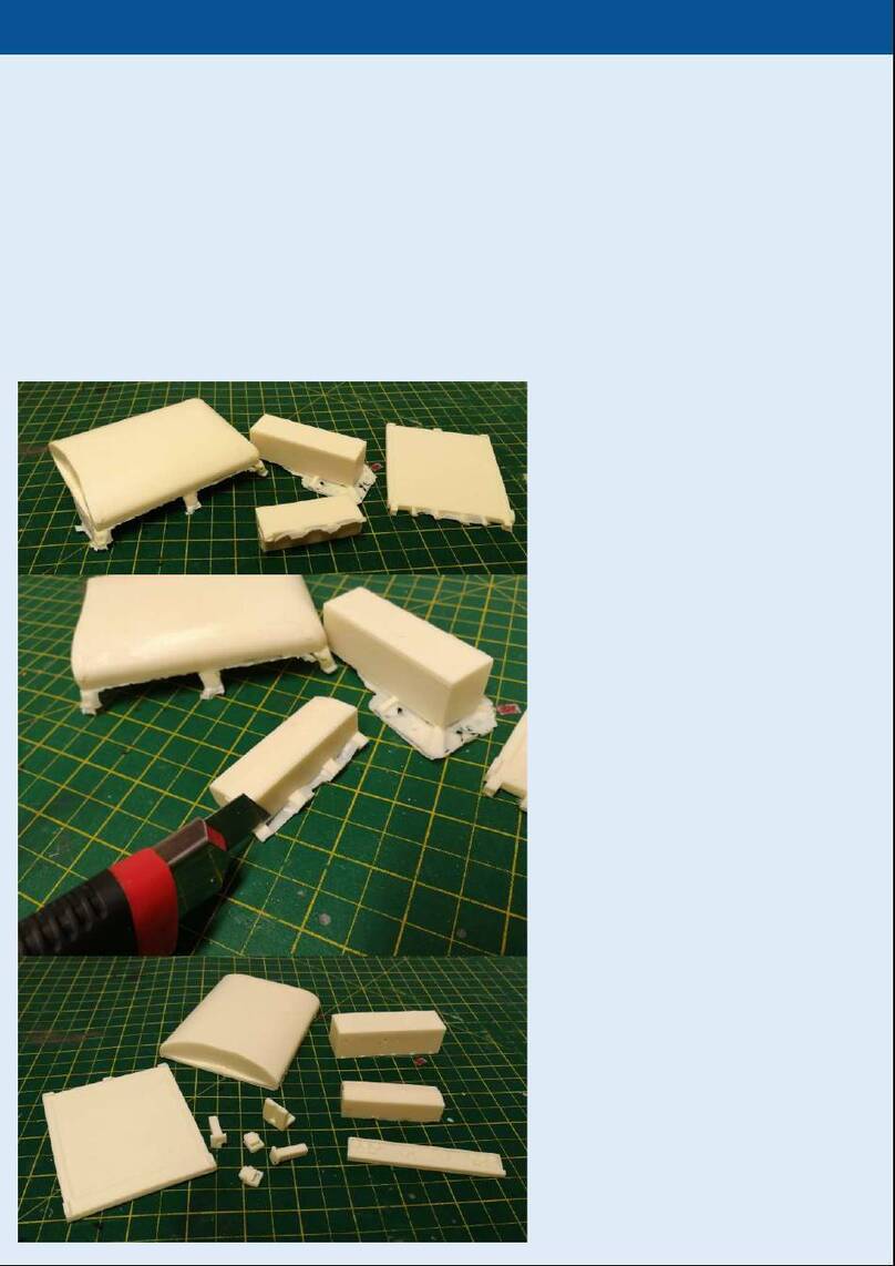
Step 10: Remove any ash from the
suspension casngs using a sharp knife
taking care not to break the resin parts.
Step 11: Glue the suspension casngs to the boom of the chassis. You may need to sand the top of the casng
to get the best t. When gluing ensure the casngs are running parallel with the chassis rails and that the holes
for the suspension line up allowing the axles to spin perpendicular to the chassis rails.

Step 12: Add the external details to the chassis. At the front there are two light stalks. At the step frame glue
the two jack legs to the chassis rails. Further back part No.19 slot into the chassis rails. These are the arms to
mount the cross members.
The side rails should be glued ush with the boom of their mounng brackets. They should be glued
extruding 8mm forward of the rst mounng bracket in order to accommodate the mudguards behind.

Step 13: If present remove the ash from the
mudguard casngs using a sharp knife taking care
not to break the casng.
Step 14: Glue the 6 rods into the holes in the chassis. They should be glued centrally with the same amount
extruding either side of the chassis.

Step 15: Work moves onto the body now. To begin with glue the oors together. Part No.51 and No.71 should
be glued aback to back, as should No.52 and No.70 along with No.53 and No.69.
Step 16: Glue the oors to one of the large trailer sides. Glue to the blank side with the engraved detail
poinng outwards. 51 & 71 ts to the back with the thick secon with small slots in at the back. 52 & 70 t in
the sloped secon and 53&69 t to the front with the large open slot poinng to the front.

Step 17: Glue the front to the
side with the engraved details
point out. Bridge the gap
between the front and the
oor using the two resin cast
triangular parts.
Step 18: Glue the ram supports to the inside of the body. The two part No.66 glue into the recesses at
the boom and should follow the gap in the front straight up. Cap them with the small unnumbered top
piece (14mmx10mm). And the slope is capped by part No.57.

Step 19: The other side can now be glued into place ensuring that all panels line up symmetrically.
Step 20: The sheet supports (part No.72) are next to be glued in place to provide rigidity to the body. Four in
total are posioned as below, one at the front, one centrally and two sandwiched together at the rear (inline
with the last engraved line.

Step 21: The front plaorm is the next part to be
assembled. The parts are very ne making them
delicate so take parcular care in assembly. Start by
gluing the plaorm frame No.61 into its two slots on
the front. From this the upright handle can be ed
slong into two slots on the front and nestling into
the notch in the plaorm frame.
Next add the front railings connecng to the two
notches and the steps to the upright handle. Add
the two corner pieces ed into the slots and
connect with the notches on the front railings.
Finally add the checkerplate oor, do not force the
oor into place, trim to size if necessary.

Step 22: The last steps with the body for
now are to add the underside details.
The hinges No.59 t into the slots at the
back of the trailer.
Just before the step in the body t the two
small squares that locate the body centrally
on the chassis when lowered. Finally add
the resin detail for the tailgate to the back,
this should bu up ush with the rear of
the oor.

Step 23: The rear door is built starng with the
back panel which is the clear 1mm piece with two
small hole sin the top corners and one larger hole
centrally at the boom.
Glue part No.57 to the top of this lining up the top
holes. Pre-paint the grain hatch lid (No.60) as it
will be dicult to paint later. Then rest it in the
channel of part 57.
Now glue the front onto No.57 trapping the hatch
lid inside. Make sure the engraved detail point
outwards.
Finally glue the hinges part No.58 into the back
via the slots.

Step 24: Now that the body and chassis can be aligned the mudguards can be glued into place. Apply glue to
the brackets on the resin parts and glue to the rods protruding from the chassis. Align the mudguards with the
edge of the body by laying the chassis on the body and making any adjustments necessary. If there are any
protrusions from the rods they can be trimmed o using nsnips once the glue has set. The rods can easily be
bent to meet with the brackets if the alignment is slightly out.
You may wish to leave this step unl aer the chassis is painted. The mudguards can easily be painted black
while the chassis is painted your desired colour. It may prove dicult to glue the mudguards in place aer
without leaving glue marks on the paint though. I have opted to glue them and then brush paint the
mudguards aer spray painng the chassis.

Step 25: The Bumper is constructed by
gluing the two part No.23’s to the back
of the chassis with the ns protruding
backwards. The bumper part No.24 can
then be glued onto the 23’s. Making
sure that it is aligned centrally with the
chassis.
Step 26: The light ngs can be glued
either side of the chassis behind the
bumper, try to t them as close to the
mudguards as possible so that they
don’t clash when pping the trailer.
Step 27: The toolbox and onboard
weigher can be glued to the right hand
chassis rail. Glue the tool locker back
from the cross member to avoid
clashing with the bump stops on the
body.

Step 28: You can now determine the kingpin posion depending on the tractor unit you want to use. For a
Welly Scania I recommend the centre hole. Glue the small 8mmx8mmx2mm square with a hole in the centre
over your chosen kingpin posion. The glue the 2mm plasc rod into the boom to form the kingpin.
Step 29: The mudguards Part No.74 Glue to the sides of the body. Mark a point 14mm from the rear most
point of the trailer side. Glue the mudguard lining up the top corner part to with the marked line.
14mm
14mm

Step 30: The sides to the mudguard Part No.76 are glued into place as photographed above. Take care with
the rear ones that they don’t clash with the light clusters on the chassis.
Step 31: Glue the three short 1.6mm stubs into the 3 holes on the right hand side of the trailer body. These
will secure the roll over sheet in place. For the best paint nish remove the green paper outer covering.

Step 32: The parts are now ready for paint. I would recommend starng with a plasc primer, I used Halfords
Grey Plasc Primer. This helps bond to the acrylic parts while also levelling everything to the same colour, it is
also opaque enough to block light shinning through the clear plasc parts. Once the primer is dry I have used
an Aluminium Eect Spray Paint from Hycote for the body (a silver automove paint such as Halfords is also
suitable). Automove paint has also been used to paint the chassis. In this case Halfords Peugeot Cherry Red.
Once dry details can be brush painted in such
as painng the mudguards, air bags and tool
locker in ma black, and the crash rails in
silver.
Other Braemere Models Toy manuals
