Southwestern Industries TRAK LPM Mounting instructions

TRAK®LPM
Service, Safety, Installation, Maintenance and Parts List
Document: P/N 26727
Version: 051013
Southwestern Industries, Inc.
2615 Homestead Place
Rancho Dominguez, CA 90220-5610 USA
T | 310-608-4422 |F | 310-764-2668
Service Department: 800.367.3165
e-mail: sales@southwesternindustries.com | service@southwesternindustries.com | web: southwesternindustries.com

Copyright 2013, Southwestern Industries, Inc. All rights are reserved. No part of this
publication may be reproduced, stored in a retrieval system, or transmitted, in any form or by
any means, mechanical, photocopying, recording or otherwise, without the prior written
permission of Southwestern Industries, Inc.
While every effort has been made to include all the information required for the purposes of this
guide, Southwestern Industries, Inc. assumes no responsibility for inaccuracies or omission and
accepts no liability for damages resulting from the use of the information contained in this guide.
All brand names and products are trademarks or registered trademarks of their respective holders.

i
Southwestern Industries, Inc.
TRAK
LPM Installation, Maintenance, Service, & Part List Manual
Table of Contents
1.0 Safety
1.1 Safety Publications 1
1.2 Danger, Warning, Caution and Note
Labels and Notices Used in this Manual
1.3 Safety Precautions
2.0 System Description
2.1 Machine Specifications 8
2.2 Maximum Spindle Torque & HP
2.3 ProtoTRAK PMX Control Hardware
2.4 Machine Major Subassemblies
3.0 Installation
3.1 Lifting & Placing the LPM 17
3.2 Leveling Screw Locations
3.3 Uncrating the LPM
3.4 Shortages: Inventory Checklist
3.5 Installation Checklist
3.6 Electrical Connections
3.7 Air Connections
3.8 Placing the Coolant System
3.9 Cleaning the LPM
3.10 Leveling Procedure
3.11 Lubrication
3.12 Cutting a Euclid Block
3.13 Indexer Installation
4.0 Troubleshooting by Symptom
4.1 Machining Problems 42
4.2 Motion Related Problems
4.3 Control Related Problems
4.4 Tool Changer or Loading & Unloading Tools from
Spindle Problems
4.5 Control Input or Output Problems
4.6 Measurement Problems
4.7 Machine Tool Problems
5.0 Diagnostics
5.1 The Machine Tool & Setup 74
5.2 The Mechanical Drive Train
5.3 Computer Module Diagnostics
5.4 Pendant
5.5 Motors Diagnostics
5.6 Axis & Spindle Drives
5.7 Electrical
5.8 Digital Input/Output Diagnostics
5.9 Tool Changer Diagnostics
5.10 Pneumatic Diagnostics
5.11 Coolant Diagnostics
5.12 Service Codes
6.0 Replacement Procedures
6.1 Servo Replacement 144
6.2 Servo Driver Replacement
6.3 AC Spindle Replacement
6.4 Computer Module Replacement
6.5 Compact Flash Replacement
6.6 Cable Routing in Electrical Box
6.7 Linear Guide Replacement
6.8 Ballsrew Replacement-X Axis
6.9 Ballsrew Replacement-Y Axis
6.10 Ballsrew Replacement-Z Axis
6.11 Angular Contact Bearing Replacement
6.12 Spindle Motor Replacement
6.13 Spindle Motor Wiring
6.14 Spindle Cartridge Replacement
6.15 Tool Clamp Mechanism Replacement
6.16 Automatic Tool Changer (ATC) Replacement
6.17 Coolant Pump Replacement
6.18 Pneumatic Part Replacements
6.19 Auger Motor Replacement
6.20 Programming and Run Panel Replacement
6.21 Limit/Home Switch Replacement
7.0 Maintenance
7.1 Laser Calibration 191
7.2 Backlash Compensation
7.3 Limit Switch Adjustments
7.4 Periodic Maintenance
8.0 4th Axis 196
8.1 4th Axis Specifications
8.2 Mounting 4th Axis
8.3 Installation Checklist of the 4th Axis
8.4 Air Connection
8.5 Lubrication
8.6 4th Axis Specific Service Codes
8.7 Troubleshooting by Symptom
8.8 Replacement Procedures
Assembly Drawings (rear of manual)
System Diagram – 26734 Rev C
X Axis Drive Train – 26772 Rev A
Y Axis Drive Train – 26817 Rev A
Z Axis Drive Train – 26756 Rev –
Pendant Assembly – 26584 Rev –
ATC Assembly – Lower – 26784 Rev A
ATC Assembly – Upper – 26811 Rev –
ATC Adjustment Points – 26966 Rev –
Head Assembly – 26854 Rev C
Spindle Cartridge Assembly – 26848 Rev –
Pneumatic System – 26930 Rev B
Coolant System – 26943 Rev D
Lubrication System – 27050 Rev A
Limit Switch Assembly – 26827 Rev –
Electrical Enclosure Assembly – 26571 Rev K
Enclosure Assembly – 26862 Rev E
Machine Casting Assembly – 26910 Rev –

ii
Southwestern Industries, Inc.
TRAK
LPM Installation, Maintenance, Service, & Part List Manual
Cable Carrier Assembly & Shipping Brackets – 26900 Rev A
Gage Assembly-Tooling Setting – 26534 Rev D
Transformer Option-440V – 26939 Rev C
Schematic-Electrical – 26775-SCH Rev D
4TH Axis Option-8” CNC-200RB –27066-4 Rev –
Rotary Table Assembly-8” CNC-200RB – 27065-2 Rev –
4TH Axis Option-8” SWI – 27066-6 Rev –
4TH Axis Assembly-8” SWI – 28060 Rev –`

1
Southwestern Industries, Inc.
TRAKLPM Installation, Maintenance, Service, & Part List Manual
1.0 Safety
The safe operation of the LPM depends on its proper use and the precautions taken by each
operator.
•Read and study this manual and the LPM Programming, Operating, and Care Manual. Be
certain every operator understands the operation and safety requirements of this
machine
before
its use.
•Never run the machine with enclosure doors open
•Always wear safety glasses and safety shoes.
•Always stop the spindle and check to ensure the CNC control is in the stop mode before
changing or adjusting the tool or workpiece.
•Never wear gloves, rings, watches, long sleeves, neckties, jewelry, or other loose items
when operating or around the machine.
•Use adequate point of operation safeguarding. It is the responsibility of the employer to
provide and ensure point of operation safeguarding per OSHA 1910.212 -Machining
centers.
1.1 Safety Publications
Refer to and study the following publications for assistance in enhancing the safe use of this
machine.
Safety Requirements for Machining Centers and Automatic, Numerically Controlled
Milling, Drilling and Boring Machines (ANSI B11.23-2002) (R2007). Available from The
American National Standards Institute, 1819 L Street N.W., Washington D.C. 20036
Concepts And Techniques Of Machine Safeguarding (OSHA Publication Number 3067).
Available from The Publication Office - O.S.H.A., U.S. Department of Labor, 200 Constitution
Avenue, NW, Washington, DC 0210.
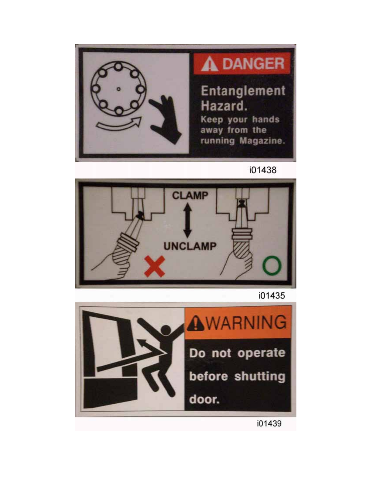
1.2 Danger, Warning, Caution, and Note Labels & Notices
As Used In This Manual
DANGER - Immediate hazards that will result in severe personal injury or death. Danger labels
on the machine are red in color.
WARNING - Hazards or unsafe practices that
could
result in severe personal injury and/or
damage to the equipment. Warning labels on the machine are orange in color.
CAUTION - Hazards or unsafe practices, which
could
result in minor personal injury or
equipment/product damage. Caution labels on the machine are yellow in color.
NOTE - Call attention to specific issues requiring special attention or understanding.
HELPFUL TIP- A technique or tool that can aid you.

2
Southwestern Industries, Inc.
TRAKLPM Installation, Maintenance, Service, & Part List Manual
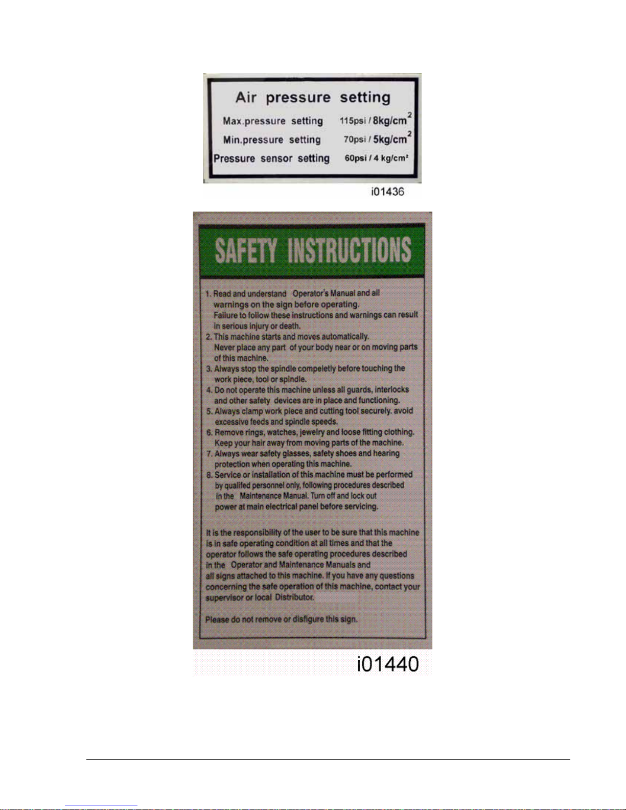
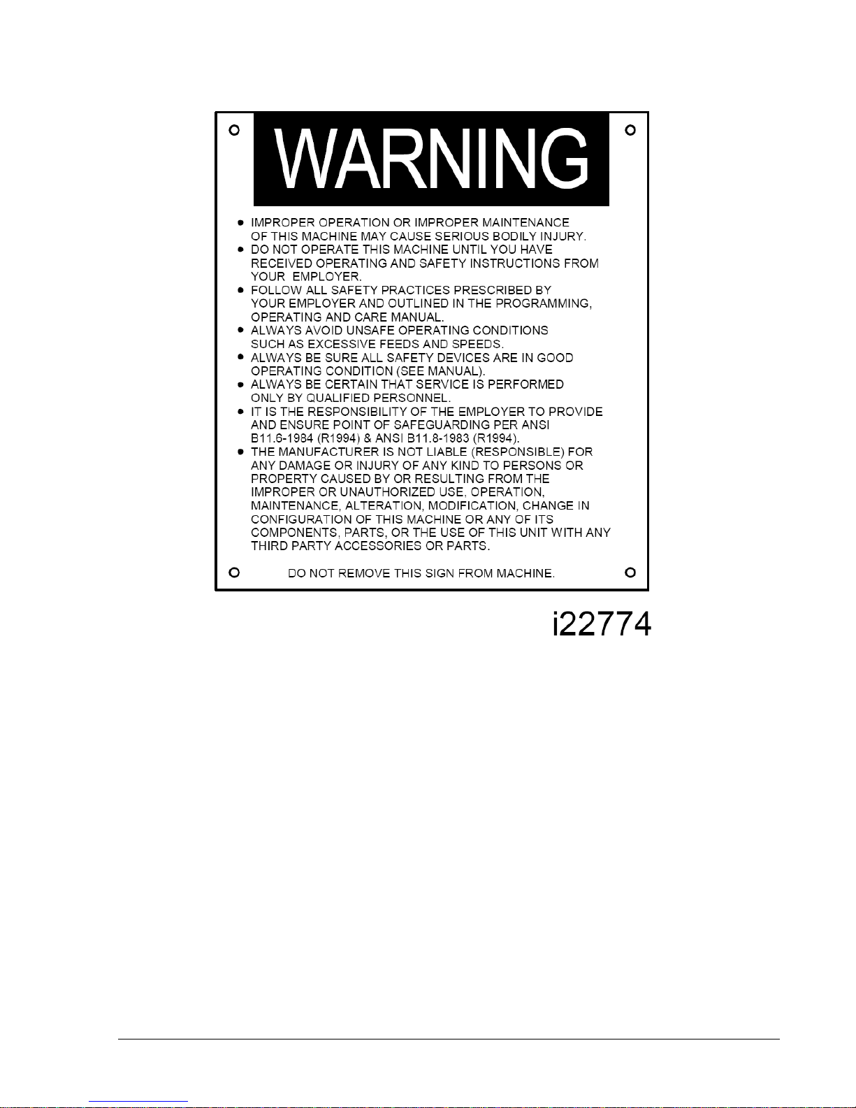
Safety & Information Labels Used On The
LPM Milling Machine
It is forbidden by OSHA regulations and by law to deface, destroy or
remove any of these labels
3
Southwestern Industries, Inc.
TRAKLPM Installation, Maintenance, Service, & Part List Manual
4
Southwestern Industries, Inc.
TRAKLPM Installation, Maintenance, Service, & Part List Manual
5
Southwestern Industries, Inc.
TRAKLPM Installation, Maintenance, Service, & Part List Manual

6
Southwestern Industries, Inc.
TRAKLPM Installation, Maintenance, Service, & Part List Manual
1.3 Safety Precautions
1. Do not operate this machine before the LPM Installation, Maintenance, Service and
Parts List Manual,Operating & Care Manual have been studied and understood.
2. Do not run this machine without knowing the function of every control key, button, knob,
or handle. Ask your supervisor or a qualified instructor for help when needed.
3. Protect your eyes. Wear approved safety glasses (with side shields) at all times.
4. Don't get caught in moving parts. Before operating this machine remove all jewelry
including watches and rings, neckties, and any loose-fitting clothing.
5. Keep your hair away from moving parts. Wear adequate safety headgear.
6. Protect your feet. Wear safety shoes with oil-resistant, anti-skid soles, and steel toes.
7. Take off gloves before you start the machine. Gloves are easily caught in moving parts.
8. Remove all tools from the machine before you start. Loose items can become dangerous
flying projectiles.
9. Never operate a milling machine after consuming alcoholic beverages, or taking strong
medication, or while using non-prescription drugs.
10. Protect your hands. Stop the machine spindle and ensure that the CNC control is in the
stop mode:
•Before changing tools
•Before changing parts
•Before you clear away the chips, oil or coolant. Always use a chip scraper or brush.
•Do not used compressed air to clean the machine.
•Before you make an adjustment to the part, fixture, coolant nozzle or take
measurements.
•Do not attempt to disable any safety interlock. Never reach around a safeguard.
11. Protect your eyes and the machine as well.
12. Disconnect power to the machine before you change belts, pulley, and gears.
13. Keep work areas well lighted. Ask for additional light if needed.
14. Do not lean on the machine while it is running.
15. Prevent slippage. Keep the work area dry and clean. Remove the chips, oil, coolant and
obstacles of any kind around the machine.
16. Avoid getting pinched in places where the table, saddle or spindle head create "pinch
points" while in motion.
17. Securely clamp and properly locate the workpiece in the vise, on the table, or in a fixture.
Use stop blocks to prevent objects from flying loose. Use proper holding clamping
attachments and position them clear of the tool path.
18. Use correct cutting parameters (speed, feed, depth, and width of cut) in order to prevent
tool breakage due to premature wear.

7
Southwestern Industries, Inc.
TRAKLPM Installation, Maintenance, Service, & Part List Manual
19. Use proper cutting tools for the job. Pay attention to the rotation of the spindle: As
viewed from above, left hand tool for counterclockwise rotation of spindle, and right
hand tool for clockwise rotation of spindle.
20. To prevent damage to the workpiece or the cutting tool, never start the machine
(including the rotation of the spindle) if the tool is in contact with the part.
21. Check the direction (+ or -) of movement of the table when using the jog feature,
clockwise rotation of the EHW moves the axis in the positive direction, counterclockwise
in the negative direction.
22. Don't use dull or damaged cutting tools. They break easily and become airborne.
Inspect the sharpness of the edges, and the integrity of cutting tools and their holders.
Use proper length for the tool.
23. Inspect the retention knobs for damage or excessive wear before each use.
24. Large overhang on cutting tools when not required result in accidents and damaged
parts.
25. Prevent fires. When machining certain materials (magnesium, etc.) the chips and dust
are highly flammable. Obtain special instruction from your supervisor before machining
these materials.
26. Prevent fires. Keep flammable materials and fluids away from the machine and hot,
flying chips.
Warning
Retention knobs come in a wide variety of designs, however they often look similar and appear to
be interchangeable, but they are not. Use only the knob that the LPM is designed to use. The use
of the incorrect knob, or the incorrect usage of a knob, may result in injury or property damage.
To ensure the correct knob is chosen, please refer to section 2.4.4, Machine Major
Subassemblies section of this manual

8
Southwestern Industries, Inc.
TRAK
LPM Installation, Maintenance, Service, & Part List Manual
2.0 System Description
Read and understand this entire installation section before beginning the installation procedure.
2.1 Machine Specifications
Please see the drawing on the next page for a layout of the LPM machine.
Overall Machine Dimensions
Width of LPM without chip cart and auger chute 89.75”
Depth of LPM 88”
Height of LPM with head all the way up 103”
Width of LPM with chip cart and side doors open 157”
Minimum height to fit LPM through doorway 85”
(Z cable carrier collapsed)
Minimum doorway width or height the LPM can fit through is 88” x 85” (assumes Z cable carrier
collapsed and Z axis motor removed). The 85” dimension can be reduced to 82” if further items
are removed or adjusted.
Machine Specifications
Table Dimensions
Table size 35.38” X 19.63”
Number of tee slots and pitch 5 @ 100 mm
Tee slot width 0.710” or 18 mm
Table maximum load 1000 lbs.
Ball Lock ® hold down force 2250 lbs @ 35 in/lbs of torque
Travel
X-axis 31”
Y-axis 18.5”
Z-axis 21”
Maximum distance from spindle nose table surface
24”
Minimum distance from spindle nose table surface
3.375”
Maximum swing clearance from spindle center to column
19.25”
Maximum Rapid speed X & Y-axis, inches per minute
800
Maximum Rapid speed Z-axis, inches per minute
700
Spindle
Tool holder type CAT40
Spindle nose diameter 2.75
Maximum RPM 8000
Automatic Tool Changer
Tool Capacity 16
Maximum tool weight including holder 15 lbs
Maximum tool diameter
3.14
Carousel speed
.8 sec from station to station
Tool selection system
Bi-directional/ shortest path
Retention knob
See section 2.4.4
Air Requirements
Pressure CFM or SCFM 90 psi 2.5 or 18 at 90 psi
Quality Air dried/ water separator upstream of
the LPM

9
Southwestern Industries, Inc.
TRAK
LPM Installation, Maintenance, Service, & Part List Manual

10
Southwestern Industries, Inc.
TRAK
LPM Installation, Maintenance, Service, & Part List Manual
2.2 Maximum Spindle Torque and Horsepower
The following graphs illustrate the continuous and peak torque vs RPM and horsepower vs RPM
for the LPM machine at the spindle. Peak torque and horsepower values can only be attained for
a short period of time before the spindle drive will fault out to protect the motor.
Note - Maximum work capacities are dependent on a lot of variables that cannot be controlled by
the machine manufacturer. Each one of the following will have an impact on the above
numbers: speeds, feeds, cutter, cutter sharpness, material, setup, coolant and machine
adjustments.
0
10
20
30
40
50
60
-2000 3000 8000
Torque (ft-lbs)
RPM
Torque vs RPM
Continuous Torque
Peak Torque
0
2
4
6
8
10
12
14
16
0 2000 4000 6000 8000
HP
RPM
HP vs RPM
Continuous HP
Peak HP

11
Southwestern Industries, Inc.
TRAK
LPM Installation, Maintenance, Service, & Part List Manual
2.3 ProtoTRAK PMX Control Hardware
2.3.1 Pendant Assembly
The pendant assembly on the LPM is the sheet metal control box that sits in the upper right hand
corner of the machine. The pendant assembly contains the program panel, run panel, 4 USB
ports and a servo on button and cable. The pendant assembly can rotate and sit at a 45 or 80
degree angle or sit flush with the machine. See drawing 26584 at the rear of the manual.
2.3.1.1Program Panel
The program panel is the upper panel found on the LPM pendant assembly. The
program panel is where the user enters all the associated information when creating,
setting up and running a program.
The program panel consists of the program overlay and a 12.1” LCD. At the rear of the
assembly the VGA cable connects to the back of the assembly and routes back to the
electrical box. The VGA cable carries video signals from the computer module to LCD
controller board. There are also 3 local cables that route between the LCD and
associated boards. They are the LCD inverter power, LCD user interface and LCD power
cables.
2.3.1.2Run Panel
The run panel is the lower panel found on the LPM pendant assembly. The run panel is
where the user is able to turn the spindle on, move the machine around with the
electronic handwheels, control the spindle and feed overrides and where various outputs
can be turned on or off. Things like the coolant pump, auger, etc.
The run panel consists of the run overlay, electronic handwheel and E-stop switch. At
the rear of the assembly there are 6 cables that connect to the back of the assembly and
route back to the electrical box. They are the COM port cable, handwheel cable, USB
cable, E-stop cable, overlay power cable and ground wire.
The COM cable communicates between computer module and overlay interface board.
2.3.2 Electrical Cabinet
The electrical cabinet is found at the rear of the LPM on the right side. The electrical cabinet
contains the main control hardware for the machine. The main components are as follows:
computer module, AC spindle drive, servo drives, input/output modules, relays and contactors.
See drawing 26571 at the rear of the manual.
2.3.3 Computer Module
The computer module is the heart and soul of the machine. All of the inputs and outputs are fed
through this module. The computer module controls the program panel, run panel, AC spindle
drive, servo drives, motor signals and feedback and input/output modules. Inside of the
computer module is a motherboard, motion control board and an applications board along with a
power supply.

12
Southwestern Industries, Inc.
TRAK
LPM Installation, Maintenance, Service, & Part List Manual
The computer module also contains 4 more USB ports and a network port. We ship the machine
with 3 USB ports having something plugged into them. The 3 USB ports contain the following:
machine option key, a D drive for part storage and an overlay interface USB cable. The network
port is available to the user if they want to network the control to an offline computer or
network.
2.3.4 Servo Motors
The LPM can run up to 4 axis motors. The 4th motor would be used to control a 4th axis indexer.
The motors used on the X and Y axis are rated for 5.7 N-m of torque. The Z axis motor is rated
at 11 N-m and also contains a mechanical brake that holds the head in position when the power
is turned off to the machine.
2.3.5 Servo Drives
The LPM can also contain up to 4 servo drives. The 4th servo drive would be used to control a 4th
axis indexer. The servo drives receive signals from the computer module which in turn send
signals to the servo motors. The X and Y axis servo drives are identical and the Z axis and 4th
axis servo drives are programmed differently for their unique application so this means that only
the X and Y axis are interchangeable.
2.4 Machine Major Subassemblies
2.4.1 Spindle
The spindle is contained within a cartridge and CAT 40 tool holders must be used. The spindle
bearings are permanently lubricated and require no additional attention by the user. The spindle
is also air cooled, and has an air purge system that is automatically activated during the tool
change sequence, it blows air down the spindle to prevent chips from being trapped between the
holder and spindle taper.
2.4.2 Spindle Motor & Drive
The spindle motor is 10 HP and drives the spindle via a timing belt. The ratio between the
spindle and spindle motor is 1 to 1. The RPM range for this machine is 150 to 8000 RPM.
2.4.3 Automatic Draw Bar Assembly
The automatic drawbar is an assembly consisting of an air cylinder and an actuator that
unclamps the tool. Tooling is changed by means of the Automatic Tool Changer (ATC), or can be
done manually by pressing and holding the “Unclamp” button. Tools are clamped when the
button is released. A clamping force of approximately 1500 lbs is generated to clamp the
toolholder to the spindle. The Automatic Draw Bar Assembly uses full system air and requires no
adjustment. The air cylinder that does the clamping and unclamping is lubricated with a small
cup. Make sure to check the oil level in this cup on a regular basis.
2.4.4 Retention Knobs
The LPM uses CAT40 retention knobs as shown in Figure 2.4.4a. Tightening to the proper torque
value is important for all retention knobs. Please see the retention knob manufacturer for the
Warning!
The spindle unit is not field serviceable. If the bearings go bad the entire
spindle cartridge will be replaced.

13
Southwestern Industries, Inc.
TRAK
LPM Installation, Maintenance, Service, & Part List Manual
proper torque. You can order these retention knobs from Southwestern Industries under part
number 26800-2.
Figure 2.4.4a
Warning!
Retention knobs come in a wide variety of designs, however they often look similar and appear to
be interchangeable, but they are not. Use only the knob that the LPM is designed to use. The use
of the incorrect knob, or the incorrect use of a knob, may result in injury and/or damage to the
mechanism.
2.4.5 Tool Changer
The tool changer is an armless carousel type automatic tool changer that has a capacity of 16
tools. The carousel is mechanically indexed by means of a Geneva mechanism. The position of
the carousel is controlled by a signal from Home Position Sensor. As an additional safety feature,
the ATC also has Tool Detect Sensor at the “ready position”. This means if a tool is sitting in this
position and the control tries to put the tool in the spindle into this spot, an error will be
generated by the control.
2.4.6 Drive Train, Axes
Each axis (X, Y and Z) rides on precision linear guideways, with four preloaded recirculating ball
carriages. Each axis is moved via an 8 mm pitch ballscrew. The axis motors direct drive the
ballscrew.
2.4.7 Worktable
The LPM table utilizes Ball Lock® technology as well as conventional T-bolt construction. Each
Ball Lock mechanism has a hold-down force of 2250 lbs when 35 in/lbs of torque is applied to the
screw. The software on the LPM is based on these ball locks as we ask the user which ball lock
location they wish to run the part on. The 3 locations are called ball lock A, B and C. The
distance between ball locks A, B and C are approximately 7.829”.

14
Southwestern Industries, Inc.
TRAK
LPM Installation, Maintenance, Service, & Part List Manual
Figure 2.4.7a
2.4.8 Limit/Home switches
Each axis has a limit switch, which serves two purposes, to protect the LPM in the event of an
over-travel situation in either the positive or negative direction, and secondly for the purpose of
homing the machine. The following table describes where the cams are that trigger the limit
switches.
Table - Limit Switch Cam Locations
Axis End
Location of Cam Bracket
Cam Location
X-axis Negative End Left hand side of the table (front) Upper channel
X-axis Positive End Right hand side of the table (front) Lower channel
Y-axis Negative End
On the base casting, beneath the saddle (back)
Upper channel
Y-axis Positive End On the base casting, beneath the saddle (front) Lower channel
Z-axis Negative End
On the column casting (upper)
Right hand channel
Z-axis Positive End On the column casting (lower) Left hand channel
ATC Home Position
Sensor
ATC shroud
Target bolt on the
carousel
ATC Sliding Body,
home Bracket-Sliding Body Support, left Sliding Body
ATC Sliding Body,
Advanced Bracket-Sliding Body Support, right Sliding Body
Warning
It is not recommended that the position of the limit switches be changed. They are preset at the
factory and should require no additional adjustments. Should any major adjustments be done,
service code 500, 505 and/or 501 and 502 may need to be performed.

15
Southwestern Industries, Inc.
TRAK
LPM Installation, Maintenance, Service, & Part List Manual
2.4.9 Lubrication System
The automatic lubricating system is a centralized system. It is located at the rear of the machine.
While the system is automatic, it is recommended that after long idle periods, the machine be
manually lubricated by pressing, holding (about five seconds) until the system is charged, then
releasing the square green button located on the lubricator, repeat two to three times. The
lubricating system delivers 2 shots of oil when the machine is turned on at the disconnect switch,
and 1 shot every 30 minutes of axis motion. Each shot provides 2.7 ml of oil. The lubrication
reservoir should be maintained on a daily basis, filling only with high quality lubricating oil. All
pneumatic components are lubricated by means of an inline oiler. See section 3.11
2.4.10 Coolant and Coolant Wash System
The coolant and coolant wash system uses two pumps, one for providing coolant to the work,
and the other for washing the chips into the auger. Wash areas can be controlled by the flexible
coolant lines found at the base of the enclosure, both left and right-hand sides. Coolant wash can
also be done with the use of the hose and nozzle found on the front exterior of the enclosure.
The coolant pump must be turned on for this hose to work. We recommend you close the
coolant pump hoses at the spindle to provide the most pressure to the hose.
The coolant tank holds approximately 55 gallons of coolant.
See drawing 26943 at the rear of the manual for the coolant system.
2.4.11 Pneumatic System
The machine requires a supply of compressed air between 85-100 psi with a recommended air
supply of ½” I.D. Air pressure to pneumatic components, the ATC slide mechanism, air blast and
air purge (internal spindle) can be controlled individually by means of the adjusting valves
located at the back of the LPM. See drawing 26930 for an overview of the pneumatic system.
2.4.12 Enclosure Doors
The front door has an electro-mechanical safety interlock that must be engaged when running a
CNC program. If the door is opened during a machining operation, the program will be shut
down.
The enclosure is also equipped with left and a right latched and lockable access doors.
2.4.13 Beacon Lights
The machine has a beacon light attached to the top of the machine to give the user status of
what is going on. The lights perform as follows:
a. The green light is illuminated when the machine is running a program.
b. The yellow light is illuminated when operator input is required, like when a part change
needs to be done.
c. The red light is illuminated when an alarm has occurred.
CAUTION!
Always Observe Low Air Pressure and Low Oil Level Warnings
CAUTION!
Do not Attempt to Disable or Override the Safety Interlock.
16
Southwestern Industries, Inc.
TRAK
LPM Installation, Maintenance, Service, & Part List Manual
2.4.14 Chip Removal System
The LPM uses an auger chip removal system. When the forward direction is chosen on the run
panel, the auger will displace chips into the chip cart. It can be run momentarily in the reverse
direction in order to free a jam.
2.4.15 Work Lamps
The LPM comes equipped with two fluorescent work lamps, which come on automatically when
the power is turned on.
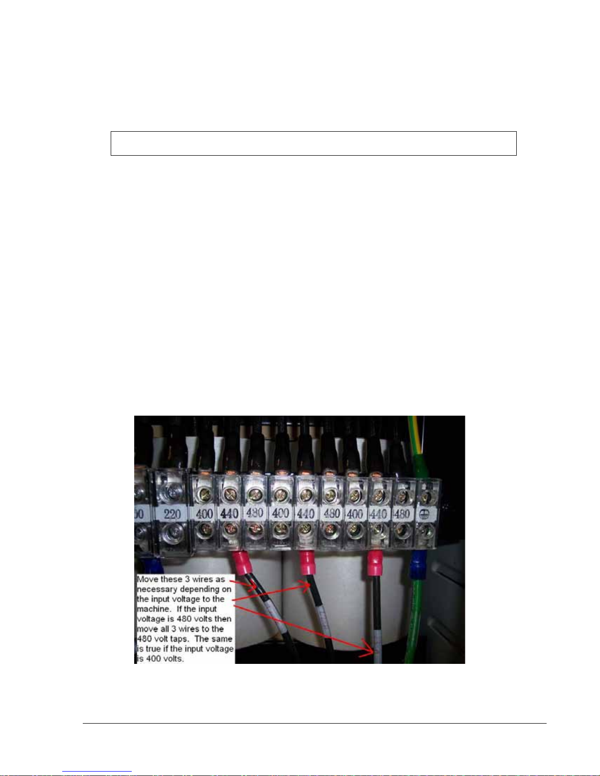
2.4.16 Transformer Option
The TRAK LPM comes with an optional step down transformer, which takes 440 volts down to
220 volts. The transformer comes with multiple taps to allow for up to 3 different input voltages.
The 3 taps are rated for 400, 440 and 480 volts. See figure 2.4.16a. The machine ships out
from the factory with the wires attached to the 440-volt taps. Please adjust these 3 wires
depending on the input voltage to the machine.
There is also a 200 volt and 220 volt tap on the secondary side of the transformer. In most
cases the wires will be on the 220-volt tap. As a general rule, we would like the output voltage
from the transformer to be between 220 and 230 volts. On a rare occasion where the customers
shop is around 500 volts, it may be necessary to move the wires from the 220 to 200 volt tap.
You should also place the primary side wires on the 480 taps.
In the case of 415 volts, it is better to place the wires on the 400-volt taps as the output voltage
will be closer to 230 volts.
Figure 2.4.16a
Please see drawing 26939 at the rear of the manual for more information.
WARNING!
Use Extreme Care When Working with the Auger, serious injury could occur.
Other manuals for TRAK LPM
1
Table of contents
Other Southwestern Industries Sander manuals


