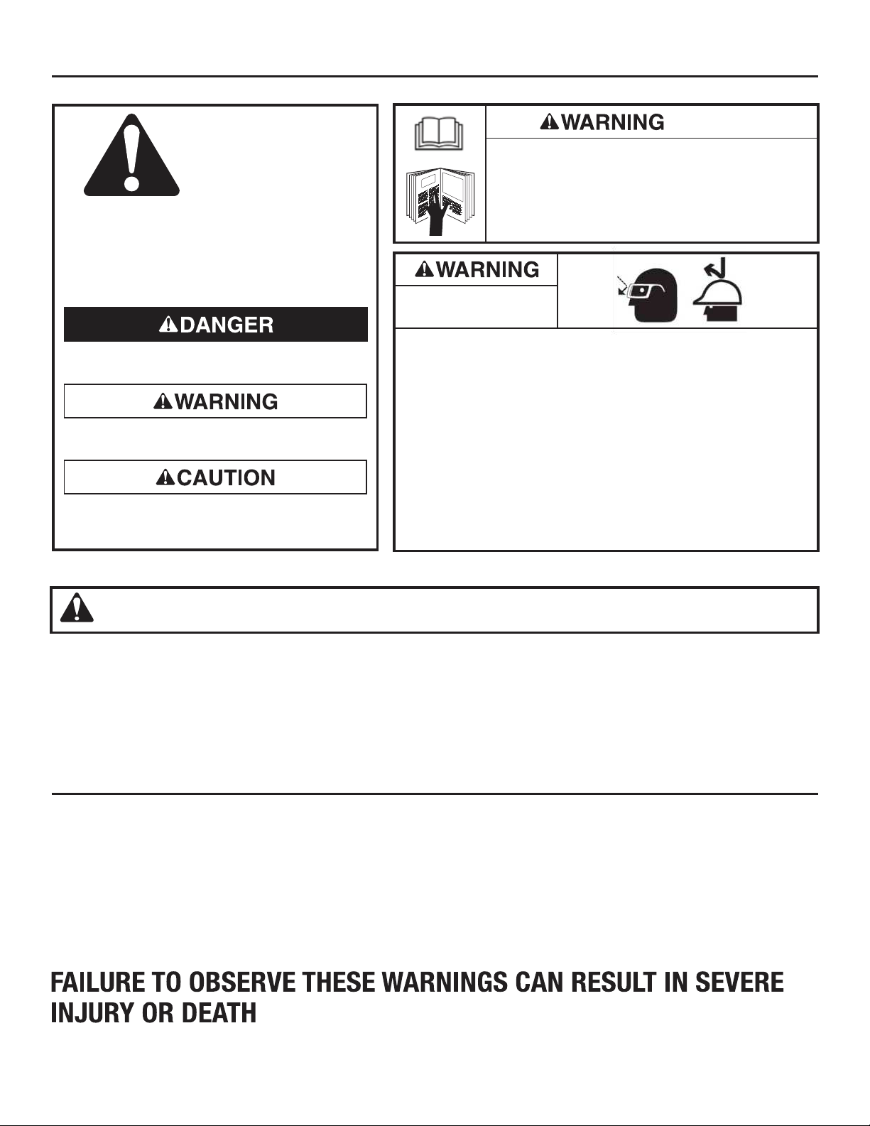
SAFETY ALERT SYMBOLS
These symbols are used to call attention to related
hazards or unsafe practices related that could result
in injury or property damage. The three safety words
defined below indicate the severity of the hazard.
The message after the signal word provides
information for preventing or avoiding the hazard.
Hazards or unsafe practices which, if not avoided,
MAY result in injury or property damage.
Hazards which, if not avoided, COULD result in
severe injury or death.
Immediate hazards which, if not avoided, WILL
result in severe injury or death.
SAFETY
ALERT
SYMBOLS
Personal
safety hazards
Read and understand all of the instructions and
safety information in this manual before operating
or servicing this tool.
• Only qualified persons should use SIMpull™ Cable Guide System
• Wear eye protection when using this tool.
• Do not use tool while tired or under the influence of drugs, alcohol,
or medication.
• Keep body parts and loose clothing away from moving parts.
• Always wear gloves when handling SIMpull™ Cable Guide
System parts.
• Keep all body parts clear of cable path while the SIMpull™ Cable
Guide System is in use.
• When using this tool, always follow the safety procedures
set forth in this manual as well as all other safety procedures
necessary and proper when using tools of this type.
Failure to observe this warning could result in
severe injury or death.
WARNING
:Personal Safety Hazards.
• Use this tool for manufacturer’s intended purpose only. Any use other than
described in this manual can result in injury or property damage.
• Only qualified persons should use the SIMpull™ Cable Guide System.
This instruction manual is intended to familiarize personnel with the safe
operation and maintenance procedures for the SIMpull™ Cable Guide
System. Keep this manual available to all personnel.
Replacement manuals are available upon request at no charge
at www.southwiretools.com
PURPOSE OF THIS MANUAL
2