Sovereign Simplicity 572-3212H User manual

5»/mii//cily
SOVEREIGN
RIDING
TRACTORS
HYDROSTATIC
DRIVE
m
I
1
f
iiiiii
1
,
1970
PRODUCTION
YEAR
Mfrs.
No.
572-3212H
MANUAL
LIFT
Mfrs.
No.
573-3212H
POWER
LIFT
SIMPLICITY
MANUFACTURING
COMPANY
UTHO
W
U.lA
Should
warranty
service
lie
necessary,
the
Information
below
should
be
presented
to
the
author¬
ised
SIMPLICITY
Dealer.
Customers
Name_
Address
_
Mtfj.
No._Serial
No._
DilLu
J
*urt:hnsui
I_
I’urL'hj^l
KfOm_
Address_
_
_____
.
^nj^ini'
Model
No._Serial
No.
_
_
_
_
T
ype
No._
To
oirtain
nupiucemiml
parts
from
dealer,
advise
quantity,
part
number
and
description.
Re
*
e
m
b
*'
i
i
FOR
YOUR
SAFETY
]
ALWAYS
STOP
ENGINE
BEFORE
LEAVING
MACHINE
2
ALWAYS
STOP
ENGINE
BEFORE
SERVICING
OR
ADJUSTING
MACHINE
OR
EQUIPMENT
y
ALWAYS
KEEP
HANDS,
FEET
AND
CLOTHING
AWAY
FROM
POWER-DRIVEN
PARTS
i
i
LJ

PACKING
This
tractor
is
delivered
complete
in
one
car-
ion.
Thecarlori
contains:
1
-
Tractor
Assembly
1
-
Steering
Wheel
(in
skin
pack)
1
-
Hardware
Pack
Should
any
shortages
of
the
above
items
oc-
cur,
advise
by
stating
packers
number
listed
on
green
packing
slip,
serial
number
of
tractor,
part
number
and
description
of
items
missing.
ASSEMBLY
BATTERY
Remove
battery
from
tractor.
Service
as
stated
in
the
battery
instructions.
Replace
and
secure
battery
in
tractor.
STEERING
WHEEL
Assemble
steering
wheel
on
the
steering
shaft
using
the
woodruff
key
and
setscrew
which
is
pro¬
vided
in
the
hardware
pack.
Assemble
steering
cap
over
hub
of
steering
wheel.
SHORT
TIME.
A
funnel
and
extension
are
included
with
the
tractor
for
use
in
changing
oil.
The
bevel
gear
housing
has
a
capacity
of
one
pint
of
5AE
90
oil
and
is
filled
at
the
factory.
It
will
not
normally
require
replenishment,
but
occa¬
sionally
check
drain
plug
for
tightness
and
oil
seals
for
leakage.
Keep
oil
up
to
level
of
filler
plug-
See
Figure
8.
TRACTOR
LUBRICATION
The
tractor
has
a
total
of
3
grease
fittings
which
require
Lubrication
with
general
purpose
au¬
tomotive
grease.
Use
a
standard
grease
gun
for
the
following
fittings:
(2)
Front
Spindles
(1)
Rear
Axle
Tube
Before
lubricating,
wipe
each
grease
fitting
with
a
rag
to
prevent
grit
and
dirt
from
being
car¬
ried
into
bearings
with
new
grease.
ENGINE
LUBRICATION
Service
air
cleaner
and
crankcase
as
recom¬
mended
in
FngincService
Manual.
Be
sure
air
clean¬
er
is
maintained
in
dean
condition.
Never
use
oil
in
crankcase
for
more
than
25
hours
of
operation.
See
Figure
It.
CLEAN
AIR
AND
CLEAN
ENGINE
OIL
WILL
GIVE
LONG
TROUBLE
FREE
OPER¬
ATION.
DIRT
WILL
RUIN
VOUR
ENGINE
IN
A
The
transmission
hasa
capacity
of
1-1/2
qts.
of
SAE90
oil
and
is
filled
at
the
factory.
It
will
not
normally
require
replenishment,
but
occasionally
cheek
drain
plug
for
tightness
and
axle
tube
oil
seals
for
leakage.
Maintain
oil
level
at
lower
edge
of
fill¬
er
plug
hole.
Remove
vent
plug
from
top
of
trans¬
mission
and
allow
oil
to
settle
to
normal
Level
be¬
fore
checking.
See
Figure
7.
GREASE
FITTING
ROLLER
BEARING
ft...
In
hctaiY
irtnd.
At
list
vtiilv,
dtan
and
rapack
with
buring
petit,
GREASE
FITTING
l\
LUBRICATION
POINTS
FIGURES
1
TO
G
DELETED
Figure
7
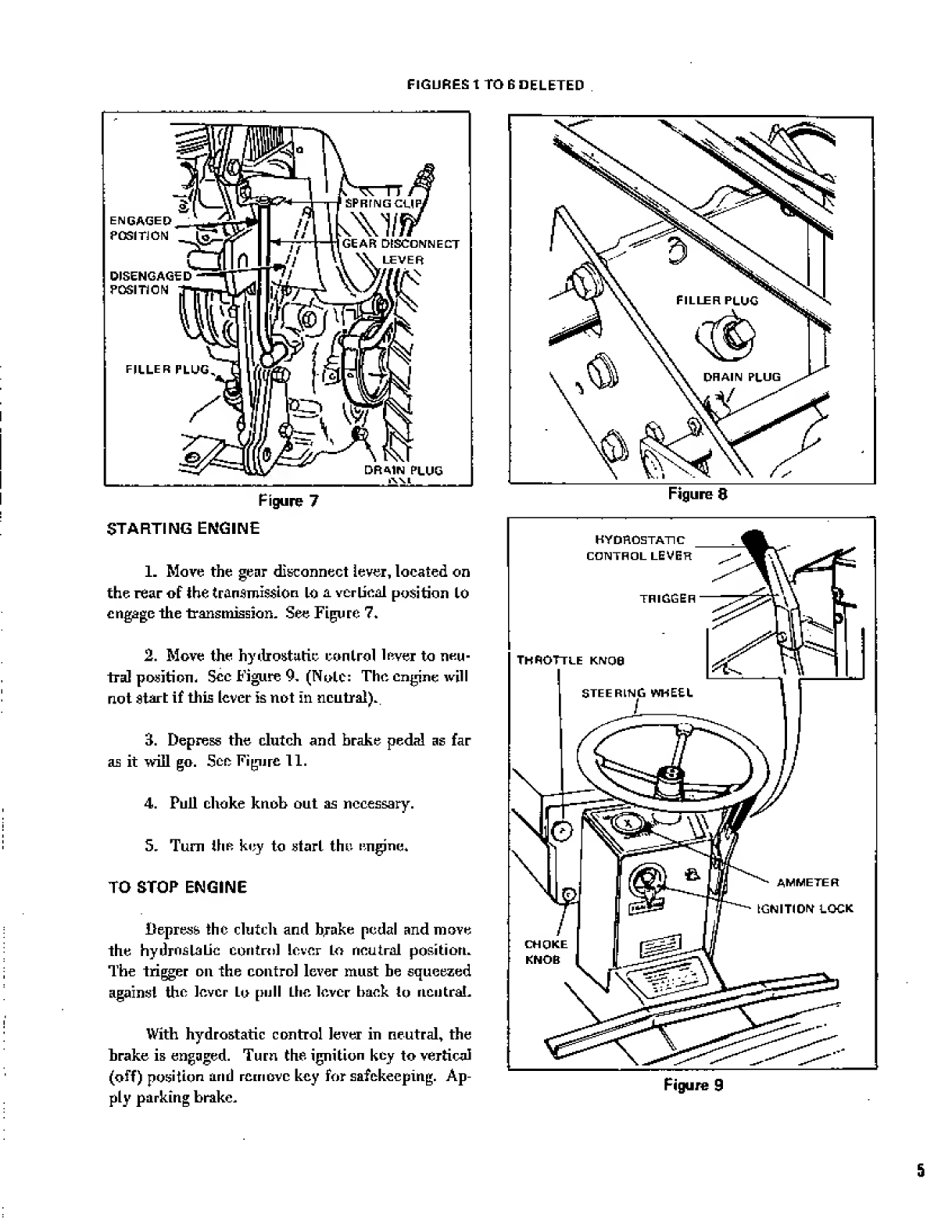
STARTING
ENGINE
1.
Move
the
gear
disconnect
lever,
located
on
the
rear
of
the
transmission
Lo
a
vertical
position
to
engage
the
transmission-
See
Figure
7*
2.
Move
the
hydrostatic
control
lever
to
neu¬
tral
position-
Sec
Figure
9.
(Note:
The
engine
will
not
start
if
this
lever
is
not
in
neutral).
3.
Depress
the
clutch
and
brake
pedal
as
far
as
it
will
go.
See
Figure
11.
4.
Pull
choke
knob
out
as
necessary.
5.
Turn
the
key
to
start
the
engine*
TO
STOP
ENGINE
Depress?
the
dutch
and
b,rake
pedal
and
move
the
hydrostatic
con
in
>1
lever
Lo
neutral
position.
The
trigger
on
the
control
lever
must
be
squeezed
against
the
lever
to
pull
the
lever
back
to
neutral.
With
hydrostatic
control
lever
in
neutral,
the
brake
is
engaged.
Turn
the
ignition
key
to
vertical
(off)
position
and
remove
key
for
safekeeping.
Ap¬
ply
parking
brake.
Figure
8
Figure
9
5
BRACKET
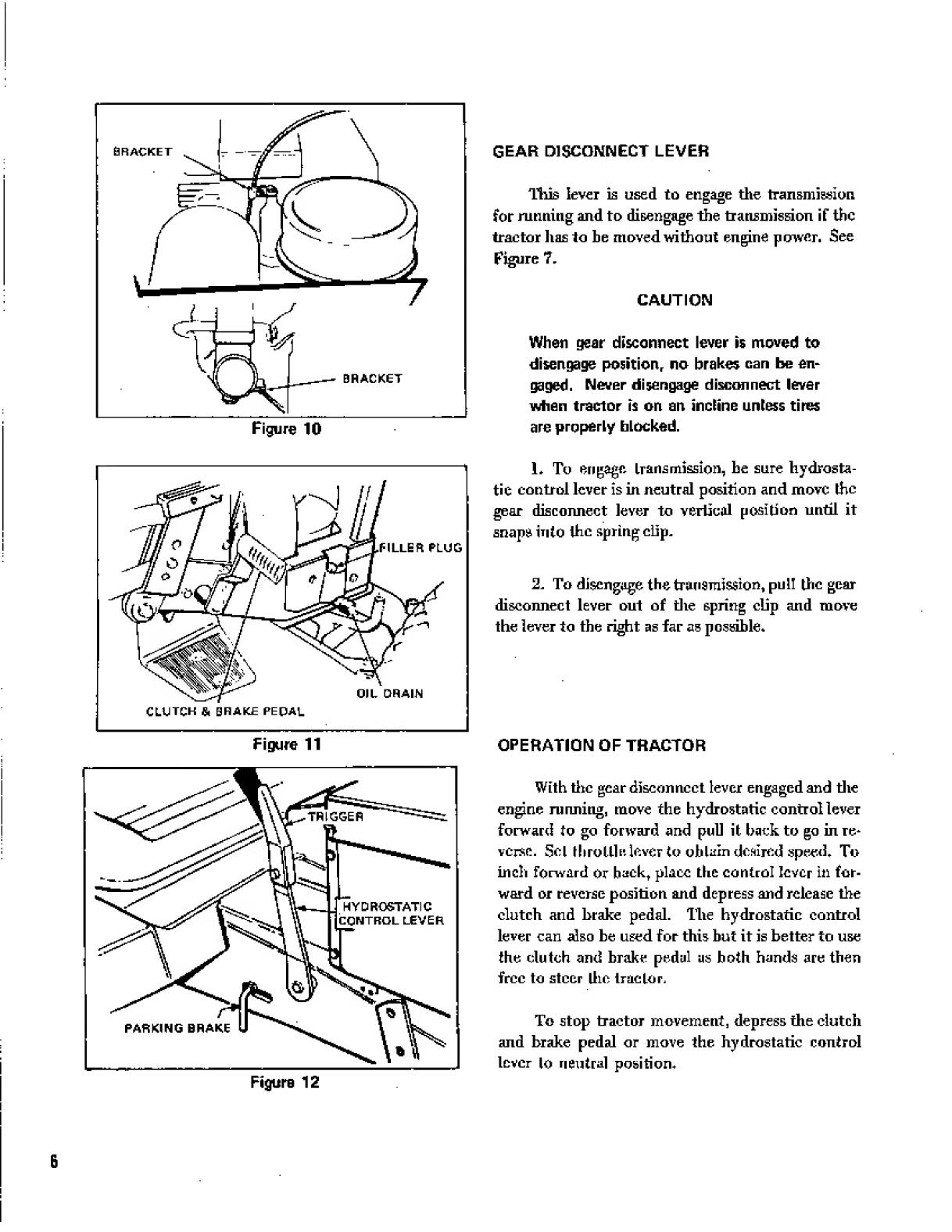
GEAR
DISCONNECT
LEVER
lliis
lever
is
used
to
engage
the
transmission
for
running
and
to
disengage
the
transmission
if
the
tractor
lias
to
be
moved
without
engine
power.
See
Figure
7,
CAUTION
When
gear
disconnect
lever
is
moved
to
disengage
position,
no
brakes
can
be
en¬
gaged.
Never
disengage
disconnect
lever
when
tractor
is
on
an
incline
unless
tires
are
properly
blocked.
L
To
engage
transmission,
he
sure
hydrosta¬
tic
control
lever
is
in
neutral
position
and
move
the
gear
disconnect
lever
to
vertical
position
until
it
snaps
into
the
spring
clip.
2.
To
disengage
the
transmission,
pull
the
gear
disconnect
lever
out
of
the
spring
clip
and
move
the
lever
to
the
right
as
far
as
possible.
Figure
11
Figure
12
OPERATION
OF
TRACTOR
With
the
gear
disconnect
lever
engaged
and
the
engine
running,
move
the
hydrostatic
control
lever
forward
to
go
forward
and
pull
it
back
to
go
in
re¬
verse.
Sol
throttle
lover
to
oh
lain
desired
speed.
To
inch
forward
or
back,
place
the
control
lever
in
for¬
ward
or
reverse
position
and
depress
and
release
the
clutch
and
brake
pedal.
The
hydrostatic
control
lever
can
also
he
used
for
this
but
it
is
better
to
use
the
dutch
and
brake
pedal
as
both
hands
are
then
free
to
steer
ihc
tractor.
To
stop
tractor
movement,
depress
the
clutch
and
brake
pedal
or
move
the
hydrostatic
control
lever
lo
neutral
position.
6

CLUTCH
ADJUSTMENT
If
the
tractor
creeps
forward
or
back
when
the
hydrostatic
control
Lever
is
in
neutral,
the
turn-
buckle
on
the
control
linkage
should
he
adjusted.
See
Figure
13.
Loosen
the
locknuts
at
each
of
the
turnbtmklcs
and
rotate
the
tumbucfcle
clockwise
or
counter¬
clockwise
as
necessary
until
the
tractor
does
not
creep.
Re
tighten
the
locknuts
using
Lwo
wrenches
so
turn
buckle
will
110
L
Lie
moved
and
observe.
tractor
to
he
sure
it
does
not
creep.
Readjust
if
necessary.
BRAKE
ADJUSTMENT
The
brake
sLiouLd
he
adjusted
to
provide
full
braking
when
the
clutch
brake
pedal
is
completely
depressed.
Place
the
hydrostatic
control
lever
in
neutral
position.
Repress
clutch
L>rake
pedal
completely
and
turn
the
brake
band
adjusting
nut
until
the
brake
band
is
tight
against
the
brake
drum.
See
Fig¬
ure
13.
HYDRAULIC
SYSTEM
MAINTENANCE
To
be
sun
1
of
satisfactory
performance
it
is
important
thal
flic
hydraulic
oil
is
kept
absolutely
dean
and
that
the
level
of
oil
in
the
oil
reservoir
be
maintained.
See
Figure
13,
Before
checking
the
hydraulic
oil
level,
be
sure
the
outside
of
the
hydraulic
oil
reservoir
is
clean
end
no
debris
will
enter
the
reservoir.
(llicck
hydraulic
oil
level
hy
removing
Mir
in¬
spection
plug
on
thr
side
and
near
the
tup
of
the
reservoir.
If
oil
runs
out
of
Mu-
bole,
the
reservoir
is
full
and
the
plug
should
be
replaced.
IF
oil
does
not
rim
out
of
the
hole,
replace
the
in
spec
I
ion
plug,
remove
the
nut
and
cover
from
lop
of
the
reservoir
and
add
oil
to
the
reservoir
until
it
reaches
I
he
level
BRAKE
BAND
ADJUSTING
NUT
Figure
13
of
the
inspection
plug,
Use
only
Uexron
A.T,F.
{Automatic
Transmission
Fluid)
which
is
available
locally
from
several
major
oil
companies.
Capacity
of
Mir
System
is
1-3/4
quarts,
A
Tier
every
five
(5)
hours
of
operation
(more
often
in
dusty
conditions)
remove
the
snap-oul
plug
from
the
fan
and
oil
cooler
housing
and
clean
fan
and
housing
with
air
or
wafrr
under
pressure.
Replace
the
plug
hy
pressing
it
unto
the
hole.
The
hydraulic
uEl
filler
in
the
bottom
of
the
reservoir
has
lo
lie
changed
only
when
dirt
gets
info
the
hydraulic
oil
in
the
reservoir.
To
change
flic
filter,
remove
the
nut
and
cover
from
lop
of
reser¬
voir,
Have
a
container
ready
to
catch
the
oil
and
disconnect
one
of
the
hoses
at
the
hoi
lorn
of
the
oil
reservoir,
Raise
the
end
of
the
hose
and
tie
it
up
so
oil
will
not
run
out
of
the
transmission.
Drain
the
oil
from
the
reservoir
into
the
container.
Remove
the
111
ter
and
replace
with
a
new
one-
Add
Dexron
Automatic
Transmission
Fluid
to
the
reservoir
up
Lo
the
level
of
the
inspection
plug.
Re¬
place
the
cover
and
nut
on
the
reservoir.
7

DIFFERENTIAL
The
tractor'is
equipped
with
a
controlled
trac¬
tion
differential.
Tightening
the
hex
head
capserews
in
the
right
hand
wheel
huh
(See
Figure
14.),
pro¬
vides
pressure
against
a
nylon
plug
and
sleeve
around
the
tractor
axle
and
prevents
excessive
wheel
slip¬
page
when
the
tractor
is
being
used
under
abnormal
conditions
The
adjusting
capscrews
are
set
at
the
factory
to
a
torque
of
25
ft.
lbs-
As
the
nylon
sets
itself
tlirough
use,
it
may
he
necessary
to
readjust
the
capscrews
a
few
times
to
maintain
25
ft.
lbs.
of
torque
(25
lbs.
weight
on
wrench
1
ft,
long).
ADJUSTING
CAPSCREWS
RIGHT
HAND
WHEEL
HU&Sr
CAUTION
DO
NOT
APPLV
MORE
THAN
30
FT.
LBS*
TO
THE
ADJUSTING
CAPSCREWS1
Figure
14
POWER
TAKE-OFF
LUBRICATION
TTie
power
take-off
is
lubricated
by
means
of
one
grease
fitting
located
on
the
bottom
front
of
the
drive
bracket
assembly*
Occasionally
apply
grease
by
means
of
a
standard
grease
gun
loaded
with
automotive
type
grease.
Be
sure
to
wipe
dirt
and
grit
from
grease
fitting
before
applying
grease
gun.
Lubricate
all
pivot
points
and
idler
pulley
bearings
with
SAE
20
oil
every
few
hours
of
opera¬
tion.
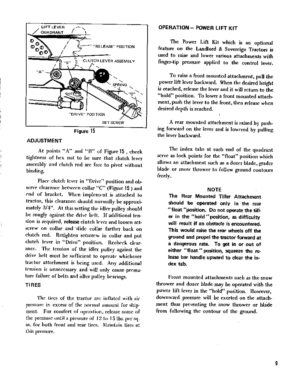
OPERATION
Operation
of
the
power
take-off
is
controlled
by
movement
of
the
dutch
lever
assembly.
See
Fig¬
ure
15.
When
the
dutch
lever
is
in
the
forward
raised
position,
the
clutch
rod
releases
the
tension
holding
the
idler
pulley
against
the
drive
bell
and
power
will
not
be
transmitted
to
the
driven
pulley
of
the
power
take-off
assembly.
When
the
dutch
lever
is
in
the
back,
depressed
position,
lhe
clutch
rod
applies
tension
to
the
idler
pulley
and
as
the
id¬
ler
pulley
takes
up
the
stack
in
the
drive
belt,
power
is
transmitted
from
the
drive
pulley
on
bevel
gear
box
shaft
to
the
driven
pulley
of
the
power
take¬
off-
Figure
15
shows
clutch
lever
in
drive
position*
|___
SET
SCREW
Figure
15
ADJUSTMENT
At
points
“A”
and
“li”
of
Figure
15
,
check
tightness
of
hex
nut
to
be
sure
that
clutch
lever
assembly
and
clulch
rod
are
free
to
pivot
without
binding.
Place
clutch
lever
in
“Drive
1
*
position
and
ob¬
serve
clearance
between
collar
“C”
(Figure
15
)
and
end
of
bracket.
When
implement
is
attached
lo
tractor,
this
clearance
should
normally
be
approxi¬
mately
3/4”.
At
this
setting
the
idler
pulley
should
be
snugly
against
the
drive
belt.
If
additional
tern
sion
is
required,
release
clutch
lever
and
loosen
set¬
screw
on
collar
and
slide
collar
farther
back
on
dutch
rod.
Ftetighien
setscrew
in
collar
and
put
clutch
lever
in
“Drive”
position.
Rccbeek
clear¬
ance.
The
tension
of
the
idler
pulley
against
ihe
drive
belt
must
be
sufficient
to
operate
whichever
tractor
attachment
is
being
used.
Any
additional
tension
is
unnecessary
and
will
only
cause
prema¬
ture
failure
oT
belts
and
idler
pulley
bearings.
TIRES
The
tires
of
the
tractor
are
inflated
with
air
pressure
in
excess
of
the
normal
amount
for
ship¬
ment,
For
comfort
of
opera
I
ion,
release
some
of
the
pressure
until
a
pressure
of
1
2
In
15
lbs,
per
sq.
in.
for
both
front
and
rear
tires.
Maintain
lires
at
this
pressure.
OPERATION-
POWER
LIFT
KIT
r
Hic
Power
Lift
Kit
which
is
an
optional
feature
on
the
Landlord
&
Sovereign
Tractors
is
used
to
raise
and
lower
various
attachments
with
finger-tip
pressure
applied
to
tlic
control
lever.
To
raise
a
front
mounted
attachment,
pull
the
power
lift
lever
backward.
When
the
desired
height
is
reached,
release
the
lever
and
it
will
return
to
the
“hold"
position.
To
lower
a
front
mounted
attach¬
ment,
push
tire
lever
to
the
front,
then
release
when
desired
depth
is
reached.
I
A
rear
mounted
attachment
is
raised
by
push¬
ing
forward
on
the
lever
and
is
lowered
by
pulling
the
lever
backward.
The
index
tabs
at
each
end
of
the
quadrant
serve
as
lock
points
for
the
“float”
position
which
allows
an
attachment
such
as
a
dozer
blade,
grader
blade
or
snow
thrower
to
follow
ground
contours
freely,
NOTE
The
Rear
Mounted
Tiller
Attachment
should
be
operated
only
in
the
rear
"float
"position.
Do
not
operate
the
till¬
er
in
the
"hold
"position,
as
difficulty
will
result
if
an
obstacle
is
encountered.
This
would
raise
the
rear
wheels
off
the
ground
and
propel
the
tractor
forward
at
a
dangerous
rate.
To
get
in
or
out
of
either
"float
"
position,
squeeze
the
re¬
lease
bar
handle
upward
to
clear
the
in¬
dex
tab.
E'ront
mounted
attachments
such
as
the
snow
thrower
and
dozer
blade
may
be
operated
with
the
power
lift
lever
in
the
“hold”
position.
However,
downward
pressure
will
he
exerted
on
tire
attach¬
ment
thus
preventing
the
snow
thrower
or
blade
from
following
the
contour
of
the
ground.
9
O
yn,-
-
i
“K
SO
l
«^7
/
/
/
/
L
_
/
"7,
A*
r
t
//
wA-a
4
/
/
/
$L
_
s"
/
/
/
^Aj;
a
/
/
/
j8\
/
v
/,
7"
5
/
r
<hj
s
/
<44
^
/
°
-
\
\
V
l
j
)
^
'
i-u,
■
\
\
y
i
/
*3
\
Tx
\
/
5^'.
;
\
S£wT
A-^
/
-"XMh/
,
/
_^v
\K$'
;
I
.'Mf
X'
u
or
<6
/
(
£
j
C
A
visrsx
4
uiOVfi
ThIZ
o
J
J
14
^
JO,
£^
u
i
“Q*J"
*
u
HI
Hi
<J
u
>
-5**
«
1U
■
?
i-
-1
O
Otu>-
™
LU
■
*.
,^oo
U
T
^
IT
III
4
^
^
s
G_
K
BC
si-
t
i_
1
ij
ji
w
.
rs
b
ii
h
>
-T^
h
t-ILLL^h
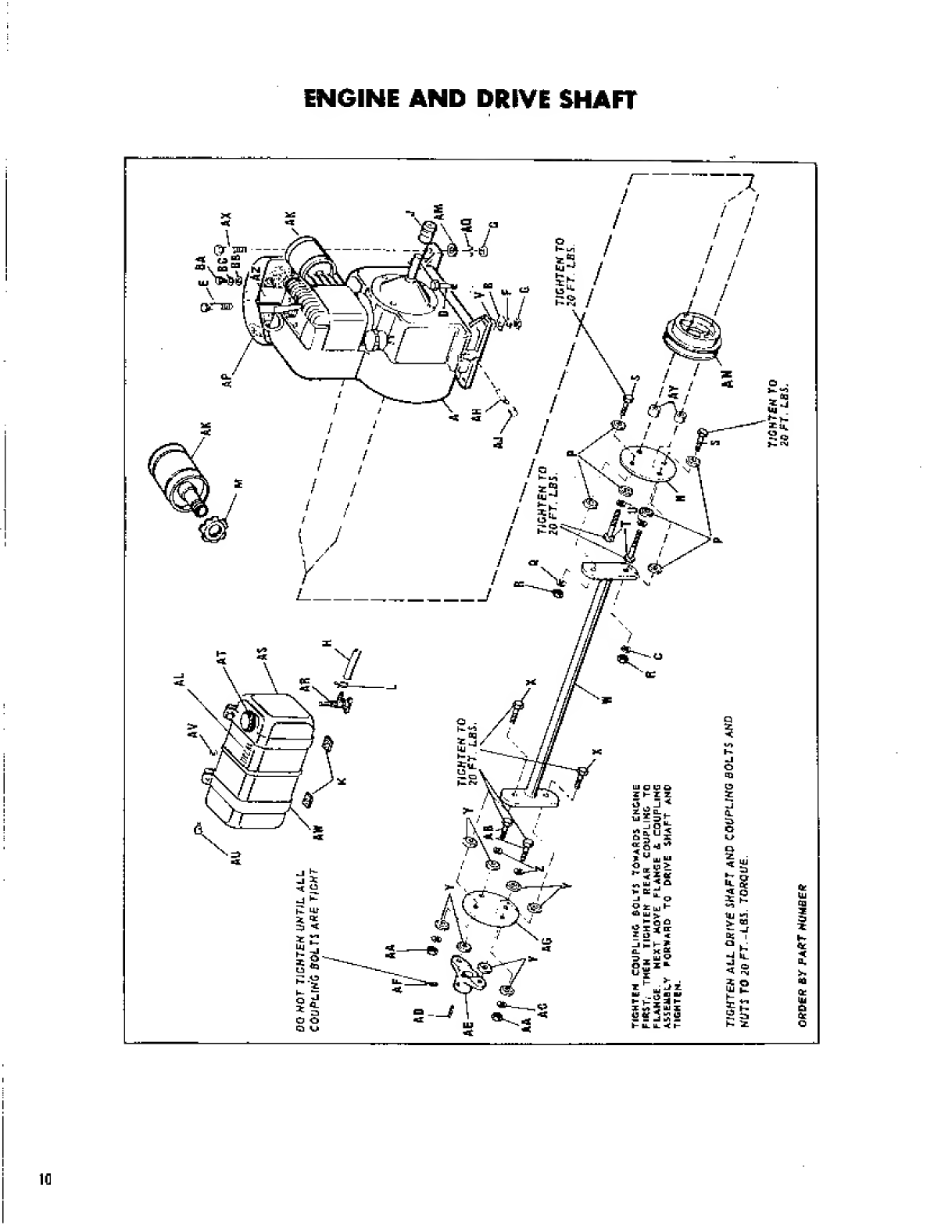
ORDER
fir
PART
DUMBER
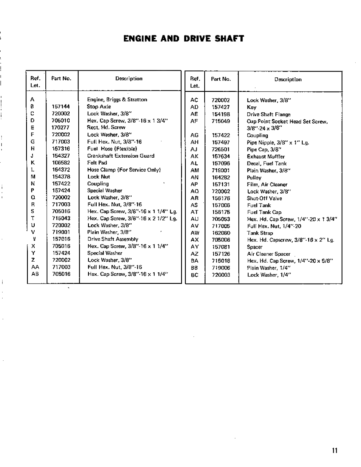
ENGINE
AND
DRIVE
SHAFT
Ref.
Let.
Part
No.
Description
A
Engine,
Briggs
&
Stratton
B
157144
Stop
Axie
C
720002
Lock
Washer,
3/8"
D
705010
Hex.
CapScrew,
3/8"-16x
1
3/4"
E
170277
Rect.
Hd,
Screw
F
720002
Lock
Washer,
3/8"
G
717003
Full
Hex.
Nut,
3/8^16
H
157316
Fuel
Hose
(Flexible)
J
154327
Crankshaft
Extension
Guard
K
106582
Felt
Pad
L
154372
Hose
Clamp
(For
Service
Only)
M
154378
Lock
Nut
N
157422
Coupling
P
157424
Special
Washer
G
720002
Lock
Washer,
3/B"
R
717003
Full
Hex.
Nut,
3/8"-16
S
705016
Hex.
Cap
Screw,
3/8'M6
x
1
1/4"
Lg.
T
715043
Hex.
Cap
Screw,
3/8"-16
x
2
1/2"
Lg.
U
720002
Lock
Washer,
3/8"
V
719001
Plain
Washer,
3/8"
V
157016
Drive
Shaft
Assembly
X
705016
Hex.
Cap
Screw,
3/8"-TG
x
1
1/4"
Y
157424
Special
Washer
z
720002
Lock
Washer,
3/S"
AA
717003
Full
Hex.
Nut,
3/8"-16
AB
705016
Hex.
Cap
Screw,
3/8"-16
x
1
1/4"
Ref.
Let.
Part
No.
Description
AC
720002
Lock
Washer,
3/8"
AD
157427
Key
AE
154198
Drive
Shaft
Flange
AF
715049
Cup
Point
Socket
Head
Set
Screw,
3/8"-24
x
3/8"
AG
157422
Coupling
AH
157497
Pipe
Nipple,
3/B"
x
1"
Lg,
AJ
726501
Pipe
Cap,
3/8"
AK
167634
Exhaust
Muffier
AL
157096
Decal,
Fuel
Tank
AM
710001
Plain
Washer.
3/8"
AN
1642B2
Pulley
AP
157131
Film,
Air
Cleaner
AG
720002
Lock
Washer,
3/B"
AR
156176
Shut-Off
Valve
AS
157006
Fuel
Tank
AT
156175
Fuel
Tank
Cap
AU
705053
Hex,
Hd.
Cap
Screw,
1/4"-20
x
1
3/4"
AV
717005
Fuli
Hex.
Nut,
1/4"-20
AW
162060
Tank
Strap
AX
705006
Hex.
Hd.
Capscrew,
3/8"-16
x
2"
Lg.
AY
157081
Spacer
AZ
157126
Air
Cleaner
Spacer
BA
715018
Hex.
Hd.
Cap
Screw,
1/4"-20
x
5/8"
88
719006
Plain
Washer,
1/4"
BC
720003
Lock
Washer,
1/4"
11

FRAME
iTali
,
GRILL,
&
INST.
PANEL
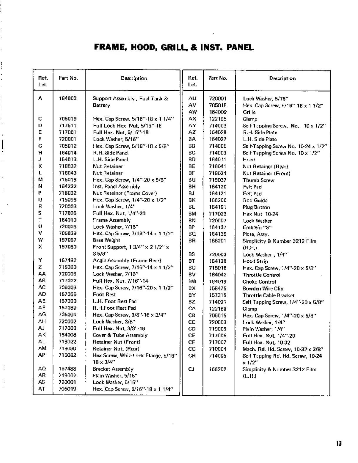
FRAME,
HOOD,
GRILL,
&
INST.
PANEL
Ref.
Let.
Part
No.
Description
Ref.
Let.
Part
No.
Description
A
1G4003
Support
Assembly
,
Fuel
Tank
fit
AU
720001
Lock
Washer,
5/15"
Battery
AV
705018
Hex.
Cap
Screw,
5/15"-18
x
1
1/2"
AW
164009
Grille
C
705019
Hex.
Cap
Screw.
5/1G"-1fi
x
1
1/4'
r
AX
122195
Clamp
D
717511
Full
Lock
Hex.
Nut,
5/1G"-16
AY
714003
SelfTappingScrew,
No,
10x1/2"
E
717001
Full
Hex.
Nut,
5/16"
18
AZ
164028
R,H.
Side
Plate
F
720001
Lock
Washer,
5/16"
BA
164027
L.H.
Side
Prato
G
705012
Hex.
Cap
Screw,
5/16
Hr
-16
x
5/8"
3B
714005
Self-Tapping
Screw
No.
10-24
x
1/2”
H
164014
R,H,
Side
Panel
BC
714003
Self
Tapping
Screw
No,
10
x
1/2”
J
164013
L.H.
Side
Panel
BD
164011
Hood
K
71E032
Nut
Retainer
BE
71E041
Nut
Retainer
(Rear)
L
71E043
Nut
Retainer
BF
716024
Nut
Retainer
(Front)
M
715013
Hex.
CapScrew,
1/4"-20x
5/3"
BG
715037
Thumb
Screw
N
1G4232
Inst,
Panel
Assembly
BH
164120
Felt
Pad
P
718032
Nut
Retainer
(Frame
Cover)
BJ
164121
Felt
Pad
Q
715098
Hex.
CapScrew,
l/4"-2G
X
1/2"
BK
166200
Rod
Guide
R
720003
Lock
Washer,
1/4"
BL
164191
Plug
Button
S
717005
Full
Hex,
Nut,
1/4"
20
BM
717023
Hex
Nut
10-24
T
164010
Frame
Assembly
BN
720007
Lock
Washer
u
720005
Lock
Washer,
7/16"
BP
164137
Emblem
,J
S”
V
705039
Hex.
Cap
Screw,
7/16"-14xl
1/2”
BQ
164135
Plate,
Assy,
w
157057
Base
Weight
BR
166201
Simplicity
&
Number
3212
Film
X
157050
Front
Support,
1
3/4"
x
2
1/2”
x
(R.H.)
8
5/8"
BS
720003
Lock
Washer
,
1/4"
Y
157432
Angie
Assembly
(Frame
Rear)
BT
164129
Hood
Strip
z
715030
Hex,
Cap
Screw,
7/16"-14
x
1
1/2"
BU
715016
Hex,
Cap
Screw,
1/4"-20
x
S/S"
AA
720005
Lock
Wesher,
7/16"
BV
164042
Throttle
Control
AB
717022
Full
Hex.
Nut,
7/16"-14
BW
154019
Choke
Control
AC
705003
Hex,
Cap
Screw,
7/l6"-20
x
1
1/2"
BX
153475
Bowden
Wire
Clip
AD
157055
Foot
Rest
BY
157315
Throttle
Cable
Bracket
AE
157000
L.H.
Foot
Rest
Pad
BZ
714021
Self
Tapping
Screw,
1/4"-2D
x
5/3"
AF
157030
R.H.Foot
Rest
Pad
CA
122186
Clamp
AG
705004
Hex.
Cap
Screw,
3/fi"-16
x
3/4"
CB
705015
Hex,
Cap
Screw,
1
/4"'2C
x
5/3”
AH
720002
Lock
Washer,
3/8
rH
CC
720003
Lock
Washer,
1/4"
AJ
717003
Full
Hex.
Nut,
3/8"16
CD
719005
Plain
Washer,
1/4”
AK
154003
Cover
&
Tube
Assembly
CE
717005
Full
Hex.
Nut,
1/4”-20
AL
713022
Retainer
Nut
(Front)
CF
717007
Full
Hex.
Nut,
10
32
AM
713030
Retainer
Nut,
(Rear)
CG
710004
Mach,
Rd.Hd.
Screw,
10-32
x
3/8"
AP
715062
Hex
Screw,
Whiz'Lock
Flange,
5/16"-
CH
714005
Self
Tapping
Rd.
Hd.
Screw,
10-24
18
x
3/4"
x
1/2”
AQ
157466
Bracket
Assembly
CJ
166202
Simplicity
St
Number3212
Film
AR
719002
Plain
Washer,
5/16"
(L.H.)
AS
720001
Lock
Washer,
5/16"
AT
705019
Hex.
CapScrew,
5/16
F
'-1Bx
1
1/4
Jd
L—^_,_
1
13
i
!
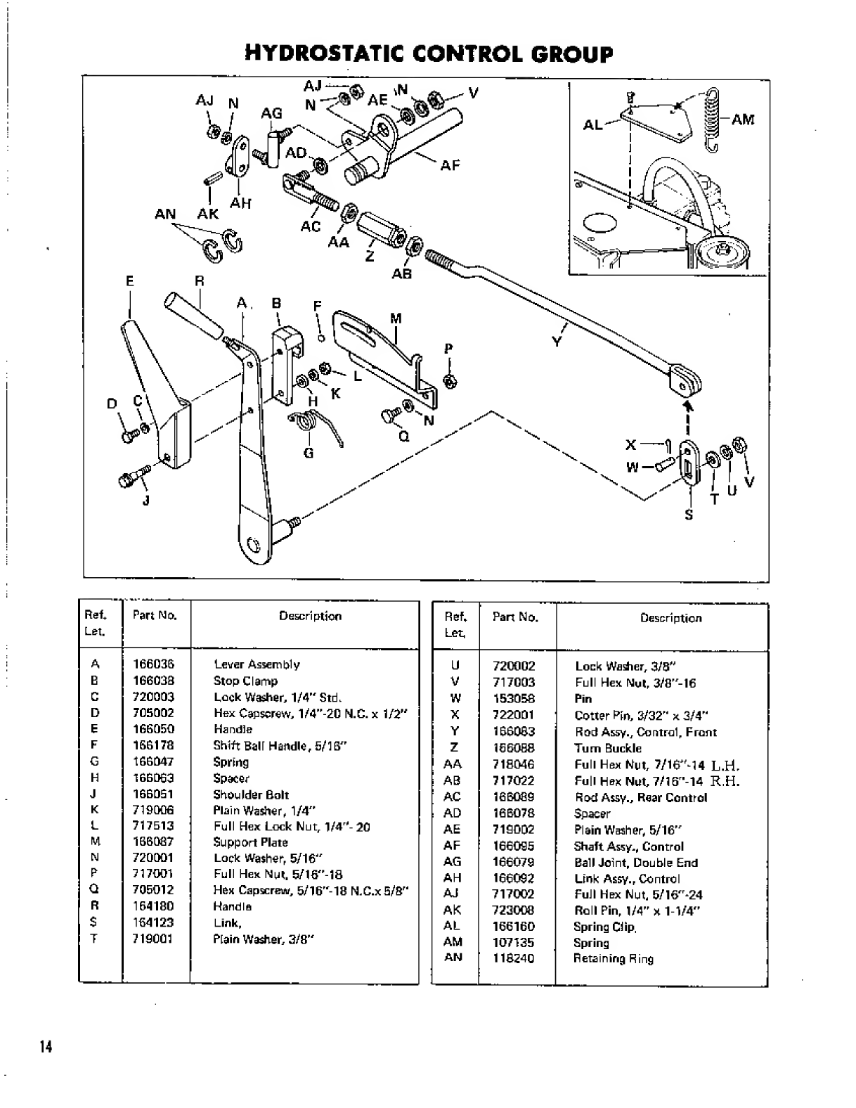
HYDROSTATIC
CONTROL
GROUP
Ref*
Let.
Part
No.
Description
A
166036
Lever
Assembly
E
1G6033
Stop
Clamp
C
720003
Lock
Washer,
1/4"
Std.
D
706002
Hex
Capscrew,
1/4”-20
N.C.
x
1/2"
E
166050
Handle
F
166178
Shift
Ball
Handle,
5/16"
G
166047
Spring
H
166063
Spacer
J
166061
Shoulder
Bolt
K
719006
Plain
Washer,
1/4"
L
717513
Full
Hex
Lock
Nut,
1/4
rH
-
20
M
166087
Support
Plate
N
720001
Lock
Washer,
5/16"
P
717001
Full
Hex
Nut,
5/16"-1B
G
705012
Hex
Capscrew,
5/16"-18
N.C.xS/S"
R
164180
Handle
$
164123
Link,
T
719001
Plain
Washer,
3/8"
Ref*
Part
No.
Description
Let,
U
720002
Lock
Warier,
3/8"
V
717003
Full
Hex
Nut,
3^8"-16
W
153068
Pin
X
722001
Cotter
Fin,
3/32"
x
3/4"
Y
166033
Rod
Assy.,
Control,
Front
z
IS
6088
Turn
Buckle
AA
718046
Full
Hex
Nut,
7/16"
14
L.H.
AB
717022
Full
Hex
Nut,
7/16"-14
R.H.
AC
166089
Rod
Assy.,
Rear
Control
AD
166078
Spacer
AE
719002
Plain
Washer,
5/16"
AF
166095
Shaft
Assy,,
Control
AG
166079
Ball
Joint,
Double
End
AH
166092
Link
Assy.,
Control
AJ
717002
Full
Hex
Nut,
5/16"-24
AK
723008
Roll
Pin,
1/4”
x
1-1/4"
AL
166160
Spring
Clip.
AM
107135
Spring
AN
113240
Retaining
Ring
------J
14
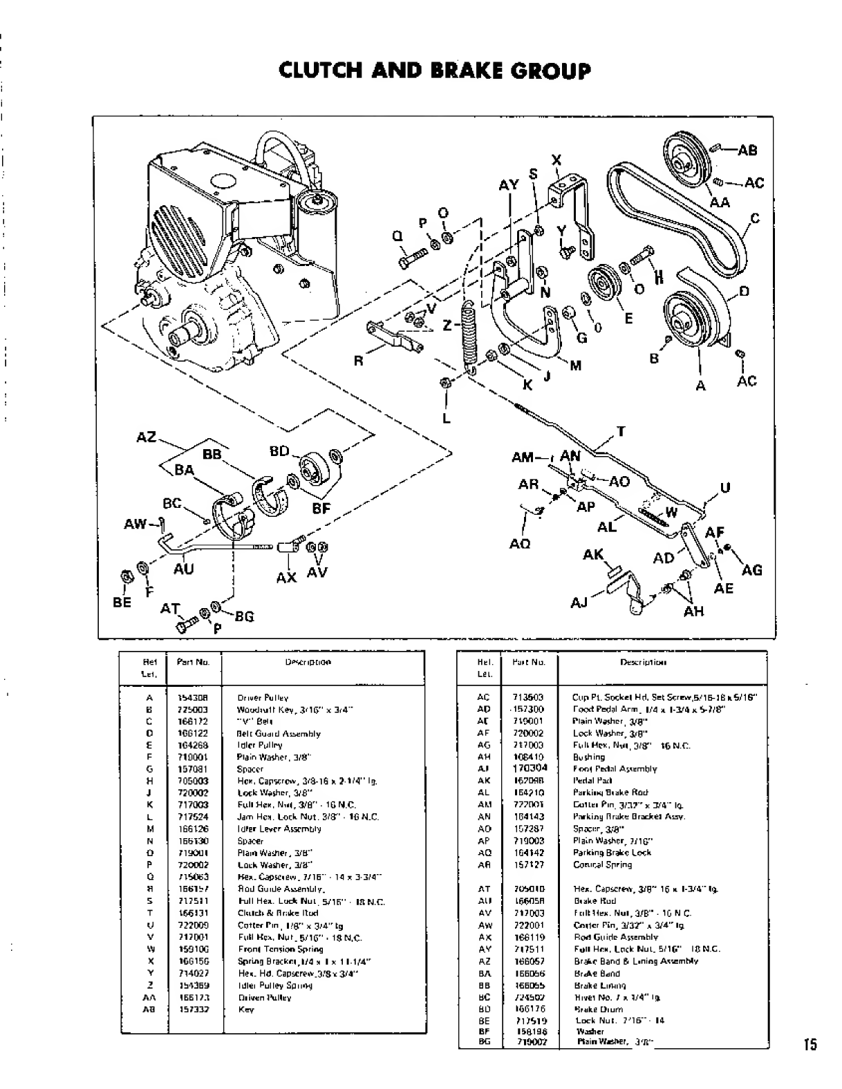
CLUTCH
AND
BRAKE
GROUP
Hel
Lai,
Pirl
Nli.
LJ^riptidO
A
mjDfl
Driver
Pi
May
E
775003
WOudquU
Key,
3'l&
r
'
x
3r4"
C
166172
"V"
OeH
0
16(5122
Belt
Guaid
Aiiemhly
E
16426a
Idler
Pulley
F
719001
Plain
Washer,
3/8"
G
157031
Spacer
H
705003
He*.
Capscrew,
3/3-16
k
2-1/4"
Iff.
J
720002
Lock
Washer,
3/£"
K
717003
FuIiHck,
Nii|,
3/6"
■
1GN.C.
L
717624
Jam
Hcm.
Lock
Nut.
3/3-
■
1GN.C.
M
166126
IdFar
Layer
Assrmtiiy
N
1EE130
Spacer
O
719O0I
Plain
Washer,
3/E"
P
72OO0J
Luuh
Washer,
3/E"
u
716063
Her.
CapSCiew.
771E"
■
14
*
3-3/4”
H
1E6157
Sou
Guide
AnfinlUly.
S
717E11
hull
He*.
Ludk
HuL
57IE"
■
l!t
N.C.
T
166H1
CkLlclrSi
Brake
Itud
V
722009
Cutter
Tin,
|/9
r
'
x
0M
,r
tg
V
717001
Full
Kc*.
Ngr.syic-
.
1SN.C-
W
169100
Front
Tension
Spring
X
166150
Spring
B
racket
,
m
I
x
1
l-1/4
,r
V
714027
Hes.
Ha.
Capserew.B/g
*
3/4"
1E43E9
Idlei
Pul
lev
SpmiHj
A
A
1
EE
17.1
□
liven
IVHey
AD
IE
7337
Key
—
Hal.
Lel.
Fair
Nu.
Dtser
i|ul
imi
AC
713603
Cup
Pi.
Socket
Hd.
Set
Screw,5/
1E-16
b
6/1G"
AP
■
1
E
73DO
rood
Pbdal
Arm_
|/4
a
1-3/4
n
6-7/6"
Ar
716001
Plain
Washer,
3/fl"
AF
720002
Lock
Wisher,
AG
717003
Full
Hck.
Nsn,
3
/gr'
tON.C.
AH
10E410
Bushing
AJ
1
70304
Foot
Fertnl
AssEmhly
AK
I67D9E
l^edal
Foil
AL
IE4J1Q
ParkiiKj
Hiake
Rod
AM
777001
DulLai
Pm
3/37
r
x
324
"
la
AN
104143
Pnrkiisg
Brake
Bracket
Assy.
AO
157237
Spacer,
3vfl"
AP
719003
Plain
Washer,
J/10
r
'
AQ
164142
Parking
Brake
Lock
Afi
157127
Coniral
Spring
AT
J1MIQ
He*.
Capscrew,
3/0"
16
*
1-3/4
"
1
$.
All
1660ER
□
lake
Hud
AV
717003
Frill
He*.
Nul,3/B"
■
10
N
C-
AW
722001
COtlcr
Pin,
'HW
*
3/4
,r
Ig
AK
166110
Rovl
Gtiidc-
AsSEmhly
AV
717511
Foil
Hon,
Lock
NuL.
5/If
ICN.C.
AZ
166067
Brake
Band
6
Lining
AssemMy
BA
IEED66
BrJkE
Hdi’id
BE
10E066
Brake
LuViii'd
EC
/24BE7
HivEI
NO.
7
r.
1/4"
lj
ED
160176
*3rabE
DiuiTi
SE
717610
Luck
Nur.
7-
,
1
6
”
■
14
BF
150196
W
jailer
EG
710002
Plain
Wester,
3
f
Jl'"
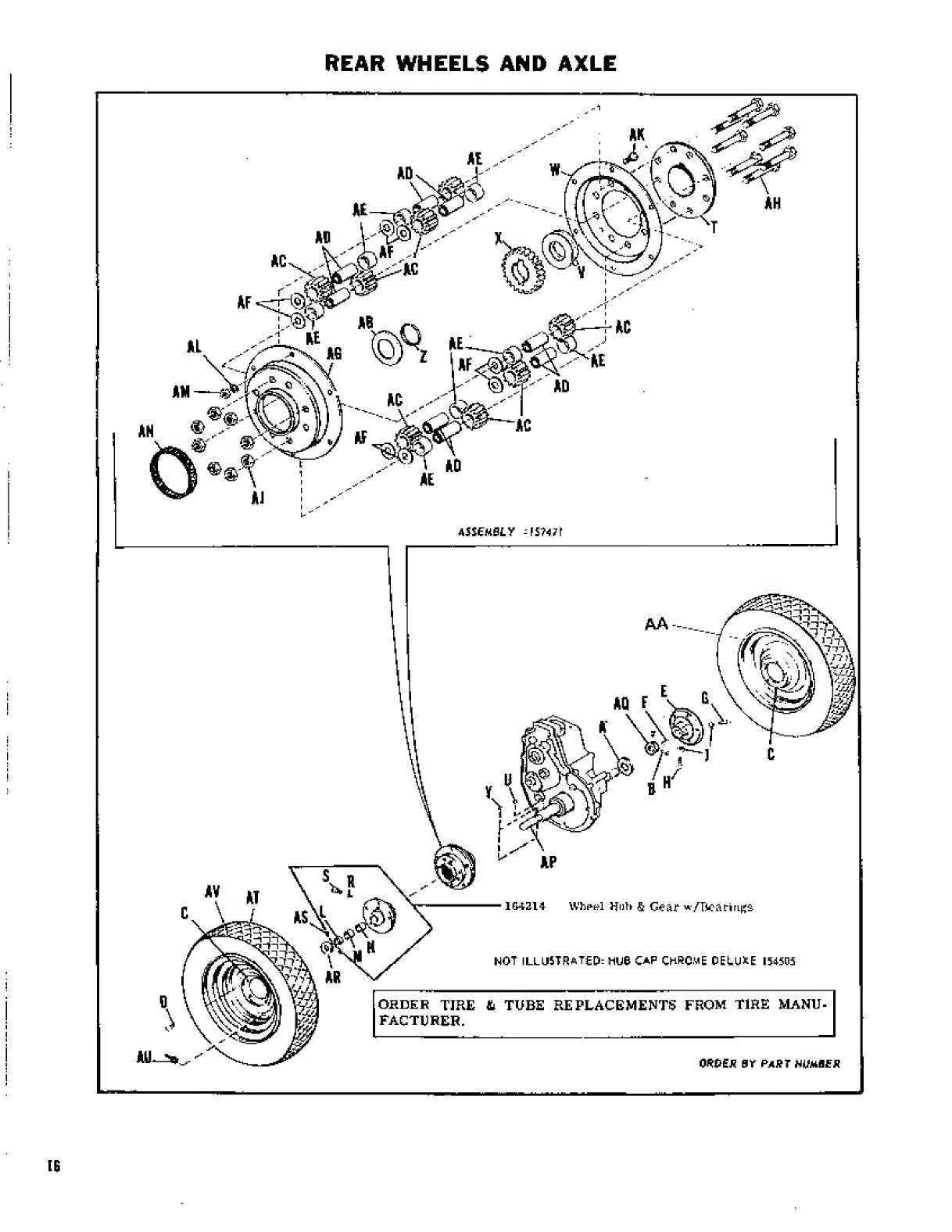
REAR
WHEELS
AND
AXLE
s\f
\"4
H
f
v
w\
164214
\Vhpt?l
Hub
fi
Gear
w/Bearings
NOT
ILLUSTRATED:
HUG
CAP
CHRC.uE
DELUDE
154505
;
ORDER
TIRE
&
TUBE
REPLACEMENTS
FROM
TIRE
MANU¬
FACTURER.
OWES
BY
PART
HUMBER

REAR
WHEELS
AND
AXLE
Ref.
Let.
Part
No.
Description
A
105050
Washer
B
713002
Set
Screw,
5/16"-18
X
3/8"
Lg.
C
170278
Wheel
Drive
D
131138
Hub
Bolt
E
154208
LH
r
Wheel
Hub
F
159129
Key
G
715022
Set
Screw,
3/8"-16
x
1
1/2"
Lg.
K
7T3004
Set
Screw
3/8"-16
x
1"
Lg.
J
717021
Hex.
Jam
Nut,
3/8"-16
i_
10505B
Bearing
M
152041
Nylon
Bearing
N
153083
Bearing
R
152042
Nylon
Plug
5
713508
Control
Traction
Bolt,
7/16"'20
x
1/2"
Lg.
T
164217
Differential
Carrier
U
157120
Drive
Key
V
154035
Axle
Washer
w-
1G4213*
Differential
Cover
X
1G4219
Differential
Gear
Y
725501
Hi-Pro
Key
z
154291
Retaining
Ring
AA
157638
Tube
(For
Service
Only)
AB
154277
Axle
Washer
AC
121311
Differential
Pinion
AD
1210B3
Pinion
Differential
Spindle
AE
1210B4
Differential
Spacer
AF
719002
Plain
Washer
AG
16422
(T
Differential
Cover
AH
715043
Hox.
Cap
Screw,
3/8"
1G
x
2
1/2”
AJ
717510
Full
Lock
Hex.
Nut,
3/8"-16
AK
705015
Hex.
Cap
Screw,
1/4"-2C
x
5/8"
AL
720003
Lock
Washer,
1/4"
AM
717005
Full
Hex,
Nut,
1/4"^20
AN
T21190
Differential
Cover
Seal
AP
164221
Rear
Axle
AQ
154055
Axle
Collar
AR
154065
Axle
Collar
AS
713002
Set
Screw,
5/1G"-18
x
3/8"
AT
157637
Tire
10
1/2"
x
12
AU
157020
Valve
Stem
AV
170280
Wheel
&
Tire
Assy.
—-CAUTION
'
‘
‘
-—
-
DO
NOT
EXCEED
2&ft.
POUNDS
OF
TORQUE
ON
PART
NUMBER
7135CS.
REFERENCE
LETTER
(5},
CONTROL
TRACTION
BOLTS.
Reference
let
Cert
"W"
and
m
A
g"
must
be
replaced
in
pairs

if££JfJNC
GEAR
CLEARANCE
ADJUSTHENT
FRONT
WHEELS,
AXLE,
TIE
ROD
&
STEERING

FRONT
WHEELS,
AXLE,
TIE
ROD
&
STEERING
Ref.
Let.
Part
No.
Description
A
157505
Wheel
and
Tire
Assembly
B
154307
Bearing
Cone
w/seal
c
154303
Bearing
Cup
.
D
1081
SI
Washer
E
157506
Wheel
w/Bearing
Cup
F
157490
Tire
G
153038
Tube
H
157494
Spindle
Assembly,
R.H.
J
157611
Spindle
Assembly,
L.H,
K
8061012
Washer
L
8021010
Set
Collar
M
713503
Cup
Point
Socket
Head
Set
Screw,
5/16"-18
x
5/16"
Lg.
N
8021010
Set
Collar
P
727001
Grease
Fitting
Q
167616
Axle
Assembly,
Front
R
157618
Spacer
s
719004
Plain
Washer,
1/2"
T
705037
Hex.
Cap
Screw,
1/2"-13
x
1"
Lg.
U
717518
Full
Lock
Hex.
Nut,
1/2"-13
V
705016
Hex.
Cep
Screw,
3/B"-16
x
1
1/4
,J
Lg.
w
710001
Plain
Washer,
3/8"
X
154177
Spacer
Y
720002
Lock
Washer,
3/8'*
z
717003
Full
Hex.
Nut,
3/8'-16
AA
154280
Bearing
AB
157013
Arm
Assembly.
Steering,
L,H.
AC
71300S
Screw,
Set
Cup
Point,
Square
Head,
5/16"-18x
1/2"
Lg.
AD
157427
Key
AE
717528
Full
Hex.
Lock
Nut,
1/2"-2Q
AG
164272
Ball
Joint
AH
164271
Tie
Rod
AJ
717010
Nut,
1/2"'20
N.F.
AK
157702
Steering
Wheel
AL
725003
Woodruff
Key
No.
9
Ref.
Let.
Part
No
r
-
———“-
■
-
Description
AM
713503
Socket
Head
Cup
Point
Set
Screw,
5/16"-18x
5/1G"
Lg.
AN
713502
Socket
Head
SetScrew,
E/16"-18
x
1/4"
Lg.
AP
157259
Steering
Shaft
Assembly
AG
153081
Spacer
AR
719001
Plain
Washer,
3/S"
AS
720002
Lock
Washer,
3/B"
AT
715030
Hex.
CapScrew,
3/8"-1G
x
3/4"
Lg.
AU
154153
Universal
Joint
Pin
AV
157254
Bushing
Assembly
AW
157268
Bushing
AX
157253
Pin
Eccentric
AY
158399
Retainer
Ring
AZ
720002
Lock
Washer
BA
717003
Full
Hex.
Nut,
3/8^16
BB
713012
Sq.
Hd.
Set
Screw,
1/4"-20
x
3/4"
BC
157302
Steering
Bracket
BD
154258
Needle
Searing
BE
720001
Lock
Washer,
5/16"
BE
705012
Hex.
Cap
Screw,
5/16"-18x
5/8"
BG
8861012
Washer
BH
164263
Steering
Arm
Assembly
BJ
164235
Gear
Steering
BK
188182
Arbor
Washer
BL
154487
Hub
Cap
BM
717519
Gripco
Center
Lock
7/16"-14
BN
715026
Hex
Cap
Straw
BP
717511
Full
Hex.
Nut,
5/16"-ia
BG
154264
Snap
Ring
BR
15728G
Retaining
Ring
BS
157499
Drag
Link
BT
154486
Outside
Bearing
BD
157305
Valve
Stem
BV
157077
Steering
Bushing
IS
This manual suits for next models
1
Table of contents


