Sp Air Construction Series User manual

Instruction and Maintenance Manual
3 Phase - Belt Driven Compressors
IMPORTANT ─
──
─Make certain that persons who are to use this equipment thoroughly
read and understand this Instruction Manual prior to operation.
PV0614

1
CONTENTS
Chapter 1 Technical Specifications
1.1 Parts and Features …………………..………………………………….……3
1.2 General Information …...…………………………………..…………………4
Chapter 2 Operating the Air Compressor
2.1 Important Safet Instructions …...…………..……….…………...…………8
2.2 Preparation Before Starting ….……..…………………………………….…9
Chapter 3
Maintenance of the Air Compressor
3.1 Regular Maintenance ……...……………………………...…………....…14
Chapter 4 Trouble-Shooting for the Air Compressor
4.1 Trouble-Shooting ………..……………………………………….……….…17
Appendixes
Limited Warrant Polic ………..………………….………………….…………23
Please read and understand this manual before operating the compressor. Failure to do so could result in
death, severe injur and/or substantial propert damage.
This manual should be considered a permanent part
of the compressor and should remain with it if resold.

2
NTRODUCT ON
This Owner’s Manual is intended to compl with all Australian Occupational or Workplace Health and Safet
Regulations regarding the manufacturer’s provision of information to the owner or purchaser of work plant. The
information is correct at the date of publication.
APPL CAT ON
Your air compressor is a single stage, oil lubricated, and air cooled reciprocating air compressor. It is t picall
supplied as a compact, self-contained, air receiver (tank) mounted unit that is automaticall regulated and driven b
a 3 phase electric motor.
The compressor is intended to provide compressed air in a multitude of applications, for example, to power
pneumatic tools, operate air dusters and spra guns, inflate tires, and suppl air for pneumatic valves and actuators.
It is commonl used as the primar source of compressed air for home garages, workshops, service stations, t re
shops, factories, farms, mobile service vehicles, and so on. Supplementar duties can include furnishing
compressed air at an isolated location not serviced b the regular shop air s stem, and standb service when
larger compressors are shut down.
Air discharged from an oil lubricated compressor t picall contains small amounts of oil, water and particulates
amongst other contaminants. Virtuall all applications require treatment of the compressor’s output air to make it
suitable for the end use. Air qualit treatments such as filtration and dr ing are the most common requirements
together with pressure regulation. The use of compressed air lubricators to protect pneumatic tools is also
commonplace nowada s. Failing to install appropriate compressed air treatment equipment will likel result in
damage to pneumatic machiner or spra painted finishes.
Where installed, compressed air filtration and/or dr ing equipment should be located downstream from the air
receiver tank and ahead of an pressure regulator. Lubricators, on the other hand, should be installed as the last
stage of treatment and located behind or downstream from an pressure regulator.
FUNCT ON
The pressure switch turns on the motor when the air receiver tank is at or below the minimum “cut-in” pressure.
The compressor then runns until the tank pressure reaches the maximum “cut-out” pressure whereupon the
pressure switch turns the motor off. Air will then be heard (for some seconds), escaping from the unloader valve
(in the base of the pressure switch) releasing residual air pressure in the discharge pipe and on top of the pistons in
the compressor pump. Thereb allowing the compressor to re-start easil , when next required.
The pressure switch is factor preset with cut-in and cut-out pressures of approximatel 120 psi and 150 psi,
respectivel . This range is ideal for the vast majorit of compressed air applications as most pneumatic tools have
been designed for use with a suppl (line pressure) of 90 psi. (6bar). Unless necessar for a special application,
line pressures of more than 90 psi. (6bar) are not recommended.
In the event that a pressure switch were to fail to turn the motor off at the prescribed cut-off pressure, then the
safet valve will protect the air receiver tank against over pressurizing b automaticall releasing air when the
pressure exceeds its preset value (ie 150psi [10bar]) . Air receiver tanks are designed and manufactured to
satisf the requirements of Australian Standards and all Australian Occupational or Workplace Health and Safet
Regulations.
3
Chapter 1
Parts & Features
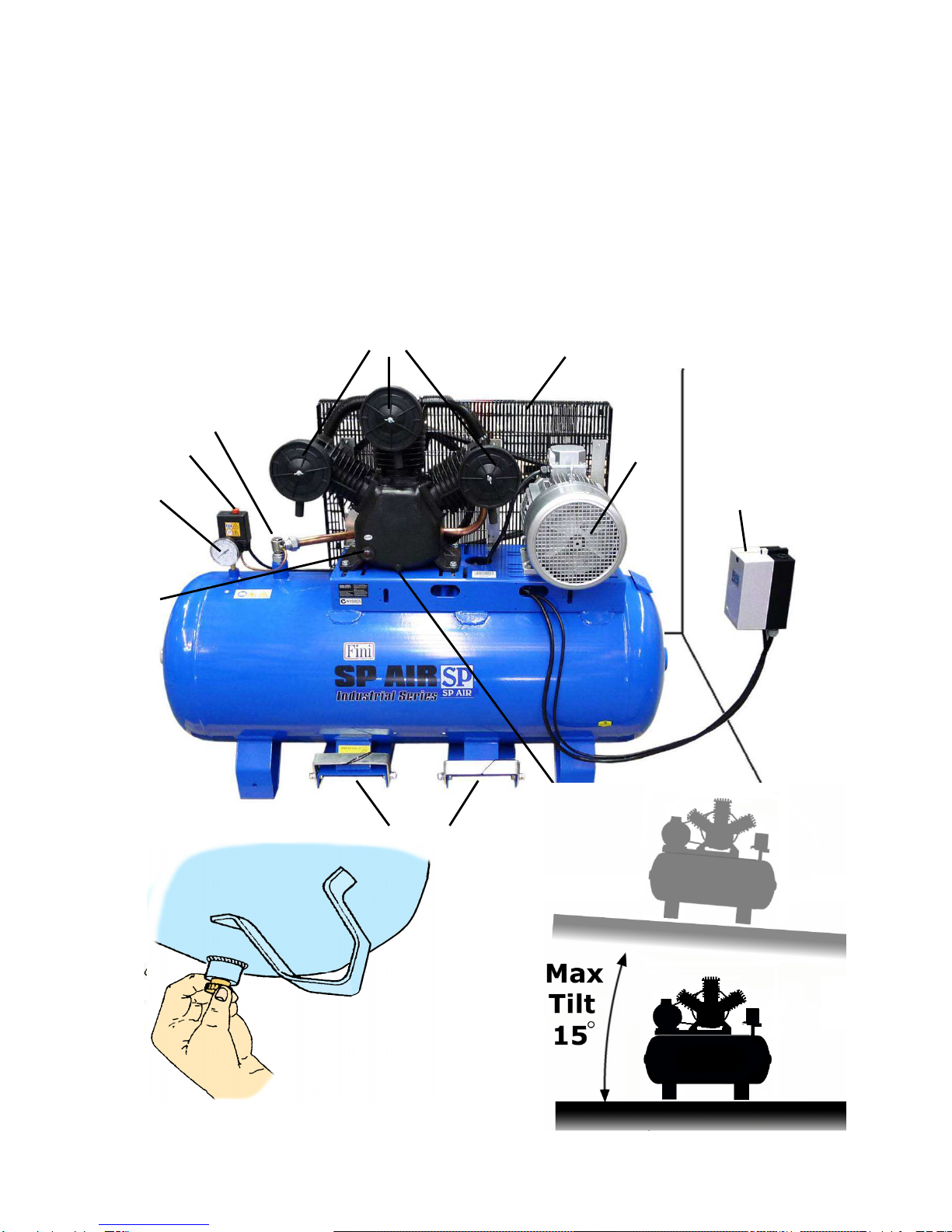
DESCR PT ON
(1) Oil level sight glass (6) Safet cage
(2) Tank Pressure Gauge (7) Electric motor, air intake
(3) Pressure Switch On / Off (8) 3 phase contactor (wall mount)
(4) Non Return Valve (NRV) (9) Oil drain bung
(5) Air filters (10) Lifting Points
MPORTANT ─ mproper operation or maintenance of this air compressor could
result in serious injury and/or property damage, thoroughly read and
understand this nstruction Manual prior to operating the air compressor.
8
2
2
4
10
6
1
5
3
9
7

4
Sight glass
-
Check
Daily
The compressor oil level can be viewed through the sight
glass; the compressor must be on a level surface.
The top of the red dot indicates the full mark the bottom of
the red dot indicates the low mark. Alwa s ensure that
the oil level is correct before operating the compressor.
If the oil is low add Scorpion Compressor oil
or equivalent Aircol PD68.
Drain air tank – Daily
A drain valve is fitted to the bottom of the air receiver tank to permit the release of water condensation that
would otherwise corrode the tank and damage pneumatic devices.
Loosen the drain nut and allow an condensed water to escape, once all the air and moisture has been
released, finger tighten onl the drain valve.

5
Don’t Turn the Compressor on and off at the Wall
Use the Pressure switch – On / Off
The pressure switch automaticall controls the power to the motor and
operates the pressure relief valve. It also allows for manual operation via
the Push/Pull - On/Off switch on top of the pressure switch.
The pressure switch is factor set to turn the compressor on when the tank
pressure drops below 120 psi and turn itself off again when the tank is full.
You will notice that ever time the unit reaches maximum pressure and
turns itself off (or if the unit is manuall turned off); there is a short release
of high pressure air from under the pressure switch.
This is the pressure relief valve venting the air contained within the deliver
tube (the pipe which connects the compressor pump to the non return
valve). Failure to vent the pressurized air between the pump and the tank
will cause excessive current draw on startup which ma lead to motor
failure. For this reason alwa s turn the compressor On and Off via the
pressure switch.
The delivery tube:
Supplies compressed air
from the pump to the tank.
Only Operate the Compressor on a Flat Surface
Maximum Tilt
The maximum safe operating angle in an direction is 15° degrees.
Do not operate the compressor on inclines in excess of 15° degrees. Serious damage to pump components ma result
from insufficient lubrication.
Never use the air compressor on a rooftop or elevated position that could allow the unit to fall or be tipped over.
Alwa s disconnect the power before moving.
The pressure relief valve:
Vents pressure when the
unit is turned off.
The Non Return Valve:
Prevents any back flow from the tank.
6
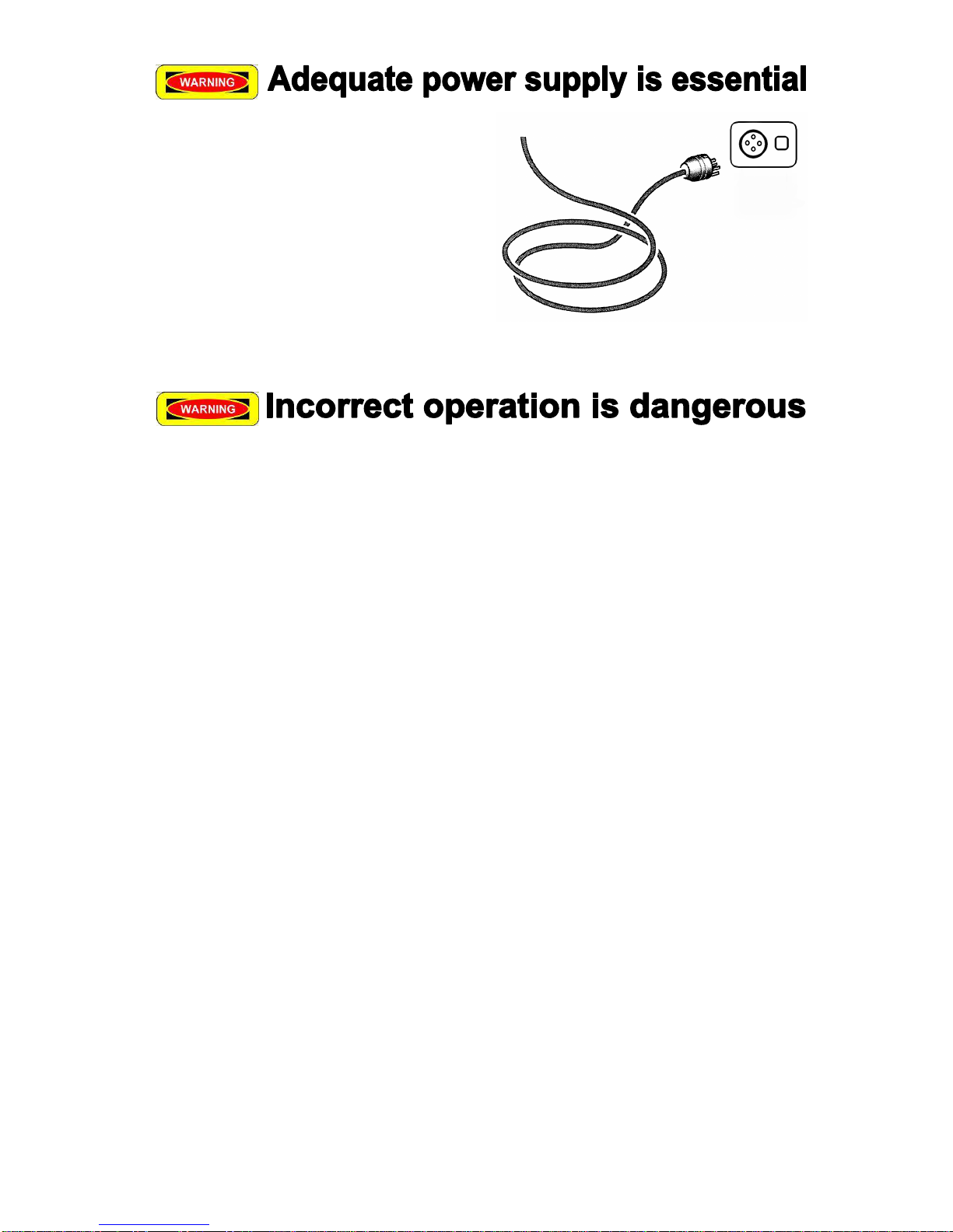
Power supply
/ 3 phase
, 50Hz
It is essential that the air compressor has an adequate
power suppl .
The air compressor should be operated on a dedicated
3 phase 415 volt circuit.
The compressor must be connected to a properl
grounded circuit of adequate capacit .
•Should ou intend to use an air tool for a long durations ensure that the out put of the compressor (know as the
FAD or Free Air Deliver ) well exceeds the air consumption of the tool being used.
•Remember that our compressor has been designed with a 50% dut c cle in mind; continuous operation ma
cause it to overheat and result in serious mechanical damage to pump components. You should consider a
larger or screw t pe compressor for long term or continuous dut applications.
•
Do not use extension cords
. Using an extension lead on a compressor can cause voltage drop,
overheating the motor and leading to appliance damage or even fire.
•As our Compressor has an air cooled motor as well as an air cooled pump which draws in atmospheric air it is
important not to run the compressor in confined areas with poor ventilation or on loose surfaces such as dirt,
dust or sand, otherwise abrasive particles will be sucked into the air stream and cause the premature wear of
components.
•Your air compressor is not water proof; do not attempt to use or store it in the rain, snow or an other
environment with extreme conditions. It has been designed for use and storage indoors.
•Used and maintained correctl , our Compressor will provide man ears of reliable service.
•Your Compressor has been manufactured to a high standard in order to ensure a long service life. Ultimatel
the realization of the intended service life requires the operator to observe all instructions and servicing
requirements as described in this manual.
•Alwa s wear approved protection equipment such as safet glasses with side shields, ear muffs and gloves
when operating the compressor or using compressed air. Wear a face mask or respirator when spra ing,
blowing down or otherwise creating airborne mists or dust.
•Never point an nozzle or spra er toward an part of the bod or at other people or animals.
•Do not operate the air compressor if an guards or covers are missing, damaged or not installed correctl as
the compressor ma start automaticall . Ensure all maintenance is carried out b qualified personal.

7
•Never allow children, pets or untrained personal to “pla ” with compressed air.
•Keep children, pets or unauthorized personal awa from the compressor at all times.
•Compressed air can contain carbon monoxide, h drocarbons and/or other poisonous contaminants that can
cause death or serious injur . The air compressor is not designed, intended or approved for breathing air. Do
not use compressed air for breathing air applications without proper treatment. Do not use the compressor for
an gas other than air.
•
High voltage electricit can cause death or serious injur . All electrical installation or repair work must be
carried out b a licensed electrician.
• D SCONNECT POWER SUPPLY BEFORE SERV C NG.
•Do not stand on the compressor or use it as a handhold.
•High pressure air can cause death or serious injur . Do not b pass, modif or remove the safet valve. Do
not operate the compressor with a fault safet valve or pressure gauge.
•Do not direct the air stream at bod , high pressure air can stir up dust and debris that ma be harmful.
Release air slowl when draining condensation or depressurizing the compressor. Do not connect the
compressor to air handling equipment that cannot withstand the compressor’s maximum design pressure (refer
to the tank nameplate).
•Rusted, cracked or damaged air receiver tanks can explode and cause death or serious injur and must be
replaced. Drain tank dail or after each use through the valve located at bottom of the tank.
•Release compressed air from tank before servicing, do not weld drill or otherwise modif the air receiver tank.
•Do not spra flammable liquids in a confined area. Do not smoke while spra ing where sparks, flames or
other ignition sources (including the compressor) are present.
•Do not direct paint or other spra ed material at the compressor. Locate the compressor as far awa from the
spra ing area as possible to minimize overspra accumulating on the compressor and/or clogging it’s air filters.
•Motors, electrical equipment and controls can cause electrical arcs that ma ignite a flammable gas or vapor.
Do not operate or repair the compressor in or near a flammable gas or vapor. Do not store flammable liquids
or gases in the vicinit of the compressor.
•Before attempting to install, maintain, repair, store or transport the compressor, switch off the unit, tag and lock
out the power suppl and carefull release all air pressure from receiver tank, air hoses and/or piping.
•Do not permit an one to operate the compressor without proper instruction.

8
Chapter 2 Operating the Air Compressor
2.1 MPORTANT SAFETY NSTRUCT ONS
MPROPER OPERAT ON OR MA NTENANCE OF TH S PRODUCT COULD RESULT N SER OUS
NJURY AND OR PROPERTY DAMAGE.
READ AND UNDERSTAND ALL WARN NGS AND OPERAT NG NSTRUCT ONS BEFORE US NG.
HAZARD
WHAT CAN HAPPEN HOW TO PREVENT IT
Water directed at electrical
connections or switches, or objects
connected to an electrical circuit,
could result in a fatal electrical shock.
Moisture or a liquid of an kind ma
conduct electricit and could result in
a fatal electrical shock.
The air compressor is not
waterproof.
Never attempt to clean the air
compressor while it is running. Direct
an water or spra awa from electric
outlets and switches.
Keep our air compressor out of the
elements and well sheltered from rain,
snow, dew, water or mist of an kind.
Do not use the compressor with the
suppl cord damaged or with poor
qualit connections.
0.5m
Operating the
air compressor
in an
explosive environment could result in
a fire.
Materials placed against or near the
air compressor can interfere with its
proper ventilation causing overheating
and possible ignition of the materials.
Improperl stored paint thinners could
lead to accidental ignition. Thinners
improperl secured could get into the
hands of children or other unqualified
persons.
Good air flow is important as both the
motor and compressor unit are air
cooled. Restrictions to or insufficient
air flow will cause overheating.
Never spra paint in
a confined area
with the air compressor.
Operate the air compressor in well
ventilated areas free from
obstructions. Equip areas with fire
extinguishers suitable for electrical
fires. Do not leave n lon material
shirts or jumpers on the compressor.
Store paint thinners and other
flammable liquids in approved
containers, in a secure location awa
from the work area.
Minimum clearance 0.5m
Maximum ambient operating
temperature 45°C
This air compressor doe
s
not provide
breathable air; the air ma be
contaminated with mineral based oils
and other contaminants which poses
the risk of serious lung infection and or
injur .
Spra ing an material without the use
of a face mask will result in the
ingestion of foreign substances.
Never tr to provide brea
thing air or
refill auxiliar breathing apparatus
using this compressor.
Never spra substances in a closed
location occupied b humans or
animals alwa s use a face mask
when spra ing substances.
Contact with hot surfaces, such as
the
c linder head, cooling fins or
discharge pipe, could result in serious
burns.
These parts will remain hot for some
time after the compressor is shut
down.
During operation, touch onl the
control surfaces of the air
compressor. Keep children and
animals far awa from the air
compressor at all times. The ma not
be able to recognize the hazards of
this product.
Allow the air compressor to cool
before storage.
9
2.2 Preparation before Starting
RECE PT AND NSPECT ON
Ensure that adequate lifting equipment is available for unloading and moving the air compressor to the installation site.
Lifting equipment, slings, etc. must be properl rated for the weight of the compressor.
Lift the compressor from the deliver vehicle b the shipping pallet onl . Do not use the electric motor lifting e ebolt to lift
the entire compressor. The motor lifting e ebolt is onl to be used for removing the motor from the compressor unit.
Do not work or walk under the compressor while it is suspended in the air.
Inspect the compressor upon receipt for an shipping damage or missing parts.
•If an problems are apparent, make an appropriate note on the deliver receipt before signing, then contact
our dealer immediatel .
•Do not operate unit it has been damaged during shipping.
•Read the compressor model label to verif it is the model ordered.
•Check the motor nameplate to verif that it is compatible with the available electricit suppl .
•Make sure that electrical enclosures and components are appropriate for the installation environment.
UNPACK NG
Remove the carton and plastic bag that covers the
compressor. Ensure that children do not pla with the
plastic bag as it is a breathing hazard. Unbolt the
compressor from the shipping pallet. Do not use the
timber shipping pallet for mounting the compressor.
Using a forklift, lift off the shipping pallet using the lifting
points onl and place it close to the 3 phase power outlet.
Fit the air filters and add oil to the pump as necessar .
Fit air tap to end of tank and connect to air suppl line
We recommend that ou store the packaging for the
duration of the warrant period. If necessar , it will be
easier to return the compressor to the service center.
L FT W TH CARE AS THE COMPRESSOR S TOP HEAVY
NSTALLAT ON
Select a clean, dr and well lit area most preferabl indoors with plent of space for proper ventilation, cooling air flow
and accessibilit . The air compressor is designed for operation in ambient temperatures of between 0°C (32°F) and
40°C (104°F). Locate the compressor at least 500 mm from walls for adequate air cooling and to allow for
maintenance access. Ensure that the power suppl is clearl identified and accessible. Alwa s provide sunshade and
shelter from moisture if the compressor has to be located outdoors.
Bolt the compressor to a firm, level foundation such as a concrete floor that is strong enough to support its weight. Do
not bolt uneven feet tightl to the foundation as this will cause excessive stress on the air receiver tank. Use metal shims
to pack under an “short” feet, if necessar . The use of flexible vibration isolators underneath the mounting feet is highl
recommended and will reduce noise emissions.
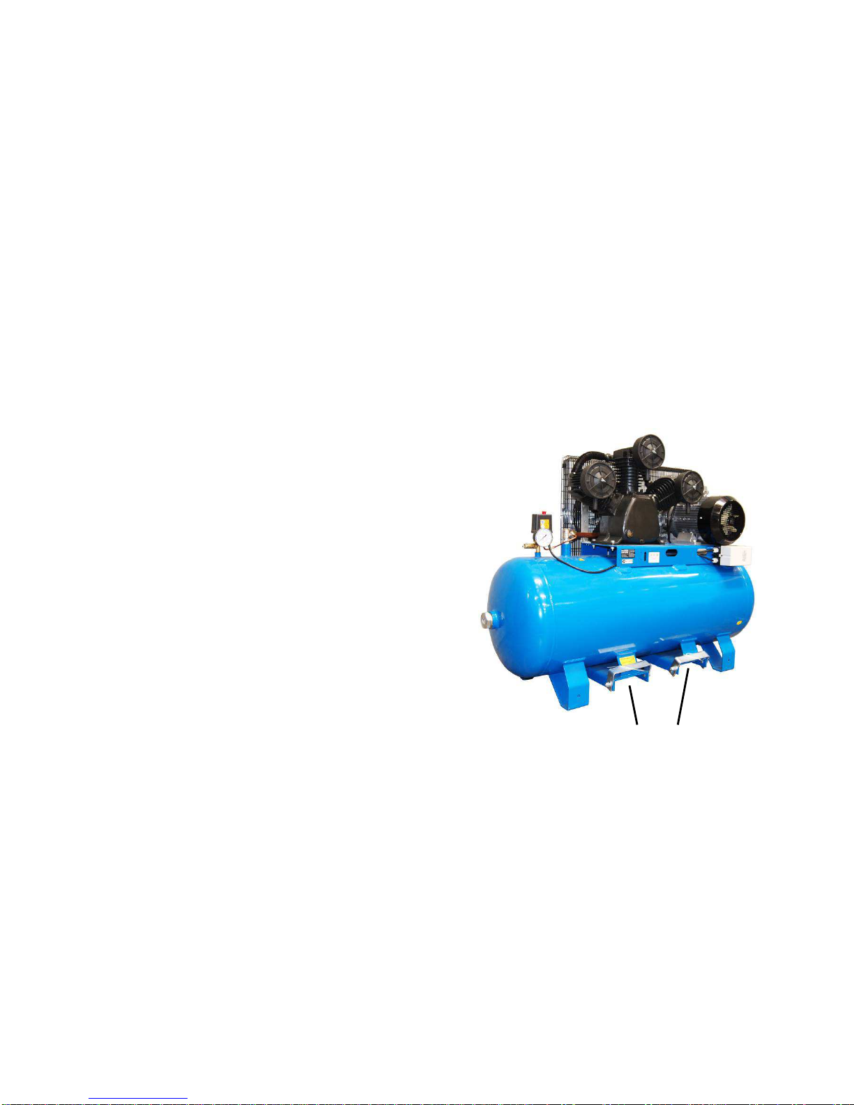
L FT NG PO NTS

10
Noise Considerations
Check the State Workplace Health and Safet Regulations and/or Local Council regulations regarding acceptable noise
levels. To reduce excessive noise, use vibration isolators, relocate the compressor or construct an enclosure or baffle
walls.
Discharge Piping
All piping, fittings, air receiver tanks, and so on connected to the compressor discharge must be certified safe for the
unit’s discharge pressure and temperature. Do not use PVC plastic in the compressed air discharge line. Use pipe
thread sealant on all threads and assemble joints tightl to prevent air leaks and energ wastage.
Mainline piping used to conve air throughout a s stem should be sized to accommodate the maximum flow rate of the
compressor (also referred to as it’s free air deliver ) in accordance with Table 1. Branch piping should be sized in a
similar manner, but the design flow rate should instead be based on the total air consumption of the tools or appliances
running off that branch. To allow for vibration and to prevent piping stresses being transmitted to the
compressor, the connection between the unit’s discharge valve and the mainline piping s stem should be made using a
flexible air hose or coupling.
Table 1
RECOMMENDED P PE S ZES FOR COMPRESSED A R L NES
LENGTH OF P PL NE (METRES)
FL
OW
L/M N 7.5m 15m 22.5m 30m 45m 60m 75m 90m
142
½”
½”
½”
½”
¾”
¾”
¾”
¾”
283
½”
½”
½”
¾”
¾’
¾”
¾”
¾”
425
½”
¾”
¾”
¾”
¾”
¾”
¾”
¾”
566
¾”
¾”
¾”
¾”
¾”
¾”
¾”
¾”
708
¾”
¾”
¾”
¾”
¾”
1”
1”
1”
849
¾”
¾”
¾”
¾”
1”
1”
1”
1”
991
¾”
¾”
1”
1”
1”
1”
1”
1”
1132
¾”
1”
1”
1”
1”
1”
1”
1”
1670
1”
1”
1”
1”
1”
1”
1”
1”
2236
1”
1”
1”
1”
1
-
1/4”
1
-
1/4”
1
-
1/4”
1
-
1/4”
2830
1
-
1/4”
1
-
1/4”
1
-
1/4”
1
-
1/4”
1
-
1/2”
1
-
1/2”
1
-
1/2”
1
-
1/2”
Air hose should be sized in accordance with Table 2, and again with consideration as to whether the hose is a
distribution line or a branch line.
Table 2
RECOMMENDED HOSE S ZES FOR COMPRESSED A R L NES
LENGTH OF HOSE (METRES)
FLOW
L/M N 7.5m 15m 60m
566
3/8”
3/8”
½
”
849
3/8”
½”
½”
1698
½”
¾”
¾”
11
ELECTR CAL CONNECT ON
This work must be carried out by a licensed electrician.
All 3 phase compressor are not supplied with a power lead or plug. A licensed electrician is required to wire up the
compressor from the wall mounted contactor box, to a dedicated 3 phase electrical outlet, either with a four pin plug or
hard-wired into the electrical suppl . The circuit must be of adequate capacit and fitted with a circuit breaker.
Mount the contactor box to the wall as close to the compressor as practical.
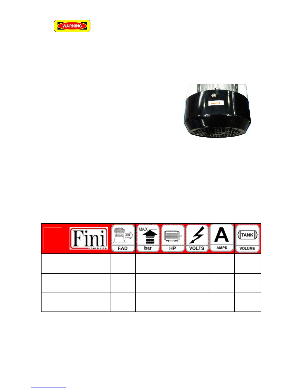
Ensure correct direction of rotation
:
The installing electrician must ensure that when wired in, the motor
is turning in the correct direction. Failure to obtain the correct
direction of rotation will prevent the fan / fl wheel from delivering
the necessar air cooling across the pump.
Electrical Connection
All electrical installation and service work must be performed b a licensed electrician in accordance with all applicable
regulations. The electric motor rating as shown on the motor nameplate and the power suppl must have compatible
voltage, phase and frequenc characteristics.
The required size of electrical wiring between the power suppl and the electric motor varies according to motor power
and other factors, use the table below to understand what power is required to operate each size Compressor.
Adequatel sized wiring must be installed to protect against excessive voltage drop during compressor start-up and
running. If connecting other electrical equipment to the same circuit, consider the total electrical load when selecting
the proper wire size. Overheating, short circuiting and fire damage ma result from undersize wiring.
NB Portable electric generators are not recommended for operating compressors unless the have ample generating
capacit to provide the requisite starting and running currents without appreciable voltage or frequenc drop.
Model:
XRS25
Piston Compressor
50% duty cycle
453L/PM
10 Bar
(150 psi)
5.5 HP
(4 KW)
415V
(3 Phase)
8AMPS
(per Phase)
200 L
XRS35
Piston Compressor
50% duty cycle
708L/PM
10 Bar
(150 psi)
7.5 HP
(5.6 KW)
415V
(3 Phase)
10AMPS
(per phase)
270 L
XRS50
Piston Compressor
50% duty cycle
1132L/PM
10 Bar
(150 psi)
10HP
(7.46 KW)
415V
(3 Phase)
13.5AMPS
(per phase)
270 L

12
OPERAT ON
Before operating the air compressor, alwa s check first to ensure that it has been received, inspected and installed in
accordance with the instructions herein. Rectif an discrepancies before proceeding further.
Check the compressor pump oil level b looking at the sight glass. The oil level should be at the top of the red circle on
the oil sight glass. Add oil, if required, through the oil fill cap and onl when the unit is not operating. Do not overfill with
oil. Refer to the Maintenance and Repair section for recommended oil specifications. Check that the outlet valve, if fitted,
is closed. An connected air hose(s) and/or distribution pipe(s) should not be open to the atmosphere. This is to prevent
an injuries from “hose whip” and/or high pressure air discharge and also to avoid unattended compressed air discharge
to the atmosphere. In the event that an air line is cut or broken, the air suppl must be immediatel closed off at the
compressor either b shutting the discharge outlet valve or switching off the compressor. Do not attempt to “catch” the
loose end of a discharging air hose.
Check that the tank drain valve is closed. Take care when discharging air from the tank, i.e. from the safet valve, the
drain valve or the air outlet, to ensure that it does not cause dirt, stones, metal swarf or other particles to be blown
around.
An unusual noise or vibration likel indicates a problem with the compressor. Do not continue to operate the unit until
the source of the problem has been identified and corrected.
Duty Cycle
To maximize service life, the air compressor should be adequatel sized for its given application. It should ideall
operate in a repeating run-stop or pump-unload c cle, with total compressor “pumping” time not exceeding 50% or 30
minutes in ever hour on average. The elapsed time between the start and finish of an given pumping c cle (i.e. the
continuous duration that the electric motor operates) should not exceed 30 minutes. If the unit cannot suppl the
compressed air demand without exceeding the above dut c cle limits, then either the demand should be reduced or the
compressor should be replaced with a larger unit having greater free air deliver .
The dut c cle limit is intended to protect the compressor pump valves and heads against stabilized high operating
temperatures that can cause premature pump failure.
Run in procedure
When starting for the first time leave the air compressor run for 10 minutes without load, leave the air cock completel
open. After 10 minutes check that the drain cock is closed and shut the main air cock. As tank pressure increases
check that the compressor stops automaticall once maximum pressure is reached.
*Note: All compressors are delivered onl after a successful testing period at the factor .
For the long life of our compressor it is recommended that ou drain and replace the pump lubricant
after 10 hours
of use,
Drain the oil while it is still warm this will help remove an abrasive particles loosened from the initial run in
period. Replace pump oil with Scorpion Compressor oil AC-68.
13
Optional Accessories
(not standard equipment)
Air Dryer:-
A compressed Air Dr er is a device for removing water vapor from compressed air.
The process of compressing air concentrates water vapor from the atmosphere, which raises the dew point of the
compressed air relative to free atmospheric air and leads to condensation within pipes as the compressed air cools
downstream of the compressor.
Excessive water in the compressed air suppl , either in the liquid or vapor form can cause a variet of operational
problems for users of compressed air. These include: corrosion of equipment, fouling of process lines and
contamination of jobs. Water vapor is removed from compressed air to prevent moisture entering tools and/or
interfering in sensitive industrial processes.
Refrigerated air dr ers utilize a mechanical refrigeration s stem to cool the compressed air and condense water vapor.
Refrigerated air dr ers cool the compressed air to a temperature of approximatel 1.6 degree Celsius to 10 degrees
Celsius which results in a pressure dew point range of .5 degrees Celsius to 3.8 degrees Celsius. This range permits
the pressure dew point to fall within limits that are achievable with common refrigeration s stems.
Pre and Post-Filters:
The Pre and Post- filters are designed with progressivel finer filters to limit contamination b trapping the fine particle
matter and separating this matter from the air stream.
The Pre-Filter has a 5 micron filter that will trap most of the bigger contaminates that pass from the compressor.
The Post-filter has a 0.01 micron filter and is designed to remove an finer contaminates that the Air Dr er ma have not
been able to remove.
Filter/Regulator
The filter/regulator is a pneumatic device which is comprised of a pressure regulator, a 25 micron filter and a water trap.
The regulator allows the operator to adjust the output pressure to suit the air tool that is being used.
It is suggested with this t pe of setup to have the filter/regulator mounted near to where the air tool is going to be used,
do not mount a filter regulator at the compressor as this will restrict air flow to the whole building s stem t picall the filter
regulator is fitted where the piping changes to a flexible air line.
Table 4
shows the suggested Pre-Filter, Air Dr er, Post Filter and Filter/Regulator combination that can be used for each
particular Compressor.
Table 4
Model
Pre
-
Filter
Air Dryer
Post
-
Filter
Filter/Regulator
XRS25
JF
-
C
-
001
LD05SHA
JF
-
A
-
001
SFR
-
404
XRS35
JF
-
C
-
002
LD10SHA
JF
-
A
-
002
SFR
-
404
X
RS50
JF
-
C
-
002
LD10SHA
JF
-
A
-
002
SFR
-
404
14
Chapter 3 Maintenance of the
air compressor
WHEN DO NG MA NTENANCE, YOU MAY BE EXPOSED TO ELECTR C TY, HOT SURFACES, H GH
PRESSURE A R, MOV NG PARTS, OR F RE WH CH MAY RESULT N NJURY OR DEATH. BEFORE
PERFORM NG ANY MA NTENANCE OR REPA R, D SCONNECT ANY POWER SOURCE; LET THE
COMPRESSOR AND MOTOR COOL DOWN COMPLETELY. DRA N ALL A R PRESSURE FROM THE
TANK. CONTACT A SPEC AL ZED SERV CE TECHN C AN FOR ALL ELECTR CAL REPA RS.
Before performing an maintenance or repair work on the compressor, switch off the unit, tag and lock out the power
suppl , and carefull release all air pressure from the receiver tank, air hoses and/or air piping. Use onl genuine spare
parts for maintenance and repair of the compressor to ensure its safe and reliable operation.
The maintenance schedule
shown has been developed for t pical industrial applications in clean indoor environments. The service intervals should
be shortened in harsher working conditions. Regular preventative maintenance is essential for the safet , reliabilit and
performance of the compressor and will add ears to its useful life.
3.1 Regular maintenance schedule
Keep our air compressor in good condition, regular inspection and maintenance is ver important.
Service period
regular
Item
Ever
da After 10 Hrs Ever month Ever 6 months
Ever ear
Check the oil level
Drain tank condensation
Check V belts Tension 1st time
2nd and
thereafter
Test Safet Valve
Clean air intake filter
(Service more frequentl
when used in dust
conditions)
Replace filter
element
Change pump oil 1st time
2nd and thereafter
Check bolt tensions 1st time
General cleaning of the
compressor, check for air and
oil leaks
“
”
The chart above indicates which checks to make and when to make them.
15
Check for any loose
fasteners
after
1
0 hours of operation
•Check that all nuts and bolts are properly tight
•Drain and replace the pump lubricant
Replace pump oil with Scorpion compressor oil.
(this will remove abrasive particles, from initial run in period)
After 10Hrs of use
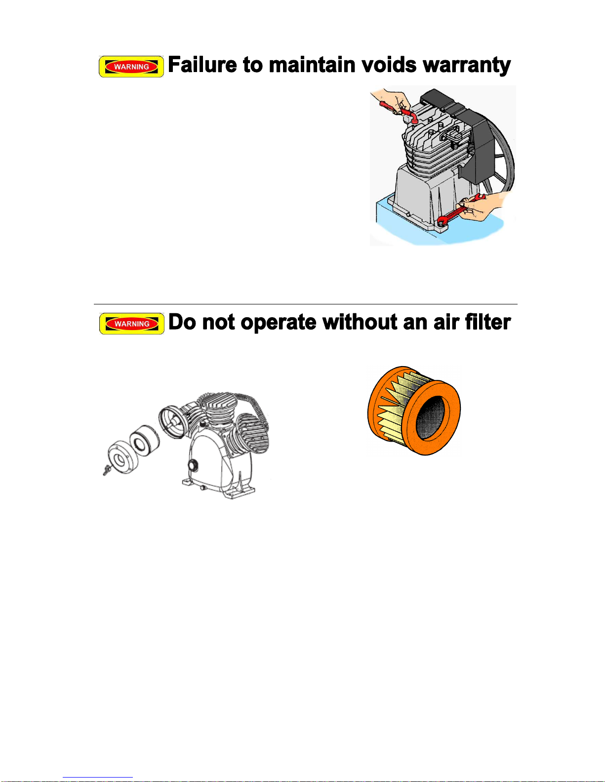
Air filter maintenance
Remove the outer cover to access the filter element
Paper air filter elements, can be cleaned b gentl
blowing with compressed air (20psi) from the inside out.
Air filter maintenance
Air filter maintenance will be increased when the
compressor is used in dust conditions.
If it cannot be blown clean or is otherwise torn or
damaged, the filter element must be replaced.
Replace the filter ever 12 months.
Do not operate the compressor without an air filter.
Foam air filter elements should be washed in warm soap
water, allow to dr , then re-oiled before use.

16
Check b
elt tension
Correct belt tension is important if the belt is too tight it will
cause the motor to overheat and increase electricit
consumption. If the belt is too loose it ma slip easil ,
whip and break.
The drive guard must first be removed before V-belt
tension can be checked or adjusted, hang a weight of
about 3kg at the mid point of the belt. Deflection should
be about 10mm.
If tension adjustment is necessar , loosen the four fasteners holding the motor to the baseplate. Then either move the
motor awa from or closer to the pump to increase or decrease V-belt tension, respectivel , and retighten the
hold-down fasteners. Alwa s use a straight edge to check that the motor
and pump pulle s are properl aligned and the V-belt(s) runs straight. Do not over tension the V-belt(s). Alwa s
refit the drive guard before operating the compressor.
Correct pulley alignment is extremely important!
Cleaning
Switch off the air compressor and use light air pressure to blow dust and foreign matter off the compressor pump, motor,
piping and air receiver tank. Oil and grease marks should be cleaned off using mild household surface cleaner and a
soft rag. Do not use abrasive cleaners or strong solvents that can damage the compressor’s paint finish.
Air Receiver Tank
To drain condensation from the air receiver tank, slowl open the drain valve and allow the condensation to discharge.
Do not pollute the environment b improper or illegal disposal of the condensation that ma contain lubricating oil and/or
other contaminants. Use extreme caution when opening the drain valve if the air receiver tank is pressurized.
Thumbscrew drain cocks should not be opened more than one full turn.
Certified external and internal inspections of the air receiver tank should be carried out b a licensed in-service inspector
at intervals of no less than two and four ears, respectivel , in accordance with Australian and New Zealand Standard
AS/NZS 3788:2001 or as otherwise specified b our applicable Occupational or Workplace Health and Safet
Regulations.
Do not attempt to repair or modif an air receiver tank. Welding, drilling or an other modification will weaken the tank
and ma result in damage from rupture or explosion. Alwa s replace worn, cracked, corroded or damaged tanks.
Safety Valve
Regularl check the safet valve to verif that it’s operating freel . While the air receiver tank is pressurized to at
least 120 psi, pull the ring on the safet valve and allow it to snap back to its normal position. If air leaks out
after the ring has been released, or the valve is stuck and cannot be actuated b pulling the ring, the safet
valve is fault and must be replaced before operating the compressor.
Take care when testing the safet valve as compressed air will discharge from the valve with high velocit . Do not
tamper with the safet valve. It is designed to automaticall release air if the tank pressure exceeds a preset maximum.

17
Air Tightness
While the air receiver tank is pressurized to at least 120 psi and the compressor is switched off, listen for an audible air
leaks. Squirt soap water around an suspect joint and watch for bubbles indicating a leak. De-pressurize the air
receiver tank carefull and all connected air hoses and/or air piping before commencing an repairs.
Disassemble the leaking joint and clean off all traces of thread tape or sealant using a wire brush. Appl PTFE thread
tape or Loctite™ 243 liquid sealant to the male threaded connection before reassembling and tightening the joint. Allow
approximatel 30 minutes for the liquid sealant to cure, if used. Re-pressurize the air receiver tank and check that the
air leak has been rectified before putting the unit back into normal operation.
Lubricating Oil
Maintain the oil level at the top of the red circle on the oil sight glass fitted to the compressor pump.
Remove the oil fill cap to add oil onl when the compressor is switched off.
Use premium qualit engine oil with an API Service Classification of at least CG or SH, or alternativel use specialized
air compressor oil meeting DIN 51506 specification. Select an oil of monograde or multigrade viscosit that is appropriate
for the ambient temperature in which the compressor will be operating.
The compressor pump has been filled at the factor with SAE 15W-40 mineral based engine oil that is suitable for
ambient temperatures from −15°C (5°F) to over 40°C (104°F). Mineral based, semis nthetic or full s nthetic oils ma
be used, but different t pes of oils should not be mixed together. Regular oil changes in accordance with the
recommended maintenance schedule are crucial to the service life of the compressor pump.
To change the oil, remove the oil fill cap and then remove the oil drain plug. Another wa is to simpl evacuate the oil
through the oil fill hole b inserting a suction probe. Oil flows easier if the pump is warm, but do not touch the oil in case it
is hot. Reinstall the oil drain plug tightl before adding the new oil and then finall screw the oil fill cap back in place.
If the oil changes to a white colour, this indicates water contamination. If it changes to a dark colour, this t picall
indicates compressor overheating. Change the oil immediatel in either case. Do not pollute the environment b
improper or illegal disposal of waste oil. New or rebuilt compressor pumps will discharge higher than normal amounts of
oil until the piston rings are seated in, which can take approximatel 100 operating hours. Some oil ma also
concurrentl accumulate at the crankcase breather openings and this too will diminish with run time.
TROUBLESHOOT NG
Before performing an inspection, test or repair work on the compressor, switch off the unit, tag and lock out the power
suppl , and carefull release all air pressure from the receiver tank, air hoses and/or air piping.
Please refer to the troubleshooting guide shown in Table 5 for assistance with diagnosing and repairing an problem that
might occur with our air compressor. Whilst man of the tasks can be undertaken b a mechanicall proficient person
with access to proper tools, all electrical work must b undertaken b a licensed electrician.
It is recommended for our convenience and expedience that the troubleshooting guide is consulted prior to contacting
advice.
Use onl genuine spare parts for maintenance and repair of the compressor to ensure its safe and reliable operation.
For best results, the following repair procedures should alwa s be observed:
Use onl genuine spare parts for maintenance and repair of the compressor to ensure its safe and reliable operation.
•Use new gaskets, seals and O-rings during reassembl .
•Use PTFE thread tape or Loctite™ sealant on threaded joints subject to pressure.
•Use Loctite™ retaining compound when fitting engine or motor pulle s onto their drive shafts.

18
Symptom
Possible
Cause
Corrective Action
Motor will not start, runs slowl or
repeatedl trips out overload
protection.
1.
Pressure switch not turned
on.
2. Air receiver tank pressure
above cut-in pressure.
3. No voltage at the pressure
switch.
4. No voltage at the electric
motor, (fault pressure
switch or DOL starter)
5. No voltage on one or two
phases of 415v suppl .
6. Low suppl voltage.
7. Thermal overload rela in
DOL starter tripped.
8. Fault pressure switch
unloader valve, (nil or
restricted unloading air flow.
9. Nil or restricted discharge air
flow through non-return
valve.
10. Damaged motor cowl and/or
fan, other motor faults.
11. V-belts too tight or
misaligned.
12. Compressor pump partiall
or totall seized.
1.
Turn on pressure switch.
2. Nil (no fault). Unit will start
when pressure drops.
3. Check electricit suppl
including all fuses, circuit
breakers, switches and
wiring.
4. Repair or replace pressure
switch or DOL starter.
5. Check voltage on all three
phases of 415v suppl .
6. Check no load and full load
suppl voltage. Upgrade
power suppl circuit if
required. Disconnect an
other appliances on the
same suppl circuit.
7. Allow motor to cool down
and manuall reset overload
rela (located inside the
DOL starter).
8. Replace unloader valve or
complete pressure switch.
9. Repair or replace non-return
valve.
10. Replace cowl and/or fan,
replace motor.
11. Adjusts belts to proper
tension and alignment.
12. Repair or replace
compressor pump.
Compressor pump does not come
up to speed.
1.
Loose motor pulle , loose
compressor fl wheel or
loose/worn V-belts.
2. Low suppl voltage.
3. Damaged or worn.
4. Compressor pump partiall
seized.
1.
Tighten or replace pulle s as
required, check alignment
and adjust V-belt tension.
2. Check no load and full load
suppl voltage. Upgrade
power suppl circuit if
required. Disconnect an
other appliances on the
same suppl circuit.
3. Replace compressor pump
valves and or blown head
gaskets.
4. Repair or replace
compressor pump.

19
Excessive noise (including
knocking and rattling) or vibration.
1.
Loose motor pulle , loose
compressor pulle , V-belts
too tight or misaligned.
2. Low oil level.
3. Pistons hitting c linder
heads.
4. Damaged or worn crankshaft
bearings, crankshaft,
con-rods, piston pins,
pistons, c linders and /or
valves.
5. Fault non-return valve.
6. Loose fasteners.
1.
Tighten or replace pulle s as
required, check alignment
and adjust V-belt tension.
2. Add oil.
3. Remove c linder heads and
check for foreign matter on
top of pistons.
4. Replace components or
entire pump.
5. Repair or replace non-return
valve.
6. Check and tighten fasteners
(including foot mounts).
Slow pres
sure rise or unable to
reach cut-out pressure.
1.
Air demand exceeds
compressor pump capacit .
2. Air leaks.
3. Blocked or dirt inlet air
filters.
4. Loose motor pulle , loose
compressor fl wheel pulle
or loose/worn V-belts.
5. Head unloaders not full
retracting (usuall indicated
b air blowing out from air
filter inlets).
6. Damaged or worn
compressor pump valves
and/or blown c linder head
gaskets.
7. Damaged or worn piston
rings, pistons and/or
c linders.
8. Fault non-return valve.
1.
Reduce air demand or use
larger or additional
compressor(s).
2. Tighten or refit or replace
leaking connections or
components.
3. Clean or replace air filter
elements.
4. Tighten or replace pulle s as
required, check alignment
and adjust V-belt tension.
5. Repair or replace head
unloaders.
6. Replace compressor pump
valves and/or c linder head
gaskets.
7. Replace components or
entire compressor pump.
8. Repair or replace non-return
valve.
Compressor pump runs
excessivel hot (possibl melts air
filter enclosures).
1.
Incorrect direction of rotation.
2. Ambient temperature too
high or insufficient
ventilation.
3. Low oil level.
4. Excessive dut c cle.
5. Damaged or worn
compressor pump valves
and/or blown c linder head
gaskets.
1.
Check compressor pulle
turns in correct direction
Change electric motor wiring
connections if incorrect.
2. Reduce ambient and/or
improve ventilation (e.g.
move further awa from
walls or other equipment).
3. Add oil.
4. Reduce air demand or use
larger or additional
compressor(s).
5. Replace compressor pump
valves and/or c linder head
gaskets.
Excessive c cli
ng between
pumping mode and off mode.
1.
Excessive dut c cle.
2. Air leaks.
3. Excessive condensation in
air receiver tank.
1.
Reduce air demand or use
larger or additional
compressor(s).
2. Tighten, refit or replace
leaking connections or
components.
3. Drain air receiver tank more
regularl .
Other manuals for Construction Series
2
Table of contents
Other Sp Air Air Compressor manuals


Popular Air Compressor manuals by other brands


Porter-Cable
Porter-Cable CPLDC2540P instruction manual

TRADEair
TRADEair MCFRC230 Installation, maintenance and operation manual

Scheppach
Scheppach 7906100712 Translation of the original instruction manual

Craftsman
Craftsman 919.167220 owner's manual

Stanley
Stanley 8216035SCR011 instruction manual

Powermate
Powermate 200-2425 parts manual


