TRADEair MCFRC230 User manual

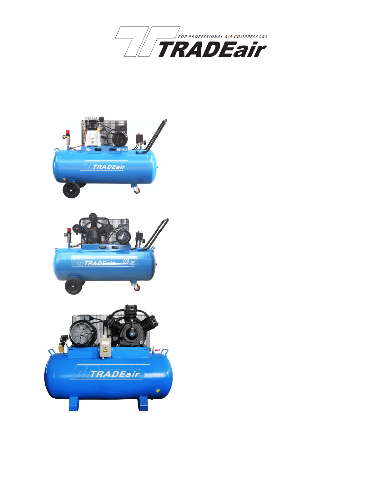
Belt Driven Air Compressors
INSTALLATION, MAINTENANCE AND OPERATION MANUAL
1,5kW to 15kW versions
ALUMINUM PUMP & SINGLE-PHASE RANGE
MCFRC230 2HP 050LT BELT DRIVE COMPRESSOR
MCFRC231 2HP 100LT BELT DRIVE COMPRESSOR
MCFRC232 3HP 100LT BELT DRIVE COMPRESSOR
MCFRC233 3HP 150LT BELT DRIVE COMPRESSOR
MCFRC234 3HP 200LT BELT DRIVE COMPRESSOR
W-TYPE CAST IRON PUMP & THREE-PHASE RANGE
PE50300 5.5HP 270LT BELT DRIVE COMPRESSOR
PE75300 7.5HP 270LT 2STAGE BELT DRIVE COMPRESSOR
PE100300 .10HP 270LT 2STAGE BELT DRIVE COMPRESSOR
PE100500 .10HP 500LT 2STAGE BELT DRIVE COMPRESSOR
PE150500 .15HP 500LT 2STAGE BELT DRIVE COMPRESSOR
W-TYPE CAST IRON PUMP & SINGLE-PHASE RANGE
MCFRC227 3HP 100LT BELT DRIVE COMPRESSOR
MCFRC228 3HP 150LT BELT DRIVE COMPRESSOR
MCFRC229 3HP 200LT BELT DRIVE COMPRESSOR

Thank you for purchasing your TRADEair air compressor. This manual will assist you in the correct and efficient
operation of your air compressor system. Please pay special attention to the safety guidelines and maintenance
procedures to ensure a long and dependable life for your equipment.
Every attempt has been made to ensure the completeness and correctness of this manual, but due to continued
research, development and improvement on our products certain aspects of thismanual may deviate from the actual
product supplied. The design of our products is subject to change without notice.
Our company is available to offer telephonic support in the event of any conflict occurring between this manual and
the actual product supplied. Enquiries may be made during office hours on the following telephone number;
+27 (0) 31 717 6800.
The manufacture of this compressor is in accordance with the strict standards which have passed ISO 9001
Certification. The pressure vessel is manufactured to EN286-1:1998 and complies with the South African
Occupational Health and Safety Act 85 of 1993 and all mandatory documentation is supplied with the compressor.
Production license:
Model of compressor:
Lot number of compressor:


SPECIFICATION TABLE
Model
MCFRC230
MCFRC231
MCFRC232
MCFRC233
MCFRC234
MCFRC227
MCFRC228
MCFRC229
Single Phase
Voltage
230V/50HZ
230V/50HZ
230V/50HZ
230V/50HZ
230V/50HZ
230V/50HZ
230V/50HZ
230V/50HZ
POWER
2.0HP
2.0HP
3.0HP
3.0HP
3.0HP
3.0HP
3.0HP
3.0HP
Tank capacity
50 L
100L
100 L
150 L
200 L
100 L
150 L
200 L
Motor speed
2850RPM
2850RPM
2850RPM
2850RPM
2850RPM
2850RPM
2850RPM
2850RPM
Pump Speed
1150RPM
1150RPM
950RPM
950RPM
950RPM
750RPM
750RPM
750RPM
Max Amperage
10A
10A
12A
12A
12A
12A
12A
12A
Air delivery
240 L/MIN
240 L/MIN
360 L/MIN
360 L/MIN
360 L/MIN
340 L/MIN
340 L/MIN
340 L/MIN
FAD at 7Bar
150 L/MIN
150 L/MIN
270 L/MIN
270 L/MIN
270 L/MIN
240 L/MIN
240 L/MIN
240 L/MIN
Max Pressure
0.8 Mpa
0.8 Mpa
0.8 Mpa
0.8 Mpa
0.8 Mpa
0.8 Mpa
0.8 Mpa
0.8 Mpa
Outlet
1PC X
Coupler
2PC X
Couplers
2PC X
Couplers
2PC X
Couplers
2PC X
Couplers
2PC X
Couplers
2PC X
Couplers
2PC X
Couplers
Packge size cm
93x38x73
105x42x86
105x42x86
131x45x96
136x50x103
105x42x86
131x45x96
136x50x103
G.W
60 KG
80 KG
85KG
110 KG
130 KG
95KG
120 KG
140 KG
Model
PE50300
PE75300 (2 Stages)
PE100300 (2 Stages)
PE100500 (2 Stages)
PE150500 (2 Stages)
Three Phase
voltage
380V/50HZ
380V/50HZ
380V/50HZ
380V/50HZ
380V/50HZ
POWER
5.5HP
7.5HP
10HP
10HP
15HP
Tank capacity
270 L
270 L
270 L
500 L
500 L
Motor speed
2850RPM
2850RPM
2850RPM
2850RPM
2850RPM
Pump Speed
850RPM
850RPM
850RPM
850RPM
850RPM
Max Amperage
8A
11A
15A
15A
22A
Air delivery
510 L/MIN
512 L/MIN
650 L/MIN
650 L/MIN
1470 L/MIN
FAD at 10.5 Bar
350 L/MIN@ 8Bar
400 L/MIN
500 L/MIN
500 L/MIN
1100 L/MIN
Max Pressure
0.8 Mpa
1.2 Mpa
1.2 Mpa
1.2 Mpa
1.2 Mpa
Outlet
2PC X Couplers
2PC X Couplers
2PC X Couplers
2PC X Couplers
2PC X Couplers
Packge size cm
161x54x115
161x54x115
161x54x115
178x64x133
182x77x145
G.W
220 KG
240 KG
250KG
350 KG
400 KG

1
Contents
Preface Page 1
Standard Warranty Page 2
Safety warning signs Page 4
Safety Tips Page 5
Preparations before use Page 8
Duty cycle Page 9
Operating the unit Page 9
Pressure regulation Page 11
Release of pressure Page 12
Pressure switch Page 13
Selection & connection of air driven tools Page 13
Maintenance Page 15
Preface
This manual describes the safety precautions, structure and functions of all systems and components, as well as the
operation and maintenance methods for the TRADEair air compressors.
The operators should read this manual carefully. Thorough understanding of all functions of systems and
components as well as safety precautions is necessary before operating or maintaining the compressor. If the user
fails to follow the operation and maintenance procedures contained in this manual, or dismantles and modifies the
machine in any way, or uses parts not specified and supplied by TRADEair then the warranty will be deemed to have
been compromised and no claims will be entertained.
There is no catalogue containing illustrations of parts and components in this manual. A separate parts manual is
supplied on request. Please quote the machine model and lot number when ordering parts to ensure correct supply
of parts.
This manual gives a general description of the operating procedures, required routine checks and other information
relating to the motor, electrical system and maintenance.

2
Standard Warranty
TRADEair compressors are covered by the following warranty relating to the manufacturing process and material
defects if the compressor is operated under conditions considered by us as normal operating conditions as is
detailed in this manual. Furthermore the warranty is subject to the compressor being maintained and serviced
according to the guidelines contained herein.
Compressor unit: within 14 months after the ex-factory date of delivery, or within 12 months after sale to the user,
the earlier shall prevail.
For the products not manufactured by TRADEair, the warranty clause of the original manufacturer shall be directly
applied in feasible conditions. Within the warranty period, TRADEair or its agent shall be informed in writing within
30 days of the defects being found, and the details shall be attached for identification, including the ex-factory serial
number, model, purchasing date and other relevant information.
The single responsibility assumed by TRADEair in this warranty is to repair or replace the component or parts which
are proven defective. TRADEair requires the return of defective components or parts for inspection.
Components or parts replaced during the warranty period will carry an additional 3 month warranty in cases where
their replacement takes place with less than 3 months remaining under the standard warranty.

3
TRADEair agrees to this extension of the warranty period on the condition that the compressor is operated under
conditions considered by us as normal operating conditions as is detailed in this manual and the compressor has
been maintained and serviced according to the guidelines contained herein.
TRADEair assumes no responsibility or obligation for the following;
A. Indirectly caused, incidental or special losses or damages.
B. Damages caused due to the normal wearing, abnormal operating conditions, neglects or wrong operation of
equipment, poor storage or transport damages.
C. Failing to follow the stipulations contained in the operation instructions, regulations or other special sales
conditions.
D. Labour and transportation costs, losses or damages caused due to incorrect operation of the compressor,
lack of maintenance or repairs performed by maintenance personnel not authorized by TRADEair.
E. Improper use of products.
This warranty is the sole warranty for the Purchaser for the TRADEair Compressor supplied with this
manual. No other warranty conditions exist unless expressly committed to by TRADEair COMPRESSORS
and reduced to writing and signed by a Director of:
L&G Tool & Machinery Distributors Limited,
6 Kyalami Road, Westmead,3610
P.O.Box 15313 Westmead 3608
Telephone: 031 –717 6800
Fax: 031 –717 6868

4
Safety Warning Signs
In this manual, the operations and items related to safety are identified according to the potential risk involved.
These are classified based on the severity of machine damages and the level of injuries that could be possibly
caused due to incorrect operation. These signs are represented and described in boldface with the following signs
respectively.
“Caution” describes unsafe factors which may cause general damages to the machines or injuries.
“Warning” describes unsafe factors which may cause property loss or injuries.
“Danger” describes unsafe factors of a mechanical nature which may cause severe accidents or injuries.
“Danger” describes unsafe factors of an electrical nature where the voltage exceeds a safe level and may
cause severe injuries.All electrical operations shall be performed by qualified electricians.
“Caution” describes unsafe factors which has hot surfaces and may cause property loss or injuries.
“Caution” draws your attention to important installation, operation and maintenance information.

5
Safety Tips
Please read the following information carefully before
operating and using the compressors
Warning
There are risks present in any air compressor and compressed air system!
If you fail to follow the operating procedures and safety precautions contained in this manual you are
exposing yourself and others to the possibility of accidents and injuries to yourself or damage to
equipment!
Before operating and maintaining the compressor, you must read carefully and understand this operating
manual!
These detailed instructions are given for the required safety precautions which shall be followed for the correct
operation of the compressor in conjunction with the risks stated in the Chapter ”Safety Rules”. Before delivering the
machine, clear warning labels have been attached to the places where risks are present and places requiring careful
operations. These labels may not be removed, covered or interfered with in any way.
1. Before any operation or maintenance is performed on the unit, you must read and understand the operation
manual.
2. It is not permitted to operate the unit above its rated air discharge capacity pressure.
3. Before the unit is delivered, individual protection controls have been calibrated and set correctly. Never modify
or remove the safety control components of the unit.
4. Never perform any maintenance procedures while the unit is operating as it contains pressurized coolants at
high thermal temperatures which have the ability to cause severe injuries.

6
5. Prior to any maintenances on the unit, the operator must confirm that:
⚫The unit is stopped;
⚫The internal pressure in the unit has been discharged;
⚫The power supply off and is correctly isolated.
6. Do not use flammable solutions to clean the compressor or its auxiliary equipment. Protection of electrical
components is necessary when using water based solutions to prevent ingress of water into electrical
enclosures of the unit.
7. In the event of the failure of a component it must be replaced immediately. Failure to do this may lead to
additional losses.
When determining where to set up the compressor in the shop, or when taking the air compressor to a job site, the
most important consideration is access to an adequate and properly fused power supply. Also, make sure the
compressor is not operating in an environment where there are any explosive, flammable or caustic fumes or gases.
A clear and well ventilated area is best for its safe operation. Place the compressor on a solid and level surface. Make
sure that the hoses you attach to your pneumatic device will be unrestricted in movement and not subject to being run
over by vehicles or punctured by any sharp objects in the area.
Since air compressors are often used for a sustained period of time, sometimes in restricted areas, it is also best to
wear ear protection to avoid long term exposure to the sound of the electric motor and compression pump.

7
If you find it necessary to use an extension cord with your compressor, make sure the cord is sufficiently rated for the
motor power. The extension cord must also contain an earthing wire. Never operate the compressor with a coiled
extension cable. Always repair or replace extension cords when they become worn or damaged.
Only trained and authorized personnel are allowed to operate the compressor. Prior to any operations, the
manual shall be carefully read and its contents shall be comprehensively understood.
Never allow the unit to start in an unsafe condition; if problems occur to the unit, do not attempt to restart the unit
until the fault has been corrected. The power supply shall be shut off and significant indication signs shall be
positioned to alert other personnel not to attempt to restart the unit.
Be aware that compressed air is hazardous. Only once all the compressed air is totally discharged in the
whole compressor system may maintenance and service be performed on the unit.
Routine daily service and maintenance schedules are to be adhered to. The unit shall be carefully inspected every
day to check for conditions such as leakage, loose, damaged and poorly adjusted parts, missing parts or
components. If any such items are discovered refrain from starting the unit and contact your dealer.

8
Preparations before first use
Before using your TRADEair Compressor, follow these steps:
1. Remove all packing materials and any protective plastic bags, zip-tie labels or tags from the compressor cylinder
head or oil plug.
2. Be sure the air filter is attached to the cylinder head.
3. Make sure the drain valve under the air tank is closed.
4. ADD OIL TO THE CRANKCASE. Oil has NOT been supplied in your air compressor. The oil level should be inthe
center of the oil sight gauge on the pump. Use proper compressor oil only. See figure 1 below.
Figure 1. Oil level indicator
NOTICE
The machine should never be run without the correct level of oil in the sump of the pump. The oil provides
lubrication to the cylinder rings which deliver the compressed air. Severe damage to the internal moving
parts can occur if there is not adequate oil flow. Check the oil level frequently, and change the oil on a
regular schedule.

9
Duty Cycle
The Air Compressor should not be operated on more than a 60% duty cycle. This means an air compressor that
pumps air for over 6 minutes in one tenminute period is considered misuse. This could mean that the air compressor
is undersized for the required air demand. The maximum compressor pump time per hour is 30 minutes.
“Caution” - Always be aware of the duty cycle for your air compressor. Failure to operate the air
compressor properly could result in overheating and motor seizure. There could also be risk of fire hazard
due to overheating. Be sure to use a compressor capable of handling the air demand.
Operating the unit
To start the air compressor:
1. Make sure the compressor switch is in the OFF position (knob with red cap above pressure gauges shown in
Figure 2 pressed down) before connecting the power supply.
Figure 2. ON/OFF button.
Check the pressure gauge to see that the tank pressure climbs to approximately ( 8 BAR for
MCFRC230/231/232/233/234/238/239/227/228/229 and PE50300; 12 BAR for PE75300, PE 100300, PE100500
and PE150500), then automatically turns off.
Note—If the compressor does not automatically switch off, flip the ON/OFF switch to OFF before pressure gets too
high. See the Pressure Regulator sub-section.

10
“Warning” Operating this equipment has the potential for flying debris to cause eye injury. Always
wear safety glasses or goggles when operating equipment. Everyday glasses or reading glasses only have
impact resistant lenses, they are not safety glasses. Be certain the safety glasses you wear meet the
appropriate standards.
1. Close the drain valve, shown in Figure 3, so the tank can build up pressure.
2. Double check the oil level to make sure it is at the proper height.
3. Connect the compressor to the power supply.
4. Pull the switch up to the ON position to start compressor.
Figure 3. Drain valve location.
Pressure Regulation

11
The tank pressure is displayed on the large tank pressure gauge, and the air to be delivered to the tool is displayed on
the regulator pressure gauge shown in Figure 4.
Figure 4. Pressure gauges
To control the air delivery to your tool: (optional accessories)
1. Adjust the air control knob, shown in Figure 5, to set the pressure that will be delivered to your tool. Turn the knob
clockwise to increase the pressure and counter-clockwise to decrease the pressure.
Figure 5. Air control knob.
Note—The air tool that you attach to the air compressor should have a preferred pressure operating level. Set the
pressure to be delivered to the tool according to this preferred level. Understand the duty cycle of the air
compressor that is described on page 9.
Release of Pressure

12
There are two ways to release air from thecompressor tankother than through your regulator and the use of air tools:
—The drain valve.
—The safety valve.
To release air by using the drain valve, simply turn the release nut to allow air to flow out of the tank. The drain valve
is shown in Figure 3. The drain valve is also used to drain condensation that builds up in the tank.
The safety valve automatically releases pressure if the tank reaches ( 8.8 BAR for
MCFRC230/231/232/233/234/238/239/227/228/229 and PE50300; 13.5 BAR for PE75300, PE 100300, PE100500
and PE150500).
To manually release the air in the tank by using the safety valve:
1. Locate the safety valve on the tank. The safety valve is shown below in Figure 6.
Figure 6. Safety valve.
2. Pull the metal ring on top of the safety valve to bleed pressure from the tank. Note—The ring is preset to release air
if the tank exceeds its maximum pressure of ( 8.8 BAR for MCFRC230/231/232/233/234/238/239/227/228/229 and
PE50300; 13.5 BAR for PE75300, PE 100300, PE100500 and PE150500).
DO NOT try to adjust the safety valve!
Pressure Switch

13
The pressure regulator has been factory set for the highest quality operating performance. The pressure regulator
adjusts the desired pressure range where the air compressor kicks in and out to keep the tank pressurized for the
best operating performance.
“Warning” Please refer your compressor to a qualified compressor technician for adjustments to the
pressure switch. Incorrect settings can be dangerous and/or overload the motor, causing damage, the possibility of
fire and loss to property.
Selection and connection of air driven tools
To connect air tools to your air compressor:
1. Make sure the compressor model you use has a sufficient volume in output for the air tool you plan to connect.
(Most air tools will have an air requirement stated in terms of a specific volume at a specific pressure.)
2. The compressor should put out a higher volume than the tool requires.
—If you are connecting multiple tools that will be used simultaneously, then the combined volume of each tool should
be added together and compared to the compressor output value.
3. Connect the tool, using a good quality air line with an adequate length to reach from the compressor to the point of
use.
Note—Quick-connect couplers, are a good option for fast and sure connection of tools and air hoses.

14
Make certain the air hose will not be placed in a position where it can become constricted or cut by a sharp object.
Note—Running over a hose with heavy vehicles may not cause an immediate leak, but it will shorten the life of the
hose. Consideration should also be given to the type of usage. A nailer or staple gun uses air in short bursts and it is
easier for the compressor to maintain pressure. A paint sprayer or grinder tends to use a more continuous stream of
air as these tools are run for longer time periods. It is always better to oversize a compressor to allow for variation in
the type of usage and the number of tools to be powered. Air tools being operated with insufficient air volume will not
perform their function satisfactorily
“Warning” Always disconnect air hose from tools whenever not in use or while servicing! During
maintenance, a tool connected to air may operate accidentally, causing serious personal injury!

15
Maintenance
Before Each Use
Regular periodic maintenance on your Air Compressor will ensure its optimum performance. Make a habit of
inspecting the following items before each time you use the air compressor.
Check the following items:
1. Check Oil Level! Use the sight gauge on the bottom of the crankcase to make sure the oil level is at the proper
height.
2. Drain the tanks of any condensation by opening the drain valve on the bottom of the tank. Note—Depending upon
the amount of use and the weather conditions, a certain amount of condensed water may be released.
For longevity of the compressor seals and the air tools you connect, it is best to keep the tank free of water. The tank
is best drained if the drain valve is opened when the system is slightly pressurized. Once water has stopped coming
out, you can close the drain valve.
3. Clean off cylinder head cooling fins of any dirt which might hamper air flow.
4. Check for worn or damaged cords and plugs.
5. Check for any other condition that could hamper the safe operation of the compressor.
“Caution” Please refer any maintenance of Vee-belts, pressure switches, electrical components and pump
to qualified compressor technicians.

16
After the first 10 hours of use
After the first 10 working hours or 30 days, whichever comes first, perform the following maintenance:
• Replace the oil in the pump with approved compressor oil (use ISO 100 viscosity, non detergent type, reciprocating
compressor oil).
• Make sure that all the fittings are tight and re-torque the cylinder head bolts according to the table below. If you are
unsure of this refer the unit to a qualified compressor technician.
• Remove the air filter foam element and rinse it out with water. Allow it to dry and re-install.
• Blow out any accumulated dirt between the cylinder cooling fins.
Torque ranges for tightening head bolts
Bolt Size
Min Torque
Max Torque
M8
22.45 Nm
27.43Nm
M10
45.28Nm
55.34Nm
M12
77.10Nm
94.23Nm
M14
123.00Nm
150.37Nm
Weekly
If the compressor is used on a daily basis, perform the following checks each week:
• Rinse the air filter foam element in water.
• Check for loose bolts or fittings.
This manual suits for next models
12
Table of contents
Other TRADEair Air Compressor manuals