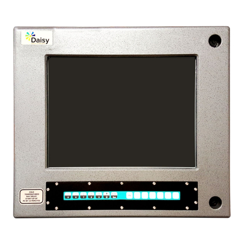
Spacelabs 91369 User manual

91369 Service Manual
070-1156-00 Rev. F

©2008 Spacelabs Medical, Inc.
All rights reserved. Contents of this publication may not be reproduced in any form without the written permission of
Spacelabs Medical. Products of Spacelabs Medical are covered by U.S. and foreign patents and/or pending patents.
Printed in U.S.A. Specifications and price change privileges are reserved.
Spacelabs Medical considers itself responsible for the effects on safety, reliability and performance of the equipment
only if:
• assembly operations, re-adjustments, modifications or repairs are carried out by persons authorized by
Spacelabs Medical, and
• the electrical installation of the relevant room complies with the requirements of the standard in force, and
• the equipment is used in accordance with the operations manual.
Spacelabs Medical will make available, on request, such circuit diagrams, component part lists, descriptions,
calibration instructions or other information which will assist appropriately qualified technical personnel to repair those
parts of the equipment which are classified by Spacelabs Medical as field repairable.
Spacelabs Medical is committed to providing comprehensive customer support beginning with your initial inquiry
through purchase, training, and service for the life of your Spacelabs Medical equipment.
CORPORATE OFFICES
U.S.A.
Spacelabs Medical, Inc.
5150 220th Ave SE
Issaquah, WA 98029
Telephone: 425-657-7200
Telephone: 800-522-7025
Fax: 425-657-7212
Authorized EC Representative UNITED KINGDOM
Spacelabs Healthcare, Ltd.
Beech House, Chiltern Court
Asheridge Road, Chesham
Buckinghamshire HP5 2PX
Telephone: 44 (0) 1494 784422
Fax: 44 (0) 1494 794414
BirthNet, Clinical Browser, Data Shuttle, Flexport, Intesys, Mermaid, MOM, Multiview, PCIS, PCMS, PrintMaster,
Quicknet, Sensorwatch, TRU-CAP, TRU-CUFF, TruLink, Ultralite, Ultraview, Ultraview Care Network, Ultraview Clinical
Messenger, Ultraview Digital Telemetry, Ultraview SL, Uni-Pouch, UCW, Varitrend and WinDNA are trademarks of
Spacelabs Medical, Inc.
Other brands and product names are trademarks of their respective owners.
Caution:
US Federal law restricts the devices documented herein to sale by, or on the order of, a
physician.
Before use, carefully read the instructions, including all warnings and cautions.
Rx Only
!

91369 Service Manual i
Contents Page
Table of Contents
Introduction
Overview. . . . . . . . . . . . . . . . . . . . . . . . . . . . . . . . . . . . . . . . . . . . . . . . . . . . . . . . . . . . . . . . . . . . . . . . . . . . . . . . . 1-1
Physical Dimensions. . . . . . . . . . . . . . . . . . . . . . . . . . . . . . . . . . . . . . . . . . . . . . . . . . . . . . . . . . . . . . . . . . . . . . . . 1-3
Electrical Specifications . . . . . . . . . . . . . . . . . . . . . . . . . . . . . . . . . . . . . . . . . . . . . . . . . . . . . . . . . . . . . . . . . . . . . 1-3
Environmental Requirements . . . . . . . . . . . . . . . . . . . . . . . . . . . . . . . . . . . . . . . . . . . . . . . . . . . . . . . . . . . . . . . . . 1-3
Regulatory Approvals . . . . . . . . . . . . . . . . . . . . . . . . . . . . . . . . . . . . . . . . . . . . . . . . . . . . . . . . . . . . . . . . . . . . . . . 1-3
Monitor Options . . . . . . . . . . . . . . . . . . . . . . . . . . . . . . . . . . . . . . . . . . . . . . . . . . . . . . . . . . . . . . . . . . . . . . . . . . . 1-4
Display . . . . . . . . . . . . . . . . . . . . . . . . . . . . . . . . . . . . . . . . . . . . . . . . . . . . . . . . . . . . . . . . . . . . . . . . . . . . . . . . . . 1-4
Setup
Unpacking the Monitor . . . . . . . . . . . . . . . . . . . . . . . . . . . . . . . . . . . . . . . . . . . . . . . . . . . . . . . . . . . . . . . . . . . . . . 2-1
Assembling the Monitor . . . . . . . . . . . . . . . . . . . . . . . . . . . . . . . . . . . . . . . . . . . . . . . . . . . . . . . . . . . . . . . . . . . . . 2-2
Connections . . . . . . . . . . . . . . . . . . . . . . . . . . . . . . . . . . . . . . . . . . . . . . . . . . . . . . . . . . . . . . . . . . . . . . . . . . . . . . 2-4
Cabling . . . . . . . . . . . . . . . . . . . . . . . . . . . . . . . . . . . . . . . . . . . . . . . . . . . . . . . . . . . . . . . . . . . . . . . . . . . . . . . . . . 2-7
SDLC Bus Termination. . . . . . . . . . . . . . . . . . . . . . . . . . . . . . . . . . . . . . . . . . . . . . . . . . . . . . . . . . . . . . . . . . . . . . 2-8
Network Installation . . . . . . . . . . . . . . . . . . . . . . . . . . . . . . . . . . . . . . . . . . . . . . . . . . . . . . . . . . . . . . . . . . . . . . . 2-11
Power-ON Test. . . . . . . . . . . . . . . . . . . . . . . . . . . . . . . . . . . . . . . . . . . . . . . . . . . . . . . . . . . . . . . . . . . . . . . . . . . 2-12
Configuring the Monitor . . . . . . . . . . . . . . . . . . . . . . . . . . . . . . . . . . . . . . . . . . . . . . . . . . . . . . . . . . . . . . . . . . . . 2-13
Theory
Overview. . . . . . . . . . . . . . . . . . . . . . . . . . . . . . . . . . . . . . . . . . . . . . . . . . . . . . . . . . . . . . . . . . . . . . . . . . . . . . . . . 3-1
Major System Components . . . . . . . . . . . . . . . . . . . . . . . . . . . . . . . . . . . . . . . . . . . . . . . . . . . . . . . . . . . . . . . . . . 3-2
Printed Circuit Board Assemblies (PCBAs) . . . . . . . . . . . . . . . . . . . . . . . . . . . . . . . . . . . . . . . . . . . . . . . . . . . . . . 3-5
Interconnect and Connector PCBAs. . . . . . . . . . . . . . . . . . . . . . . . . . . . . . . . . . . . . . . . . . . . . . . . . . . . . . . . . . . 3-15
Bezel Assembly . . . . . . . . . . . . . . . . . . . . . . . . . . . . . . . . . . . . . . . . . . . . . . . . . . . . . . . . . . . . . . . . . . . . . . . . . . 3-16
Boot Sequence Overview . . . . . . . . . . . . . . . . . . . . . . . . . . . . . . . . . . . . . . . . . . . . . . . . . . . . . . . . . . . . . . . . . . . 3-18
Normal Operation Overview . . . . . . . . . . . . . . . . . . . . . . . . . . . . . . . . . . . . . . . . . . . . . . . . . . . . . . . . . . . . . . . . . 3-18
Display . . . . . . . . . . . . . . . . . . . . . . . . . . . . . . . . . . . . . . . . . . . . . . . . . . . . . . . . . . . . . . . . . . . . . . . . . . . . . . . . . 3-19
Parameter Modules . . . . . . . . . . . . . . . . . . . . . . . . . . . . . . . . . . . . . . . . . . . . . . . . . . . . . . . . . . . . . . . . . . . . . . . 3-21
CPU PCBA Connectors . . . . . . . . . . . . . . . . . . . . . . . . . . . . . . . . . . . . . . . . . . . . . . . . . . . . . . . . . . . . . . . . . . . . 3-21
CPU PCBA Jumpers. . . . . . . . . . . . . . . . . . . . . . . . . . . . . . . . . . . . . . . . . . . . . . . . . . . . . . . . . . . . . . . . . . . . . . . 3-22
I/O PCBA Connectors . . . . . . . . . . . . . . . . . . . . . . . . . . . . . . . . . . . . . . . . . . . . . . . . . . . . . . . . . . . . . . . . . . . . . 3-22
Interconnect PCBA Connectors . . . . . . . . . . . . . . . . . . . . . . . . . . . . . . . . . . . . . . . . . . . . . . . . . . . . . . . . . . . . . . 3-23
Maintenance
Overview. . . . . . . . . . . . . . . . . . . . . . . . . . . . . . . . . . . . . . . . . . . . . . . . . . . . . . . . . . . . . . . . . . . . . . . . . . . . . . . . . 4-1
Mechanical Inspection . . . . . . . . . . . . . . . . . . . . . . . . . . . . . . . . . . . . . . . . . . . . . . . . . . . . . . . . . . . . . . . . . . . . . . 4-2
Electrical Safety Testing . . . . . . . . . . . . . . . . . . . . . . . . . . . . . . . . . . . . . . . . . . . . . . . . . . . . . . . . . . . . . . . . . . . . . 4-2
Preventive Maintenance . . . . . . . . . . . . . . . . . . . . . . . . . . . . . . . . . . . . . . . . . . . . . . . . . . . . . . . . . . . . . . . . . . . . . 4-4
Functional Tests . . . . . . . . . . . . . . . . . . . . . . . . . . . . . . . . . . . . . . . . . . . . . . . . . . . . . . . . . . . . . . . . . . . . . . . . . . . 4-5
Assembly/Disassembly Procedures . . . . . . . . . . . . . . . . . . . . . . . . . . . . . . . . . . . . . . . . . . . . . . . . . . . . . . . . . . . . 4-6
Cleaning . . . . . . . . . . . . . . . . . . . . . . . . . . . . . . . . . . . . . . . . . . . . . . . . . . . . . . . . . . . . . . . . . . . . . . . . . . . . . . . . 4-24
Troubleshooting
Overview. . . . . . . . . . . . . . . . . . . . . . . . . . . . . . . . . . . . . . . . . . . . . . . . . . . . . . . . . . . . . . . . . . . . . . . . . . . . . . . . . 5-1
System Startup . . . . . . . . . . . . . . . . . . . . . . . . . . . . . . . . . . . . . . . . . . . . . . . . . . . . . . . . . . . . . . . . . . . . . . . . . . . . 5-2
Boot Menu . . . . . . . . . . . . . . . . . . . . . . . . . . . . . . . . . . . . . . . . . . . . . . . . . . . . . . . . . . . . . . . . . . . . . . . . . . . . . . . 5-3
Power-ON Diagnostics . . . . . . . . . . . . . . . . . . . . . . . . . . . . . . . . . . . . . . . . . . . . . . . . . . . . . . . . . . . . . . . . . . . . . . 5-6
Extended Diagnostics . . . . . . . . . . . . . . . . . . . . . . . . . . . . . . . . . . . . . . . . . . . . . . . . . . . . . . . . . . . . . . . . . . . . . . . 5-6
Diagnostic Menus . . . . . . . . . . . . . . . . . . . . . . . . . . . . . . . . . . . . . . . . . . . . . . . . . . . . . . . . . . . . . . . . . . . . . . . . . . 5-7

91369 Service Manual ii
Table of Contents
Error Log. . . . . . . . . . . . . . . . . . . . . . . . . . . . . . . . . . . . . . . . . . . . . . . . . . . . . . . . . . . . . . . . . . . . . . . . . . . . . . . . 5-10
Diagnostics Failure Messages and Error Codes . . . . . . . . . . . . . . . . . . . . . . . . . . . . . . . . . . . . . . . . . . . . . . . . . 5-11
System Troubleshooting . . . . . . . . . . . . . . . . . . . . . . . . . . . . . . . . . . . . . . . . . . . . . . . . . . . . . . . . . . . . . . . . . . . . 5-13
Parts
Overview. . . . . . . . . . . . . . . . . . . . . . . . . . . . . . . . . . . . . . . . . . . . . . . . . . . . . . . . . . . . . . . . . . . . . . . . . . . . . . . . . 6-1
Parts List. . . . . . . . . . . . . . . . . . . . . . . . . . . . . . . . . . . . . . . . . . . . . . . . . . . . . . . . . . . . . . . . . . . . . . . . . . . . . . . . . 6-1
Assembly Drawings and Schematics . . . . . . . . . . . . . . . . . . . . . . . . . . . . . . . . . . . . . . . . . . . . . . . . . . . . . . . . . . . 6-4
Directory of Keys
BIOMED Directory of Keys . . . . . . . . . . . . . . . . . . . . . . . . . . . . . . . . . . . . . . . . . . . . . . . . . . . . . . . . . . . . . . . . . . . 7-1
Glossary
Appendix A — Electromagnetic Compatibility
Electromagnetic Emissions. . . . . . . . . . . . . . . . . . . . . . . . . . . . . . . . . . . . . . . . . . . . . . . . . . . . . . . . . . . . . . . . . . . A-1
Electromagnetic Immunity . . . . . . . . . . . . . . . . . . . . . . . . . . . . . . . . . . . . . . . . . . . . . . . . . . . . . . . . . . . . . . . . . . . A-2
Separation Distances . . . . . . . . . . . . . . . . . . . . . . . . . . . . . . . . . . . . . . . . . . . . . . . . . . . . . . . . . . . . . . . . . . . . . . . A-3
Appendix B — Symbols

91369 Service Manual 1-1
Contents
Introduction
Overview. . . . . . . . . . . . . . . . . . . . . . . . . . . . . . . . . . . . . . . . . . . . . . . . . . . . . . . . . . . . . . . . . . . . . . . . . . . . . . .1
Physical Dimensions. . . . . . . . . . . . . . . . . . . . . . . . . . . . . . . . . . . . . . . . . . . . . . . . . . . . . . . . . . . . . . . . . . . . . .3
Electrical Specifications . . . . . . . . . . . . . . . . . . . . . . . . . . . . . . . . . . . . . . . . . . . . . . . . . . . . . . . . . . . . . . . . . . .3
Environmental Requirements . . . . . . . . . . . . . . . . . . . . . . . . . . . . . . . . . . . . . . . . . . . . . . . . . . . . . . . . . . . . . . .3
Regulatory Approvals . . . . . . . . . . . . . . . . . . . . . . . . . . . . . . . . . . . . . . . . . . . . . . . . . . . . . . . . . . . . . . . . . . . . .3
Monitor Options . . . . . . . . . . . . . . . . . . . . . . . . . . . . . . . . . . . . . . . . . . . . . . . . . . . . . . . . . . . . . . . . . . . . . . . . .4
Overview
Spacelabs Healthcare’s products are designed and manufactured under good manufacturing practices and in
compliance with all applicable regulatory requirements. To ensure proper operation in accordance with these
guidelines, this product must be maintained by trained technicians, using Spacelabs Healthcare authorized
replacement parts.
Warnings, cautions, and notes are used throughout this manual. They are identified by the formats shown
below. Be sure to read all warnings, cautions, and notes included in each section of this manual.
Warning:
Alerts the user to potentially serious outcomes (death, injury, or serious adverse events) to the
patient or user.
Caution:
Alerts the user to actions to be taken to avoid non-serious injury to the patient or user, or to
adverse effects to the device.
Note:
Failure to observe notifications may result in unexpected outcomes.
The 91369 monitor is a lightweight, portable monitor designed for use as a compact bedside monitor or as a
battery-operated transport monitor. The monitor features a five-wire, resistive touchscreen and can be
operated on either AC mains or battery power.
The single-high module slot on the right side of the monitor accepts all single-high modules, including the
90496 Ultraview®Command module and 91496 Ultraview SL™Command module, to permit the monitoring of
parameters such as electrocardiography (ECG), pulse oximetry (SpO2), temperature, and invasive pressure.

Introduction
91369 Service Manual 1-2
Figure 1-1: 91369 monitor
Figure 1-2: 91369-Y Neonatal intensive care unit (NICU) monitor

91369 Service Manual 1-3
Introduction
Physical Dimensions
Electrical Specifications
Designed for continuous operation. Requires outlet with ground (Protective Earth) conductor. Designated
Class I by applicable electrical safety standards.
AC Line Requirements
Environmental Requirements
Regulatory Approvals
CSA certified. Meets IEC60601-1, UL60601-1, and CSA C22.2 No. 601.1 for electrical safety. CE marked in
accordance with the Medical Device Directive 93/42/EEC.
Assembled weight 10.0 pounds (4.6 kg)
Dimensions 8.3 (H) × 11.7 (W) × 6.2 (D) inches
(21.1 × 29.7 × 15.8 cm)
AC input voltage range 100 to 240 VAC
AC input current 1.0 A
AC input frequency range 50 – 60 Hz
Operating temperature 0° to 50° C
Humidity (operating) 10% to 95% relative humidity, non-condensing
®
C
US
®
C
US
C
0123

Introduction
91369 Service Manual 1-4
Monitor Options
The following options are available:
Display
The video input of the display conforms with the Video Electronics Standards Association (VESA) display
resolution of 1024 × 768 pixels. The monitor does not support an external touchscreen.
Table 1: 91369 Monitor Options
Option Definition
DPerioperative
JDual-channel internal recorder (Polish,Czech, Portuguese
language support only)
NVital Signs Calculations
ODrug Dose Calculations
QData Shuttle®
RPatient Data Logger (PDL)
UDual-channel internal recorder (no Polish language support)
YNeonatal intensive care unit monitor
ZWireless networking
04 Four waveform zones
06 Six waveform zones
Vertical Horizontal
Rate 64 Hz 51.584 Hz
Front porch 58 μs 0.350 μs
Sync width 116 μs 1.985 μs
Back porch 562 μs 2.101 μs
Blank 737 μs 4.435 μs
Video clock rate 68.5 MHz 51.584 KHz

91369 Service Manual 2-1
Contents
Setup
Unpacking the Monitor . . . . . . . . . . . . . . . . . . . . . . . . . . . . . . . . . . . . . . . . . . . . . . . . . . . . . . . . . . . . . . . . . . . .1
Assembling the Monitor . . . . . . . . . . . . . . . . . . . . . . . . . . . . . . . . . . . . . . . . . . . . . . . . . . . . . . . . . . . . . . . . . . .2
Connections . . . . . . . . . . . . . . . . . . . . . . . . . . . . . . . . . . . . . . . . . . . . . . . . . . . . . . . . . . . . . . . . . . . . . . . . . . . .4
Cabling . . . . . . . . . . . . . . . . . . . . . . . . . . . . . . . . . . . . . . . . . . . . . . . . . . . . . . . . . . . . . . . . . . . . . . . . . . . . . . . .7
Network Installation . . . . . . . . . . . . . . . . . . . . . . . . . . . . . . . . . . . . . . . . . . . . . . . . . . . . . . . . . . . . . . . . . . . . .11
Power-ON Test . . . . . . . . . . . . . . . . . . . . . . . . . . . . . . . . . . . . . . . . . . . . . . . . . . . . . . . . . . . . . . . . . . . . . . . . .12
Configuring the Monitor . . . . . . . . . . . . . . . . . . . . . . . . . . . . . . . . . . . . . . . . . . . . . . . . . . . . . . . . . . . . . . . . . .13
Unpacking the Monitor
The 91369 monitor, one or two batteries, external AC power supply, and any optional accessories are all
packaged and shipped in a single box. Keep at least one shipping box and its packing materials for re-
shipping, if the monitor should ever require factory service.
Caution:
Observe precautions for handling electrostatic-sensitive devices!
Note:
• Never touch electrostatic-sensitive electronic components without following proper anti-static
procedures, including the use of an ESD wrist band and mat. An electrostatic discharge from your
fingers can permanently damage electronic components and cause latent failures.
• All static-sensitive electronic components are packaged in static-shielding bags. Retain the bag for
repackaging the component should you need to store it or return it to Spacelabs Healthcare for any
reason.
The monitor is typically shipped as follows:
Top Assembly — Contains the main enclosure with installed CPU, power supply, and I/O PCBAs.
Accessories — Contains the external DC power supply, U.S. power cord, international power cords (if
applicable), and any cable assemblies ordered.
Before installing the monitor:
Note:
When removing items from the shipping containers, ensure that you remove ALL components from each
container.
1 Unpack the received equipment.
2 Unpack the mounting hardware.
3 Conduct an equipment audit.

Setup
91369 Service Manual 2-2
Upon receiving the equipment, complete a detailed inventory to verify that the equipment you received
matches your order. This inventory must include serial numbers, model numbers, and all options and cables
received. Carefully inspect these items for shipping damage. If any damage is evident, immediately notify the
freight company and Spacelabs Healthcare.
Assembling the Monitor
Power and Battery Status
The three LEDs on the monitor indicate whether the monitor is connected to the AC mains power and the
status of any installed batteries. Battery status conditions are indicated as described in the following sections.
Figure 2-1: Battery status information
Power LED
The power LED is located immediately to the right of the power ON/OFF switch. This LED is lit whenever the
monitor is connected to AC mains power via its power supply, and is not lit if the monitor is not connected to
the AC mains power.
Battery Status LEDs
These LEDs are only active while the unit is connected to AC mains power.
Unlit LED
A battery LED that is neither solid ON nor flashing indicates a battery is not present.
Solid Green LED
A solid green battery LED indicates that the battery is fully charged. Only a charging cycle or a faulty battery
will cause the green LED to flash, and these conditions only occur when a battery is installed in the monitor.
INSERT GRAPHIC HERE
Power LED Battery status
LEDs
Power ON/OFF
switch

91369 Service Manual 2-3
Setup
Flashing Green LED — Battery Charging
A flashing green battery LED indicates an installed battery is being charged and the monitor is not completely
ready to be used in transport mode. This LED flashes in a constant pattern with no delays with the monitor
powered ON or OFF. The flashing is different than the battery fault detection flash.
Note:
The green LED stops flashing and stays ON when the charging cycle is complete.
Intermittent Flashing Green LED — Battery Fault Detected
An intermittent flashing green LED indicates that this battery will not hold a charge, or is taking too long to
charge. The intermittent signal is a repeating pattern of a solid green LED for one second and a flashing LED
for one second. An error message is also added to the error log for review by your system administrator.
To determine whether a battery is faulty, power the monitor ON using the front-panel switch and observe the
message displayed along the bottom of the monitor screen. Replace a faulty battery with the same battery
type.
Installing/Replacing Batteries
NiMH batteries are used in the monitor. Refer to Figure 2-2 to install one or two batteries.
Figure 2-2: Monitor battery installation

Setup
91369 Service Manual 2-4
While the monitor is operational, a single battery can be exchanged under any of the following conditions
without a loss of patient data:
• The monitor is being powered by the external power supply.
• The monitor is operating on two batteries, and one charged battery remains connected at all times during
the exchange.
Warning:
Batteries exposed to short circuit, high temperature, or fire may leak, vent, or explode.
Caution:
Follow the manufacturer’s recommended handling procedure. Collect and transport batteries in a
manner that prevents short circuit, compacting, mutilation, or any other abuse that would
compromise the physical integrity.
Connections
Refer to Figure 2-3 for available connections on the monitor’s rear panel. Refer to Figure 2-4 for available
connections on the monitor’s side panel.
Rear Panel
Figure 2-3: Rear panel connections
Equipotential ground post
External power supply input
SDLC port
Alarm relay output
Video output
Serial port

91369 Service Manual 2-5
Setup
Caution:
For continued electromagnetic interference (EMI) radiation compliance, use only cables that have
been tested and approved by Spacelabs Healthcare. Refer to Table 2 on page 6-3 for all cable part
numbers.
Table 1: Rear Panel Cables
Rear Panel
Connection Description Part Number
Cable, Serial I/O (RS-232) As required
Cable, Video, DB15HD Male to DB15HD Male,
1.8 m (6 feet) 012-0593-00
Cable, SDLC As required
Cable, Monitor to Module Housing, 0.61 m (2 feet) 012-0532-02
Cable, Monitor to Module Housing, 1.22 m (4 feet) 012-0532-04
Cable, Monitor to Module Housing, 2.44 m (8 feet) 012-0532-08
Cable, Monitor to Module Housing, 3.05 m (10 feet) 012-0532-10

Setup
91369 Service Manual 2-6
Side Panel
Figure 2-4: Side panel connections
Note:
The USB ports are to be used for Spacelabs-approved devices only (Symbol/Metrologic barcode scanner
and Microsoft USB keyboard/mouse devices).
Table 2: Side Panel Cables
Side Panel
Connection Description Part Number
Cable, Ethernet, 10/100BaseT, 0.94 m (3 feet) 175-0951-00
Cable, Ethernet, 10/100BaseT, 1.8 m (6 feet) 175-0951-01
Cable, Ethernet, 10/100BaseT, 3.7 m (12 feet) 175-0951-02
Cable, Ethernet, 10/100BaseT, 6.1 m (20 feet) 175-0951-03
USB ports
10/100BaseT network
connection

91369 Service Manual 2-7
Setup
Cabling
Maximum Cable Lengths
The following cables are limited to the indicated maximum length:
•SDLC Cable — 12.2 m (40 feet) maximum (total length from the monitor to the last device on the bus). For
longer SDLC cable runs, contact a Spacelabs Healthcare Field Service Engineer.
•Video Cable — 30.5 m (100 feet) maximum (total length from the monitor to the last display).
•Ethernet cable (10/100BaseT) — 100 m (328 feet) maximum.
SDLC External Devices
External devices (for example, Flexport®system interfaces) can be connected to the SDLC bus. (In this
context, the term “external” means connected to the SDLC bus by cable via an external connector. This is in
contrast to modules, which are connected by inserting them into a module housing.)
If no supplementary module housings are present (in addition to the module slot integral to the monitor itself),
then external devices are connected directly to the SDLC connector of the monitor.
If one or more supplementary module housings are present, Flexport devices are connected to connector J2
on one of the 90499 or 90491 supplementary module housings, or J3 on model 90485. Refer to the Module
Housings and Power Supplies Service Manual (P/N 070-0680-xx).
If multiple module housings are present, external devices must be connected to the last module housing in the
daisy-chain; that is, the housing electrically farthest from the monitor on the SDLC bus. Even though multiple
connectors may be available, only the SDLC connector on the most distal module housing can be used for
connecting external devices. Do not use more than a single Flexport connector, regardless of how many
module housings are present.
If multiple Flexport interfaces are to be installed, they must be daisy-chained using the T-cable supplied with
those devices. Up to three Flexport interfaces may be connected in this way.
Warning:
Unreliable system operation will occur if the SDLC bus is not correctly terminated or the maximum
cable length is exceeded. Flexport interfaces must be attached to the most distal module housing
on the SDLC bus.
SDLC Cable Interconnection
To ensure electromagnetic interference (EMI) compliance, the appropriate Spacelabs Healthcare
9-pin connector must be used. Refer to the Module Housings and Power Supplies Service Manual
(P/N 070-0680-xx).

Setup
91369 Service Manual 2-8
SDLC Bus Termination
The SDLC bus must be properly terminated for correct operation. If no external devices (for example, Flexports
or multigas analyzers) are connected, proper termination of the SDLC bus is accomplished automatically. If
external devices are connected, the switch on the module housing farthest from the monitor must be set to the
terminated ( ) position. All others must be set to the non-terminated ( ) position. The SDLC clock and
data signals are switched by the terminator switches and are not present “downstream” of any switch set to the
position.
Figure 2-5: Terminator switch settings
Because bus termination is handled by setting the switches appropriately, an external terminator is only
required when external devices are connected.
If external devices are connected, an external cable terminator is required to terminate the SDLC bus. This
must be installed at the end of the SDLC bus (following the last external device). In this case, all module
housings must have their switches in the position.
Note:
Flexports require a powered Flexport cable (P/N 012-0555-00) when used with the 90491/90499 module
housing or 91369 monitor. SDLC data is only passed along to the external device(s) when the terminator
switch (SW2) is in the position.
Alarm Relay
Alarm output signals are available at the Nurse Alert ( ) connector instantaneously when an alarm occurs.
Table 3 describes the connector pinouts for remote alarms. Figure 2-6, Figure 2-7, and Figure 2-8 illustrate the
circuits for each alarm function.
External Alarm Pinout
Alarm connector pinouts are as follows:
Table 3: Connector Pinouts
Pin Alarm Circuit Meaning
1
Alarm 0 (high priority)
Common
2 Normally Closed
3 Normally Open
4GND
Non-terminated Terminated

91369 Service Manual 2-9
Setup
Warning:
For operational safety and reliability, the following relay contact ratings MUST NOT BE
EXCEEDED:
• Current = 250 ma
• Voltage = 28 V AC/DC
Figure 2-6: Alarm 0 (high priority) relay schematic
5
Alarm 1 (medium priority)
Normally Closed
6 Normally Open
7 Common
8GND
9 +12 V, 140 mA
10 GND
11 GND
12
Alarm 2 (low priority)
Normally Open
13 Common
14 Normally Closed
Table 3: Connector Pinouts (continued)
Pin Alarm Circuit Meaning
ALMON
+12 V
+5 V
relay
1
2
3
4
8
10
9
common
NC
NO
140 mA
Relay maximum ratings:
28 V AC/DC
0.25 A
11
GND
GND
GND
GND

Setup
91369 Service Manual 2-10
Figure 2-7: Alarm 1 (medium priority) relay schematic
Figure 2-8: Alarm 2 (low priority) relay schematic
ALMON
+12 V
+5 V
relay
7
5
6
4
8
10
9
common
NC
NO
140 mA
Relay maximum ratings:
28 V AC/DC
0.25 A
11
GND
GND
GND
GND
ALMON
+12 V
+5 V
relay
13
14
12
4
8
10
9
common
NC
NO
140 mA
Relay maximum ratings:
28 V AC/DC
0.25 A
11
GND
GND
GND
GND

91369 Service Manual 2-11
Setup
Network Installation
A typical network consists of bedside and central monitors and an optional clinical information system
(Figure 2-9).
Figure 2-9: Typical network configuration
Warning:
Ensure that the Ethernet wall plate and the shield of the Ethernet connecting cable are bonded to
the hospital grounding system.
Ethernet Network Connection
Caution:
• Only qualified personnel should attempt to connect a monitor to an Ethernet LAN the first time.
• Do not connect the monitor to an Ethernet local area network (LAN) prior to configuring the
following settings. The monitor must be properly configured for LAN access before you operate
the monitor. If you fail to correctly configure the monitor, you may interrupt other units also
using the LAN.
Note:
Detailed installation instructions for the physical Ethernet LAN are beyond the scope of this document.
91387-27
Bedside #n
91369
Bedside #n
Clinical
Information
System
91387-38
Central #n
M
o
d
u
l
e
s
Module
Ethernet Network
94263
Flat-panel display
94260-19
Flat-panel display

Setup
91369 Service Manual 2-12
To connect a monitor onto an existing Spacelabs Healthcare Ethernet LAN, complete the following
steps:
1 Install the monitor on a suitable table or shelf, ensuring that the air flow to the side air intake vents is
unobstructed, or use a Spacelabs Healthcare mounting option.
2 Ensure that the monitor is not connected to the LAN.
3 Plug the power cord attached to the monitor’s DC power supply into a standard hospital-grade AC power
supply.
4 Power ON the monitor.
5 Enter a unique MONITOR ID, BED NAME, and SUBNET for the monitor. Refer to Network Setup on page 2-
13 for more information.
6 Attach the 10/100BaseT LAN transceiver cable into the RJ45 connector on the left side of the monitor
(in Figure 2-4 on page 2-6).
7 Connect the other end of the Ethernet cable from the monitor to the nearest port.
8 Configure the monitor’s other network settings as necessary to ensure proper communication on the
network. Refer to Network Setup on page 2-13.
Ethernet Network Disconnection
To remove a monitor from the LAN, disconnect the network cable from the 10/100BaseT network connection
(in Figure 2-4 on page 2-6).
Power-ON Test
Each time the monitor is powered ON:
• Diagnostic information displays for approximately 10 seconds.
• The embedded alarm light cycles red and yellow. Some models may cycle red, yellow, and cyan.
• Monitor keys display on the right side of the screen.
The monitor is now ready for normal operation.
External Devices
If an external SDLC device, such as a Flexport interface, is to be installed, the 9-pin SDLC connector on the
rear of the monitor or the module housing must be used. If multiple SDLC ports on module housings are
available, only the SDLC port on the module housing farthest from the monitor can be used for external
devices. Set the termination switch to non-terminated ( ) for all module housings and then terminate the
external device.
Table of contents
