SPAL SHAVED-B User manual

Æ
Installation Manual &
Operation Instructions
Shaved-B
Limited Warranty Statement
SPAL USA WARRANTY STATEMENT
SPAL USA warrants this product to be free from defects in material and workmanship for a
period of one (1) year from the date of sale to the original purchaser, and not more than two (2)
years from the date of manufacture. SPAL USA will repair this product free of charge if, in the
judgment of SPAL USA, it has been proven defective within the warranty period. The product
should be returned, at the customer expense, to the location of original purchase. This warranty
does not cover any expenses incurred in the removal and/or reinstallation of the product.This
warranty does not apply to any product damaged by improper installation, accidental misuse,
abuse, improper line voltage, fire, flood, lightning, or other acts of God, or a product altered or
repaired by anyone other than SPAL USA.This warranty is in lieu of other warranties, expressed
or implied, including any implied warranty of merchantability. No person is authorized to assume
for SPAL USA any other liability concerning the sale of this product.
IMPORTANT-KEEP YOUR INVOICE WITH THIS WARRANTY STATEMENT!
10/04
8
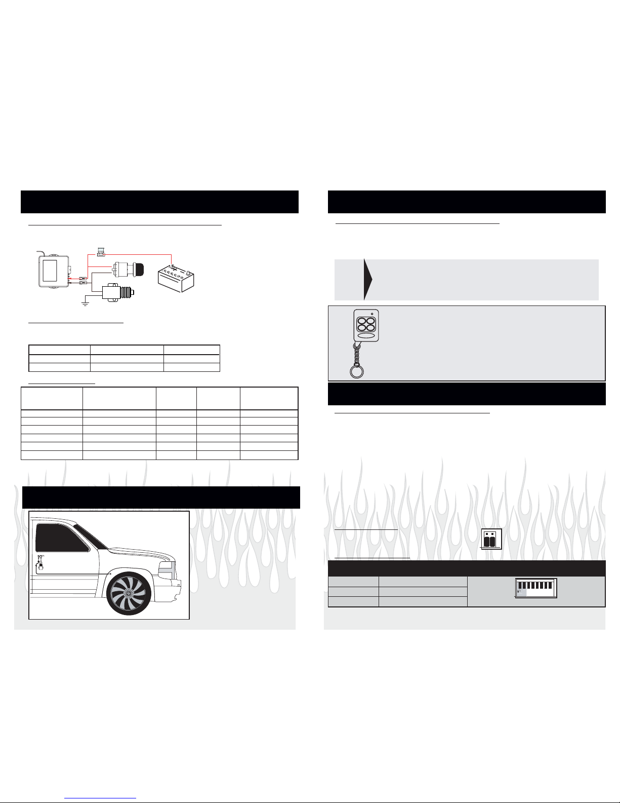
Trouble Shooting Reverse Polarity Wiring Problems
Switch doesn't work properly but the shaved kit transmitters do work
Step 1 Did you purchase a switch kit designed for three switches and only use two switches?
YES - Connect third switch
NO - Check wiring
Switch works properly but shaved kit transmitters do not work
Step 1 Does the LED on the remote light up when you press the transmitter button?
YES - Transmitter works properly continue to step 2
NO - Replace transmitter battery
Step 2 Can you hear the receiver make a clicking sound when you press channel 1 or 2 on
the transmitter?
YES - Receiver and relay work properly. Go to step 4
NO - Go to step 3
Step 3 Does the LED on the receiver light up when the transmitter button is pressed?
YES - Transmitter is properly learned and OK, go to Step 4
NO - Check power and ground to the receiver and then reprogram the transmitters
Step 4 Use a test light to check for voltage at pin 87 of the relay. Did the test show greater
than 10 volts?
YES - The relay checked works properly. The other side of the motor is not properly grounded.
NO - Connect pin 87 to a proper voltage source.
SPAL USA, 512 Tuttle Street, Des Moines, IA 50309-4618
[email protected], www.spal-usa.com
Main/Sales: 800-345-0327, Sales: 888-SPAL-USA
Tech Support Line: 800-454-7725

Each Kit Contains The Following Components
B
Y
R
TT
AE
Output From Receiver 87A
86 85
30
87
+ 12 VDC
FUSE
30
87A
87
85
86
Output From Receiver
Power Window
Motor
S
W
I
T
C
H
Y
T
BATER
85
86
30
87
Output From Receiver 87A
+ 12 VDC Output
+ 12 VDC
FUSE
Optional Wiring Diagrams
Positive Output
Negative Output
Reverse Polarity Output
T
BATY
ER
Output From Receiver
86
Ground Output
30
87A
87
85
GROUND
FUSE
+ 12 VDC
FOR POWER WINDOWS TWO RELAYS MUST BE PLACED BETWEEN THE SWITCH AND THE
WINDOW MOTOR. THE DASHED LINES INDICATE WHERE THE WIRES MUST BE CUT.
(1) Receiver (2) Remotes
(2) Wire Harnesses
Installation Instructions for SPAL Shaved Door Handle Kit
Shaved-40
This kit is designed to operate up to seven functions via the four-button remote control.
Channels 1 and 2 are Positive outputs used to open your drivers and passenger doors. Channels 3
through 7 are all negative outputs tht can be used ot operate power door locks, power door releases, truck
releases, control linear actuators, or roll power windows up or down, with an additional (external) relay.
(See Page 7)
**Proper wiring is critical to the correct operation of this product. Inspect all wiring to be certain of proper
connections, a quality ground, and appropriate fusing. Also check wire rounting, keeping wires away from
potential damage such as moving parts**
2 7

• The solenoids provided in the SHAVED40 kit can be mounted horizontally or
vertically (with the plunger UP) to the door with the provided hardware.
• Attach the solenoid to the door latch with the supplied cable and cable crimp.
-Loop the cable through the solenoid and the door latch and crimp the two ends
together with the cable crimp.
Solenoid Wiring:
• Attach the white wire of the Driver Door Solenoid to the Brown wire (large
gauge/channel 1, from spade connector harness) of the receiver.
• Attach the white wire of the Passenger Door Solenoid to the Yellow wire (large
gauge/channel 2, from spade connector harness) of the receiver
• Connect the remaining black wire of the solenoid to a ground located on the
vehicle body. (The door is not a proper grounding source!)
**A mechanical backup switch should be utilized in the case of power failure. (See the
optional wiring section)**
4
Mounting/WiringSection
5
Receiver Mounting and Wiring:
**The receiver must be mounted inside the vehicle to avoid moisture**
***Do not plug in the receiver module until all the wiring is complete!***
***Do Not Ground the Antenna!***
ANTENNA
NOT USED
NOT USED
+12 VOLTS DC
CH1 OUTPUT (+)
CH2 OUTPUT (+)
SEE TABLE
DIP SWITCHES
PROGRAMMING BUTTON
LED
JUMPERS
MOLEX CONNECTOR
SPADE CONNECTORS
Notes:
*Connecting the YELLOW (ignition) wire will disable Channels 1-4 while the ignition key is ON.
**Whan installing a SHAVED ACT Kit replace the 35 Amp fuse with the supplied 10 Amp fuse
The unit will stop operating for 30 seconds if any combination of the Remote Control
Buttons 1 and/or 2 are pressed eight (8) times in 30 seconds. After 30 seconds the unit
will automatically reset to standard operating mode.
Mounting/WiringSection
Molex Connector Spade Connectors
Pin # Wire Color Circuit Wire Color Circuit
1 Black Ground Violet Not Used
2 Not Used Not Used Orange Not Used
3 Purple Channel 7 Red Positive 12 VDC**
4Blue Channel 5 Brown Channel 1
5Orange Channel 3Yellow Channel 2
6 Red Positive 12 VDC
7Yellow Ignition*
8 Not Used Not Used
9 White/Black Channel 6
10 Brown Channel 4
Brown or Yellow
Wire of Receiver
Black: Connect
to ground
CABLE CRIMPS
1.25" MAXIMUM
EXTENSION
DOOR LATCH
MECHANISM ARM

12
43
Reprogramming the Remote Transmitters:
**This Shaved Door kit can accept up to 4 SPAL remote transmitters (Part #MULTI-RCU7TX)**
The remote transmitters are shipped Pre-Programmed. In the event that a remote
transmitter loses the programmed code, or if you wish to add more remote
transmitters, follow these instructions:
• Make sure ignition is OFF.
• Locate the programming button located on the side of the receiver, next to the LED.
• Press the programming button 3 times quickly (The LED will light).
• Press Button (1) on each transmitter you want learned in to the receiver (one at a time).
There is a 10 second window to learn all new transmitters.
• The LED will remain lit for approximately 10 seconds after the last remote transmitter has
been recognized.
• Wait for the LED to go out. Then test each remote transmitter for proper function.
Jumper Settings:
To avoid damage to attached components,
the jumpers must remain in the factory setting.
To Operate: Press:
Channel 1 Button 1
Channel 2 Button 2
Channel 3 Button 3
Channel 4 Button 4
Channel 5 Button 1 + Button 2
Channel 6 Button 1 + Button 3
Channel 7 Button 1 + Button 4
Basic Function of the SPAL Shaved Door Kit
The remote control supplied with your kit has four buttons, but is capable of controlling
7 channels.
Channel 1: +12VDC Opens drivers door
Channel 2: +12VDC Opens passenger door
Channel 3:
Channel 4:
Channel 5:
Channel 6:
Channel 7:
Operation Section
Programming Section
3
Basic Functions Of The Remote Control
Emergency/Backup Switch (not included in kit):
It is strongly recommended that an emergency/backup switch be mounted outside the
vehicle in the case of lost transmitters or keys locked in the vehicle.
6
Y
T
BATER
DO NOT GROUND INSIDE THE DOOR
Optional Wiring Section
Item to be Description Relay Type # of Relays Diagram
Activated of Function Required
1 Power window motor Move window up & down SPDT 2 Reverse
1 Power window motor Move window one direction SPDT 1 Reverse
Linear actuator Move in & out SPDT 2 Reverse
Solenoid Activate Solenoid SPST 1 Positive or Negative
Trunk Release Open the Trunk SPST 1 Positive or Negative
Door lock actuator Lock & unlock SPDT 2 Reverse
SPST = Single pole single throw relay, 30 or 40 amp
SPDT = Single pole double throw relay 30 or 40 amp
Relays can either be purchased from SPAL USA or from your local auto parts store.
If The Control Unit Is Connected To:
Dip Settings*
Solenoids 1-2: Off 3-7: Off
Actuators 1-2: On 3-7: Off
Optional Mechanical Backup Cable (HR-Entry)
4
3
5
6
7
8
ON
1
2
DIP SWITCHES
A mechanical backup cable
should be utilized in all shaved
door applications.
By using a mechanical
backup, you do not run the risk
of being locked out of the vehicle
if the battery were to go dead.
SPAL USA offers a universal
mechanical cable
(part #HR-ENTRY) that can be run
to a concealed location, such as
the front wheel well.
Dip Switch Settings:
Wiring Options
Power Wire Ground Wire
Drivers Door Grey wire of Control Unit Chassis Ground
Passenger Door Green wire of Control Unit Chassis Ground
Inside Button Option:
Internal Buttons: If you wish to remove the door handles from inside the vehicle and
use power buttons, you will need to wire the buttons as follows:
Optional negative outputs (250 mA)
**Additional relays are required for each channel**
(See Page 7 For Wiring Diagrams)
* Switches 3-8 will always be in the OFF position
**12 Gauge
Wire Must
Be Used**
This manual suits for next models
1
Other SPAL Car Alarm manuals
Popular Car Alarm manuals by other brands

Volvo
Volvo P-3-39-165 installation instructions

ATS
ATS NASA 2001 Operation manual

Prestige
Prestige Prestige Platinum APS-400 installation manual

CrimeStopper
CrimeStopper HP-8710 Wiring diagram

Scytek electronic
Scytek electronic Galaxy 2000RS-2W-DBP product manual

Freedom
Freedom Freedom 200+p owner's manual