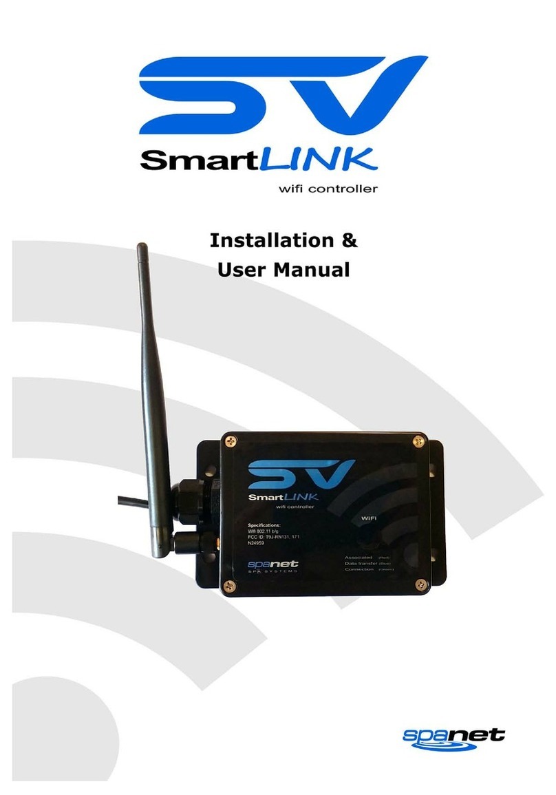
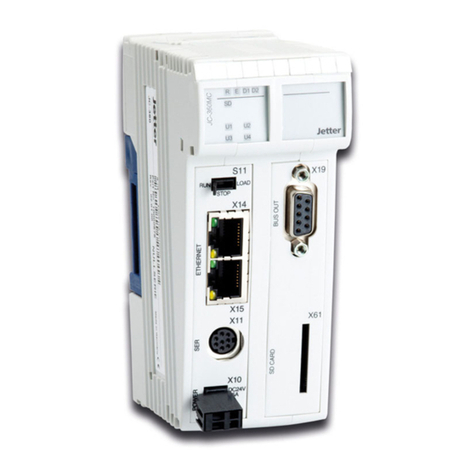
SpaNet SV2 User manual

SV Series Spa Controls
Installation & Technical Manual
SV2 / SV2-VH / SV3 / SV3-VH / SV4-VH

!WARNINGS
Please read the following before installing or connecting this appliance
RISK OF ELECTRICAL SHOCK
SV Series Spa Controls
All electrical connections must be performed by a licensed electrician and
must confirm to all national, state and local electrical codes in effect at the
time of installation.
The appliance should be supplied through a residual current device (RCD)
having a rated residual operating current not exceeding 30mA.
The appliance must be connected to a suitable rated and weather protected
power supply. The supply line should be a dedicated power circuit and
means for disconnection must be incorporated in the fixed wiring in
accordance with your local wiring regulations. Means for disconnection from
the supply mains should have a contact separation in all poles that provide
full disconnection under over voltage Category III conditions.
Earthed appliances must be permanently connected to fixed wiring
(European models only).
The appliance contains no serviceable parts. Do not attempt service of this
control pack. Contact your dealer or authorized service agent for assistance.
Turn the mains power OFF before servicing appliance or modifying any cable
connection
Suitable for indoor use only or when installed under a weatherproof spa
skirt. The appliance should be installed in an enclosure such that all
electrical connections cannot be accessible to the user without the use of a
tool.
Low voltage or improper wiring may cause damage to this appliance. Read
and follow all wiring instructions when connecting to power supply.
Any damaged cable must be replaced immediately.
To prevent electric shock hazard and/or water damage to this appliance, all
unused receptacles must have a water proof seal in place.
Parts incorporating electrical components must be located or fixed so that
they cannot fall into the bath or spa.
Parts containing live parts, except parts supplied with safety extra-low
voltage not exceeding 12V must be inaccessible to a person in the bath or
spa.
This appliance must not be installed in proximity to highly flammable materials.
o
Water temperature in excess of 38 C may cause hyperthermia (heat stress).
It is the spa manufacturer's and/or installer's responsibility to select suitable
loads and configure load shed settings (if required) to ensure the system
does not exceed its rated maximum total load.
It is the installer's responsibility to ensure the floor is capable of supporting
the expected load of the bath or spa and an adequate drainage system has
to be provided to deal with overflow water.
A whirlpool spa should incorporate a water filtration system where the
required level of water purity can be achieved.
An adequate drainage system has to be provided if the equipment is to be
installed in a pit.
This appliance is not intended for use by persons (including children) with
reduced physical, sensory or mental capabilities, or lack of experience and
knowledge, unless they have been given supervision or instruction
concerning use of the appliance by a person responsible for their safety.
Children should be supervised to ensure that they do not play with the
appliance.
1

SV Series Spa Controls
SV Series Specifications
Model No Max Maximum Multi Input Voltage Input Voltage Hz Heater Size
Current Phase Current Single Phase* Three Phase*
SV2 15A - 230-240V AC 400-415V AC 50/60 2kW
SV3 45A - 230-240V AC 400-415V AC 50/60 3kW
SV2-VH 15A 16A per phase 230-240V AC 400-415V AC 50/60 3kW Variable
SV3-VH 45A 25A per phase 230-240V AC 400-415V AC 50/60 6kW Variable
SV4-VH 60A 25A per phase 230-240V AC 400-415V AC 50/60 6kW Variable
* Range of acceptability (+/-6%)
Electrical Specifications
All Models (SV2/SV3/SV2-VH/SV3-VH/SV4-VH)
o
Maximum Controlled Temperature 41 C
o o
Thermal Cut-Out 47 C +/-3 C
o
Maximum Ambient Temperature 40 C
Minimum Flow Rate 65 L/min
RCD trip rating 30mA
Weight (without cable) 5kg
Dimensions (with couplings) 544x309x90mm
Enclosure IPx5
o o
Operating Temperature 0 C to 40 C
o o
Storage Temperature -25 C to 85 C
Humidity up to 85% RH
(non condensing)
System Specifications
Outlet Max Current Output Voltage Hz Typical Accessory
Circ 2A 230-240V AC 50/60 Small Circulation Pump
O3/UV 2A 230-240V AC 50/60 Ozone Generator / UV Sanitiser
Blower 6.3A 230-240V AC 50/60 Air Blower
Pump 1 12A 230-240V AC 50/60 2 Spd Jet Pump / 1 Spd Jet Pump
Pump 2 12A 230-240V AC 50/60 1 Speed Jet Pump
Mains 1 ^ 12A 230-240V AC 50/60 Mains power outlet (always on)
Pump 3 * 12A 230-240V AC 50/60 2 Spd Jet Pump / 1 Spd Jet Pump
Pump 4 # 12A 230-240V AC 50/60 1 Speed Jet Pump
Mains 2 *^ 12A 230-240V AC 50/60 Mains power outlet (always on)
~
Light 1 1A 12V AC LED Light
~
Light 2 * 1A 12V AC LED Light
* Outlets not available on SV2 / SV2-VH models
# Outlet not available on SV2 / SV2-VH / SV3 / SV3-VH models
^ Dedicated mains power outlets (always ON)
~ 1A maximum current draw. This is split between keypads, expand ports and light sockets.
Each socket is rated to 1A maximum so the full 1A can be drawn from a single socket if required.
Output Ratings
2

SV Series Spa Controls
SV Series Overview
3
Mains Power
Terminal Block
Heater Connection
Terminal Block
Earth Bonding
Terminal
Fuse 1
(Phase 3 Loads)
Fuse 2
(Phase 2 Loads)
Fuse 3
(Phase 1 Loads)
Heater Tube
AMP Power Outlets
(230-240V AC)
for spa accessories:
circ, o /uv, air blower
3
jet pumps, auxiliaries
Coupling
(tail & nut)
Coupling
(tail & nut)
Wall Mount
Bracket
Wall Mount Bracket
Heartbeat LED
Low Voltage Connections
(12V)
keypads, lights, in-pool sensor
digital/analog expand ports
Mains Power
Cable Entry
Points
Mounting Foot
Heater Cover Plate
(remove to access
heater connections)
DIP Switch Bank
TM

SV Series Spa Controls
Electrical Wiring (Terminal Block Connections)
AUS / NZ / European Models (230-240V AC)
230-240V (5 wire) three phase
11
230-240V (3 wire) single phase
Terminal Wiring
P3 Link to CS
P2 Link to CS
CS Link to P3 and P2
P1 Phase
G Earth
N Neutral
*Dip Switch 5 OFF
*Dip Switch 6 OFF
230-240V (4 wire) dual phase
Terminal Wiring
P3 Link to CS
P2 Phase 2
CS Link to P3
P1 Phase 1
G Earth
N Neutral
*Dip Switch 5 ON
*Dip Switch 6 OFF
Terminal Wiring
P3 Phase 3
P2 Phase 2
CS Not used
P1 Phase 1
G Earth
N Neutral
*Dip Switch 5 ON
*Dip Switch 6 ON
Tools Required: Wire Strippers, Phillips head screwdriver, flat head screwdriver
Remove five (5) x Phillips screws from mains lid to access terminal block.
Cut away appropriate length of outer insulation from mains power cable and
strip away 25mm (1") of wire insulation from the end of each wire.
Route mains cable through one of the two snap out holes provided and
secure the cable with a gland to provide adequate cable strain relief
(Tighten gland with use of a tool to ensure supply line anchorage point
cannot be removed by hand).
Push the wires into the correct terminals as labelled. Refer wiring guide below
or on the sticker inside the terminal block area.
Tighten all screws on the terminal block with a screwdriver and check to
ensure each wire has been firmly secured. Then screw mains lid back on.
WARNING
This appliance must be supplied through a residual current device
(RCD) having a rated residual operating current not exceeding 30mA.
Correct wiring of the main electricity board, RCD and spa pack is critical.
.
When installing appliance refer to your local wiring regulations.
When installing mains power cable providing service loops (additional wire
length for future serviceability) to incoming wiring is recommended.
* Refer Dip switch information on page 11
N
P1
P2
CS
P3
G
N
P1
P2
CS
P3
G
N
P1
P2
CS
P3
G
Other manuals for SV2
2
This manual suits for next models
4
Table of contents
Other SpaNet Controllers manuals
