sparkfun NEO-M9N Technical document

SparkFun GPS NEO-M9N Hookup Guide
Introduction
The SparkFun GPS NEO-M9N is the next iteration of u-blox's GPS offerings! We've developed two flavors of the
board: one with a small chip antenna and another with a u.FL connector so that you can select an antenna of your
choosing.
SparkFun GPS Breakout - NEO-M9N, Chip Antenna
(Qwiic)
GPS-15733

Required Materials
To follow along with this tutorial, you will need the following materials. You may not need everything though
depending on what you have. Add it to your cart, read through the guide, and adjust the cart as necessary.
SparkFun GPS Breakout - NEO-M9N, U.FL (Qwiic)
GPS-15712
Product Showcase: SparkFun GPS Breakout NEO-MProduct Showcase: SparkFun GPS Breakout NEO-M……

Additional GPS Antenna Options
Below are some other GPS Antenna options. Some of the options below have an SMA connector, so make sure to
get the u.FL to SMA cable if you decide to use those. Link for that is below in the GPS accessories. If you want to
try different chip antennas, then try the GNSS Antenna Evalutation Board listed below and make sure to get the
u.FL to u.FL connector in the accessories.
SparkFun RedBoard Qwiic
DEV-15123
Qwiic Cable - 100mm
PRT-14427
USB micro-B Cable - 6 Foot
CAB-10215
GPS/GNSS Magnetic Mount Antenna - 3m
(SMA)
GPS-14986
GPS/GNSS Embedded Antenna - 1m (SMA)
GPS-14987
SparkFun GNSS Chip Antenna Evaluation
Board
GPS Embedded Antenna SMA
GPS-00177


Heads up! If you are using the RedBoard without a Qwiic connector, we recommend getting the Qwiic
Shield for Arduino.
Suggested Reading
If you aren't familiar with the Qwiic system, we recommend reading here for an overview.
Qwiic Connect System
We would also recommend taking a look at the following tutorials if you aren't familiar with them.
Qwiic Cable - 200mm
PRT-14428
Qwiic Cable - 50mm
PRT-14426
SparkFun Qwiic Shield for Arduino
DEV-14352

Hardware Overview
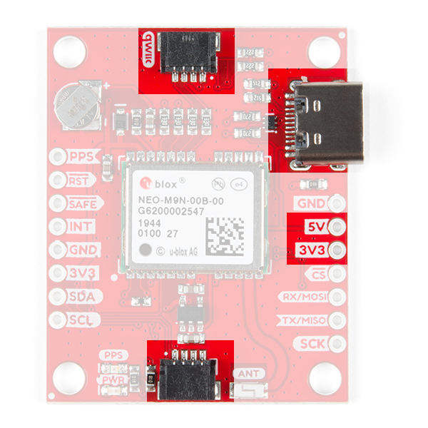
Power
Power for this board is 3.3V and we have provided multiple power options. This first and most obvious is the USB-
C connector. Secondly, are the Qwiic Connectors on the top and bottom of the board. Thirdly, there is a 5V pin
on the PTH header along the side of the board that is regulated down to 3.3V. Make sure that power your provide
to this pin does not exceed 6 volts. Finally, just below the 5V pin is a 3.3V pin that should only be provided a clean
3.3V power signal.
GPS Basics
The Global Positioning System (GPS) is an
engineering marvel that we all have access to for a
relatively low cost and no subscription fee. With the
correct hardware and minimal effort, you can determine
your position and time almost anywhere on the globe.
Serial Peripheral Interface (SPI)
SPI is commonly used to connect microcontrollers to
peripherals such as sensors, shift registers, and SD
cards.
I2C
An introduction to I2C, one of the main embedded
communications protocols in use today.
How to Work with Jumper Pads and PCB Traces
Handling PCB jumper pads and traces is an essential
skill. Learn how to cut a PCB trace, add a solder
jumper between pads to reroute connections, and
repair a trace with the green wire method if a trace is
damaged.
Getting Started with U-Center for u-blox
Learn the tips and tricks to use the u-blox software tool
to configure your GPS receiver.
Three Quick Tips About Using U.FL
Quick tips regarding how to connect, protect, and
disconnect U.FL connectors.

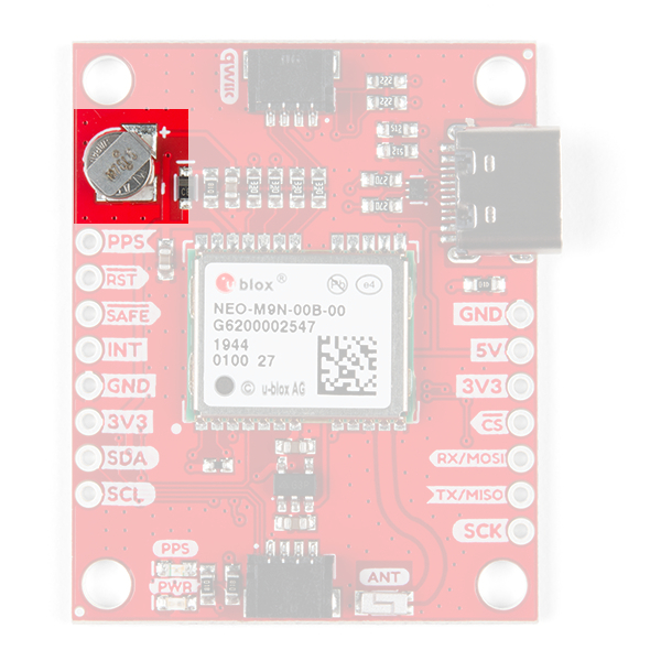
Battery
The small metal disk in the upper left corner is a small lithium battery. This battery does not provide power to the
IC like the 3.3V system does, but to relevant systems inside the IC that allow for a quick reconnection to satellites.
The time to first fix will about ~29 seconds, but after it has a lock, that battery will allow for a two second time to
first fix. This is known as a hot start and lasts for four hours after the board is powered down. The battery provides
over a years worth of power to the backup system and charges slowly when the board is powered. To charge it to
full, leave your module plugged in for 48 hours.
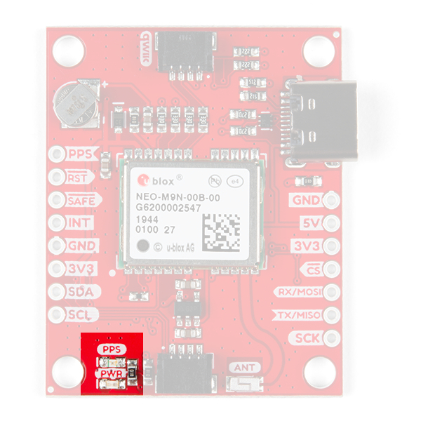
LEDs
There's is a red power LED just to the left of the bottom Qwiic connector and near the board's edge to indicate that
the board is powered. There is another LED just above the power LED labeled PPS that is connected to the Pulse
Per Second line. When connected to a satellite, this line generates a pulse that is synchronized with a GPS or
UTC time grid. By default, you'll see one pulse a second.

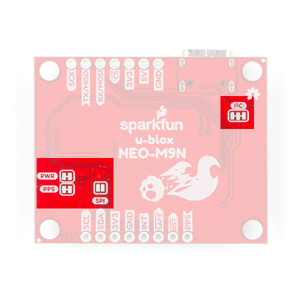
Jumpers
There are four jumpers on the underside of the product, each labeled with its function. At the upper right of the
picture is a three way jumper labeled I²C that connects two pull-up resistors to the I C data lines. If you have
many devices on your I C data lines, then you may consider cutting these. On the left side of the board is a jumper
labeled PWR . If you cut this trace it will disconnect the Power LED. Just below is the PPS jumper that when cut
disconnects the PPS LED. Finally, there's a jumper labeled SPI which enables the SPI data bus thus disabling the
UART functions on those lines. For more information, check out our tutorial on working with jumper pads and PCB
traces.
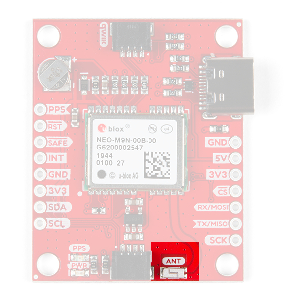
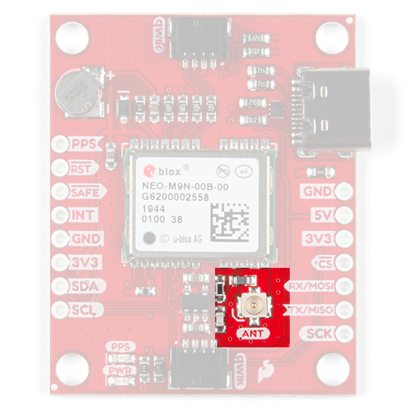
Chip Antenna or U.FL Connector
The SparkFun GPS NEO-M9N with Chip Antenna has a GNSS antenna near its left Qwiic connector while its
cousin has a U.FL connector in which you can connect a patch antenna.
2
2

Chip Antenna U.FL
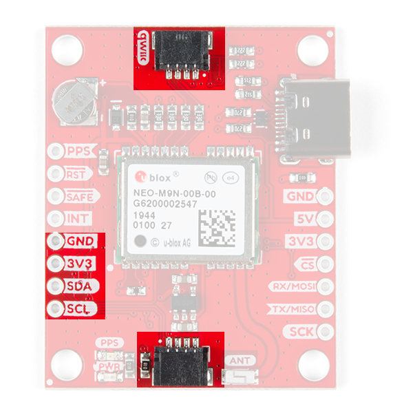
Qwiic and I C
There are two pins labeled SDA and SCL which indicates the I C data lines. Similarly, you can use either of the
Qwiic connectors to provide power and utilize I C. The Qwiic ecosystem is made for fast prototyping by removing
the need for soldering. All you need to do is plug a Qwiic cable into the Qwiic connector and voila!
The only I C address for this and all u-Blox GPS products is 0x42, though each can have their address
changed through software.
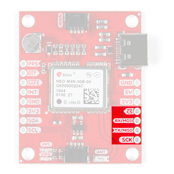
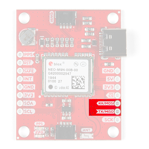
SPI
There are four pins on the right most header that are labeled with their corresponding SPI functionality. As
mentioned in the jumpers section, you'll need to close the SPI jumper on the underside to enable SPI.
2
2
2
2

UART
There are two pins on the right most header labeled for their UART functionality.
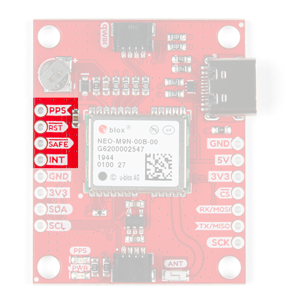
Broken Out Pins
There are four other pins broken out: Pulse per second ( PPS ), Reset ( RST ), Safeboot ( SAFE ), and finally the
interrupt pin ( INT ). The first pin PPS , outputs pulse trains synchronized with the GPS or UTC time grid. The signal
defaults to once per second but is configurable over a wide range. Read the u-blox Receiver Protocol
Specification in the Resources and Going Further tab for more information. The reset pin resets the chip. The
next pin, SAFE is used to start up the IC in safe boot mode, this could be useful if you somehow manage to corrupt
the module's Flash memory. The final pin INT can be used to wake the chip from power save mode.

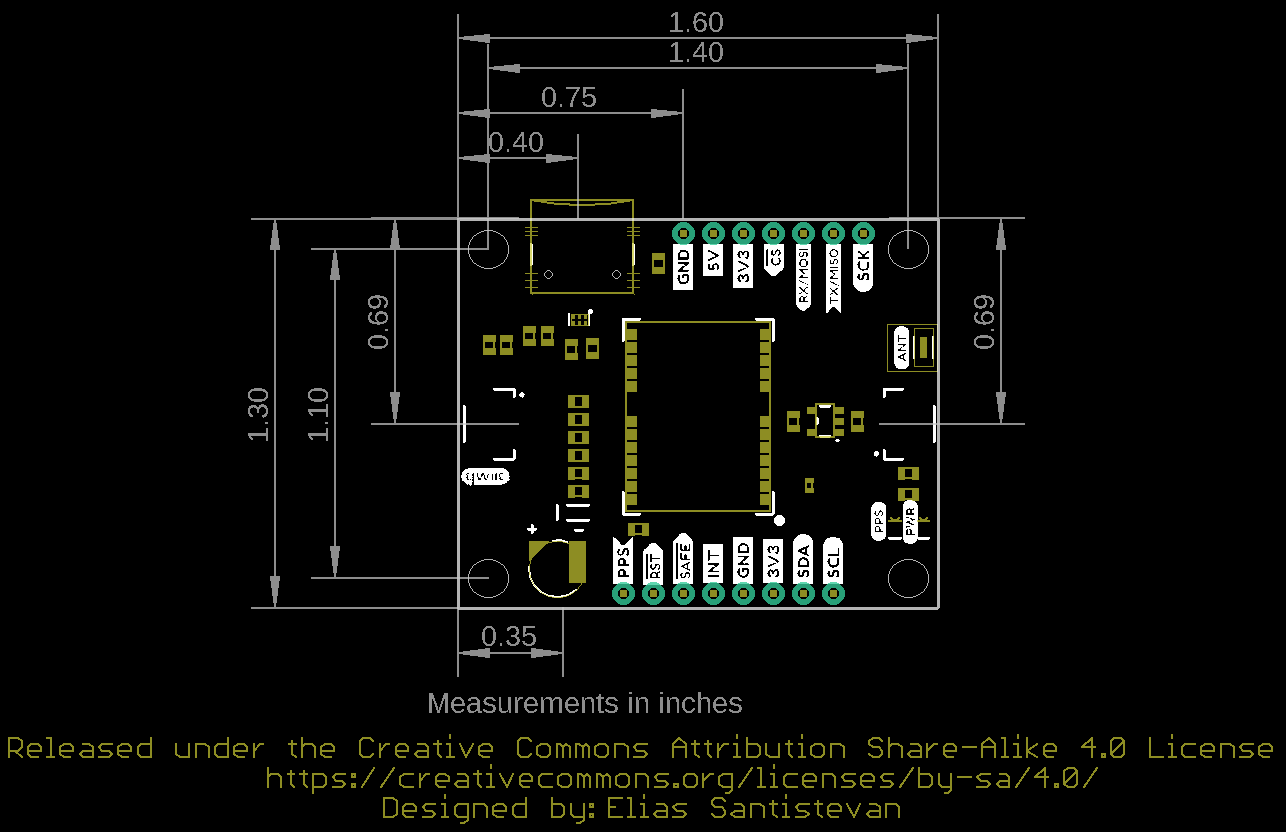
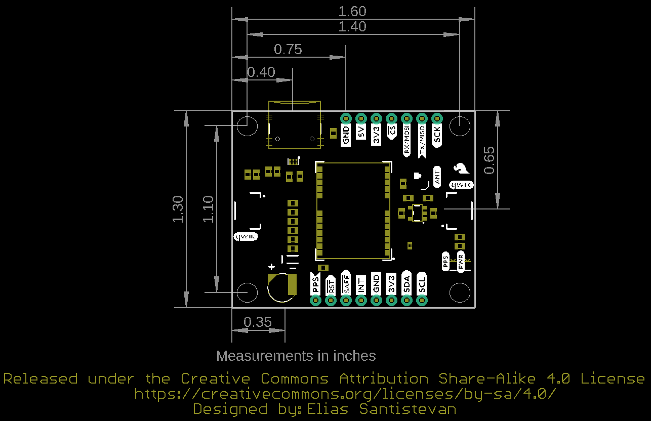
Board Dimensions
Overall, the boards are 1.30"x1.60". The location of a majority of the components are the same with the exception
of the SMD chip antenna and the u.FL connector.
Chip Antenna Version u.FL Version
Click on image for a closer view.
GPS Capabilities
The SparkFun NEO-M9N is able to connect to up to four different GNSS constellations at a time making it very
accurate for its size. Below are the listed capabilities of the GPS unit when connecting to multiple GNSS
constellations and when connecting to a single constellation.
Constellations GPS+GLO+GAL+BDS GPS+GLONASS+GAL GPS+GLO GPS+BDS
Horizontal
Position
Accuracy
2m 2m 2m 2m
Max
Navigation
Update Rate
PVT 25Hz 25Hz 25Hz 25Hz

When using a single GNSS constellation:
Constellation GPS GLONASS BEIDOU Galileo
Horizontal Position Accuracy 2m 4m 3m 3m
Max Navigation Update Rate PVT 25Hz 25Hz 25Hz 25Hz
Time-To-First-Fix Cold Start 29s 27s 32s 42s
Hot Start 2s 2s 2s 2s
Sensitivity Tracking and Navigation -166dBm -164dBm -160dBm -159dBm
Reacquisition -160dBm -155dBm -157dBm -154dBm
Cold Start -148dBm -145dBm -145dBm -140dBm
Hot Start -159dBm -156dBm -159dBm -154dBm
Velocity Accuracy 0.05m/s 0.05m/s 0.05m/s 0.05m/s
Heading Accuracy 0.3deg 0.3deg 0.3deg 0.3deg
Hardware Assembly
Update Rate
Time-To-First-
Fix
Cold Start 24s 25s 26s 28s
Hot Start 2s 2s 2s 2s
Sensitivity Tracking and
Navigation
-167dBm -167dBm -167dBm -1667dBm
Reacquisition -160dBm -160dBm -160dBm -160dBm
Cold Start -148dBm -148dBm -148dBm -148dBm
Hot Start -159dBm -159dBm -159dBm -159dBm
Velocity
Accuracy
0.05m/s 0.05m/s 0.05m/s 0.05m/s
Heading
Accuracy
0.3deg 0.3deg 0.3deg 0.3deg

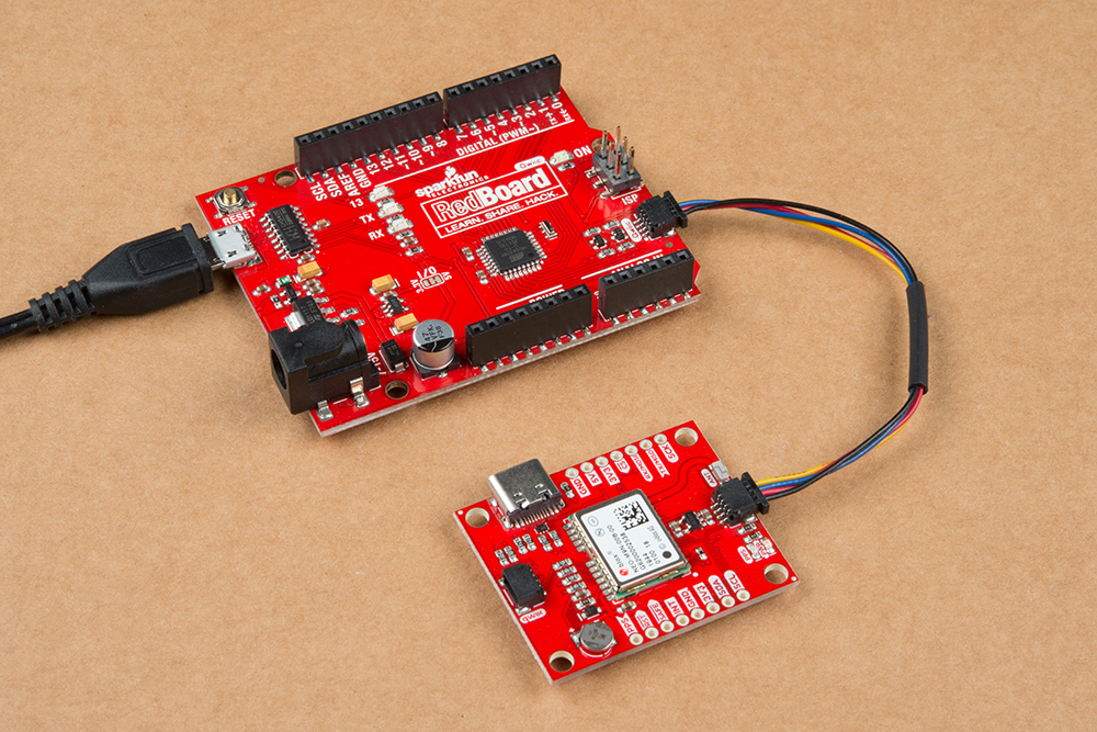
For this example, I used a Qwiic capable RedBoard and associated USB cable. connecting the boards with Qwiic
cable, the assembly is very simple. Plug a Qwiic cable between the RedBoard and the SparkFun NEO-M9N with
chip antenna and that's it! Just as easily I could have used the version with the U.FL connector and plugged in one
of our patch antennas to the GPS board. If you need tips on plugging in the U.FL connector, then check out our
U.FL tutorial. If you're going to be soldering to the through hole pins for I C functionality, then just attach lines to
power, ground, and the I C data lines to a microcontroller of your choice.
SparkFun U-Blox Library
Note: This example assumes you are using the latest version of the Arduino IDE on your desktop. If this is
your first time using Arduino, please review our tutorial on installing the Arduino IDE. If you have not
previously installed an Arduino library, please check out our installation guide.
All of our u-blox based GPS boards share the same library: these two boards, their predeccesors and the higher
precision u-blox cousins. The SparkFun U-blox Arduino library can be downloaded with the Arduino library
manager by searching 'SparkFun Ublox' or you can grab the zip here from the GitHub repository to manually
install.:
SPARKFUN U-BLOX ARDUINO LIBRARY (ZIP)
There are 13 example sketches provided to get you up and receiving messages from space. We'll go over one of
the examples in this tutorial.
Note: Example 2 uses the 'MicroNMEA' library by Steve Marple. Make sure to install the library as well by
searching for it in the Arduino library manager. You could also grab the zip here from the GitHub repository to
manually install.
MICRONMEA ARDUINO LIBRARY (ZIP)
Example Code
We're just going to look at example two (i.e. "Example2_NMEAParsing.ino") which in my opinion, makes it clear
the awesomeness of these GPS receivers. That is to say, talking to satellites and finding out where in the world
you are.
2
2

#include <Wire.h> //Needed for I2C to GPS
#include "SparkFun_Ublox_Arduino_Library.h" //Click here to get the library: http://librarymanag
er/All#SparkFun_Ublox_GPS
SFE_UBLOX_GPS myGPS;
void setup()
{
Serial.begin(115200);
Serial.println("SparkFun Ublox Example");
Wire.begin();
if (myGPS.begin() == false)
{
Serial.println(F("Ublox GPS not detected at default I2C address. Please check wiring. Freezi
ng."));
while (1);
}
//This will pipe all NMEA sentences to the serial port so we can see them
myGPS.setNMEAOutputPort(Serial);
}
void loop()
{
myGPS.checkUblox(); //See if new data is available. Process bytes as they come in.
delay(250); //Don't pound too hard on the I2C bus
}
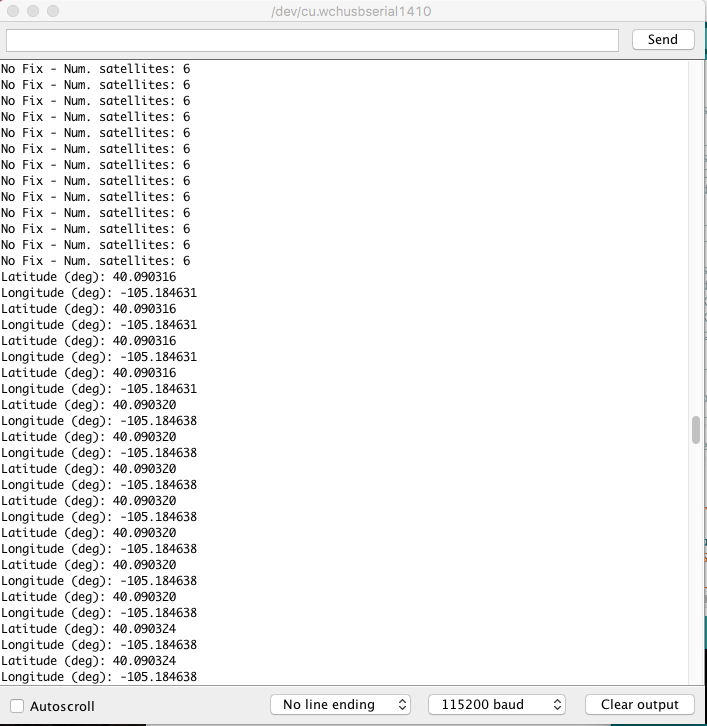
When you upload this code you'll have to wait ~29s to get a lock onto any satellites. After that first lock, the backup
battery on the board will provide power to some internal systems that will allow for a hot start the next time you
turn on the board. The hot start only lasts four hours, but allows you to get a lock within one second. After you get
a lock the serial terminal will start listing longitude and latitude coordinates, as seen below. Make sure to set the
serial monitor to 115200 baud.

These are the coordinates for SparkFun HQ
Resources and Going Further
Now that you've successfully got your GPS receiver up and running, it's time to incorporate it into your own project!
For more information, check out the resources below:
SparkFun u-Blox NEO-M9N with Chip Antenna
Schematic (PDF)
Eagle Files (ZIP)
Board Dimensions
SparkFun u-Blox NEO-M9N with U.FL Connector
Schematic (PDF)
Eagle Files (ZIP)
Board Dimensions
u-blox Module Documentation
NEO-M9N Datasheet (PDF)
Protocol Summary (PDF)
Integration Manual (PDF)
u-blox Protocol Specification (PDF)
u-center Software
GitHub
Product Repo
SparkFun u-blox Arduino Library
SFE Product Showcase
Are you looking for a GPS receiver with an insane 10mm 3D accuracy, then check out the two other u-Blox based
GPS boards by SparkFun (ZED-F9P and NEO-M8P-2) on the left below. Need a smaller more compact GPS unit
but don't need as high of a refresh rate, check out the ZOE-M8Q and SAM-M8Q on the right.

Need some inspiration for your next project? Check out some of these related tutorials:
SparkFun GPS-RTK2 Board - ZED-F9P (Qwiic)
GPS-15136
SparkFun GPS-RTK Board - NEO-M8P-2
(Qwiic)
GPS-15005
SparkFun GPS Breakout - ZOE-M8Q (Qwiic)
GPS-15193
SparkFun GPS Breakout - Chip Antenna, SAM-
M8Q (Qwiic)
GPS-15210
LS20031 5Hz (66 Channel) GPS Receiver
Hookup Guide
In this tutorial, we will solder headers to the surface
mount pads of the LS20031 GPS receiver and read the
output using an Arduino!
Getting Started with the GeoFence
How to get started using the GeoFence GPS Boundary
Widget and GeoFence Software.
New!

Displaying Your Coordinates with a GPS Module
This Arduino tutorial will teach you how to pinpoint and
display your GPS coordinates with a press of a button
using hardware from our Qwiic Connect System (I2C).
Getting Started with the Autonomous Kit for the
Sphero RVR
Want to get started in robotics? Look no further than
the SparkFun autonomous kit for the Sphero RVR!
Whether you purchased the Basic or Advanced kit, this
tutorial will get you rolling...
Table of contents
Other sparkfun GPS manuals

Popular GPS manuals by other brands

EverMore
EverMore BT-R900 user manual

TBIT
TBIT WA-100 installation instructions

BW SENSING
BW SENSING GI920 Series installation instructions

ACR Electronics
ACR Electronics RESQFIX 406 Product support manual

Garmin
Garmin GPSMAP 2006 owner's manual

Panasonic
Panasonic KXG5500 - GPS RECEIVER operating instructions


