SPARKOE Home User manual

HOME
USER MANUAL
Fast Level 2 Eletric Vehicle Charger

THANK
YOU
for accelerating
Earth's transition to
sustainable energy.
WARNING
01 02
Circuit Breaker Options table
Output Amperage (A)
Circuit Breaker Options (A)
16A
20A
32A
40A
40A
50A
48A
60A
WARNING
This manual contains important instructions for the Sparkö Home
series that shall be followed during installation, operation and
maintenance of the unit.
WARNING
AVERTISSEMENT
Ce manuel contient des instructions importantes pour les modèles :
série EVC12 qui doit être suivie pendant l'installation, le fonctionne-
ment et la maintenance de l'unité.
1. Important Safety Instructions
Read all the instructions before using this product.
This device should be supervised when used around children.
Do not put fingers into the electric vehicle connector.
Do not use this product if the flexible power cord or EV cable is frayed,
has broken insulation, or any other signs of damage.
Do not use this product if the enclosure or the EV connector is broken,
cracked, open, or shows any other indication of damage.
To reduce the risk of fire, connect only to a circuit provided branch
circuit over-current protection in accordance with the CSA C22.1–15
Canadian Electrical Code, Part 1 (Canada) or NOM-001-SEDE Electrical
installations (utility) (Mexico) or ANSI / NFPA 70 National Electrical
Code (USA).
To avoid a risk of fire or electric shock, do not use this device with an
extension cord.
THE SUITABILITY OF THE USE OF FLEXIBLE CORD IN ACCORDANCE
WITH CE CODE, PART I, RULE 4-012, IS TO BE DETERMINED BY THE
LOCAL INSPECTION AUTHORITY HAVING JURISDICTION.
Risk of electric shock. Do not remove cover or attempt to open the
enclosure. No user serviceable parts inside. Refer servicing to qualified
service personnel.
1
2
3
4
5
6
7
8
9
Lisez toutes les instructions avant d'utiliser ce produit.
Cet appareil doit être surveillé lorsqu'il est utilisé à proximité d'enfants.
Ne pas mettre les doigts dans le connecteur du véhicule électrique.
N'utilisez pas ce produit si le cordon d'alimentation flexible ou le câble EV
est effiloché, a une isolation cassée, ou tout autre signe de dommage.
N'utilisez pas ce produit si le boîtier ou le connecteur EV est cassé,
fissuré, ouvert ou montre toute autre indication de dommage.
Pour réduire les risques d'incendie, ne connecter qu'à un circuit
protection contre les surintensités des circuits de dérivation conformé-
ment à la norme canadienne CSA C22.1-15 Code électrique, partie 1
(Canada) ou NOM-001-SEDE Installations électriques (service public)
(Mexique) ou ANSI / NFPA 70 National Electrical Code (États-Unis).
Pour éviter tout risque d'incendie ou de choc électrique, n'utilisez pas
cet appareil avec une rallonge.
L'ADÉQUATION DE L'UTILISATION DU CORDON FLEXIBLE SELON LE
CODE CE,LA PARTIE I, RÈGLE 4-012, DOIT ÊTRE DÉTERMINÉE PAR
L'AUTORITÉ LOCALE D'INSPECTION AYANT JURIDICTION.
Risque de choc électrique. Ne retirez pas le couvercle et n'essayez pas
d'ouvrir le boîtier. Aucun utilisateur pièces réparables à l'intérieur.
Confiez l'entretien à un personnel d'entretien qualifié.
1
2
3
4
5
6
7
8
9
Circuit Breaker Options table
Output Amperage (A)
Circuit Breaker Options (A)
16A
20A
32A
40A
40A
50A
48A
60A

WARNING
03 04
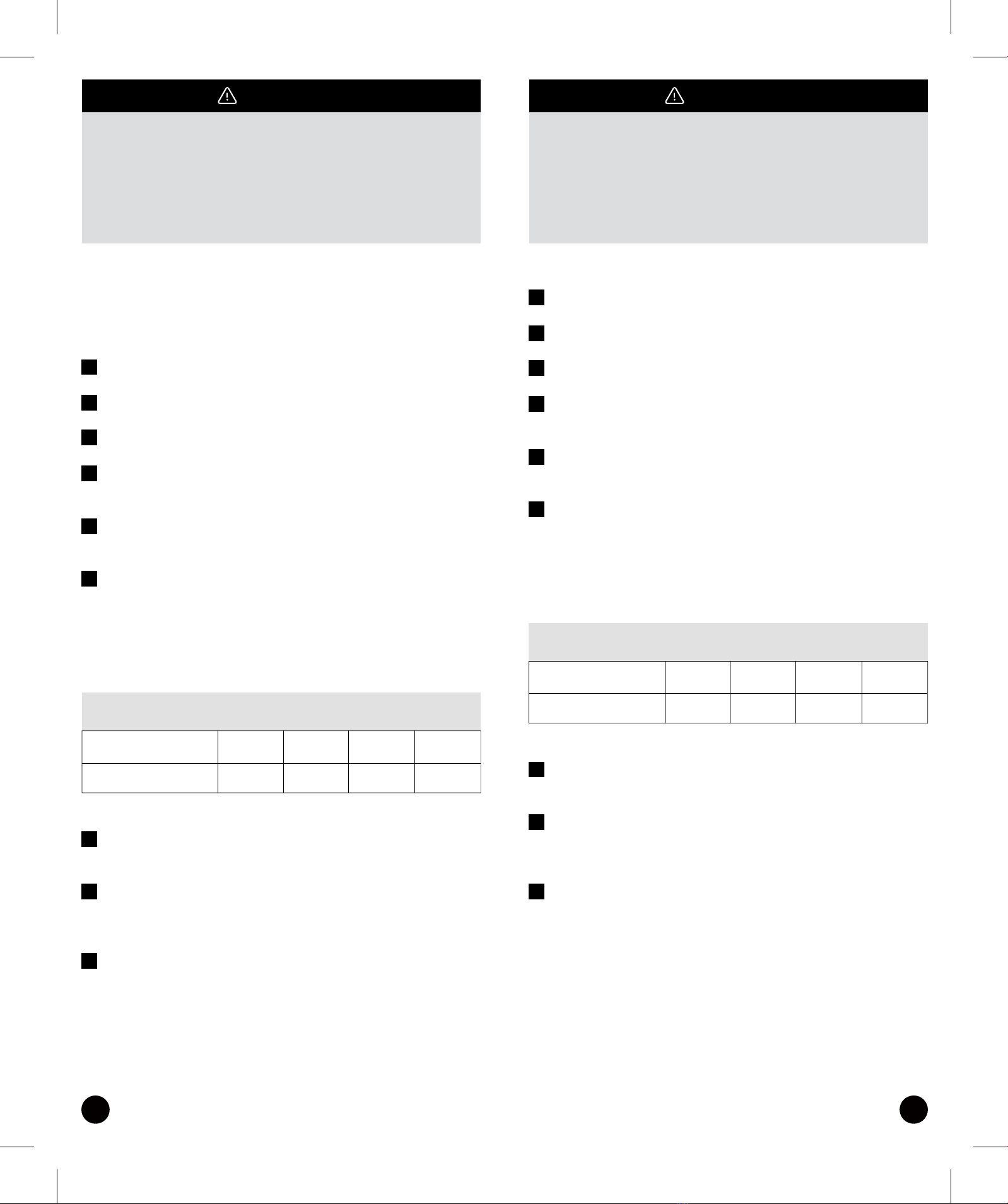
Rear Notch
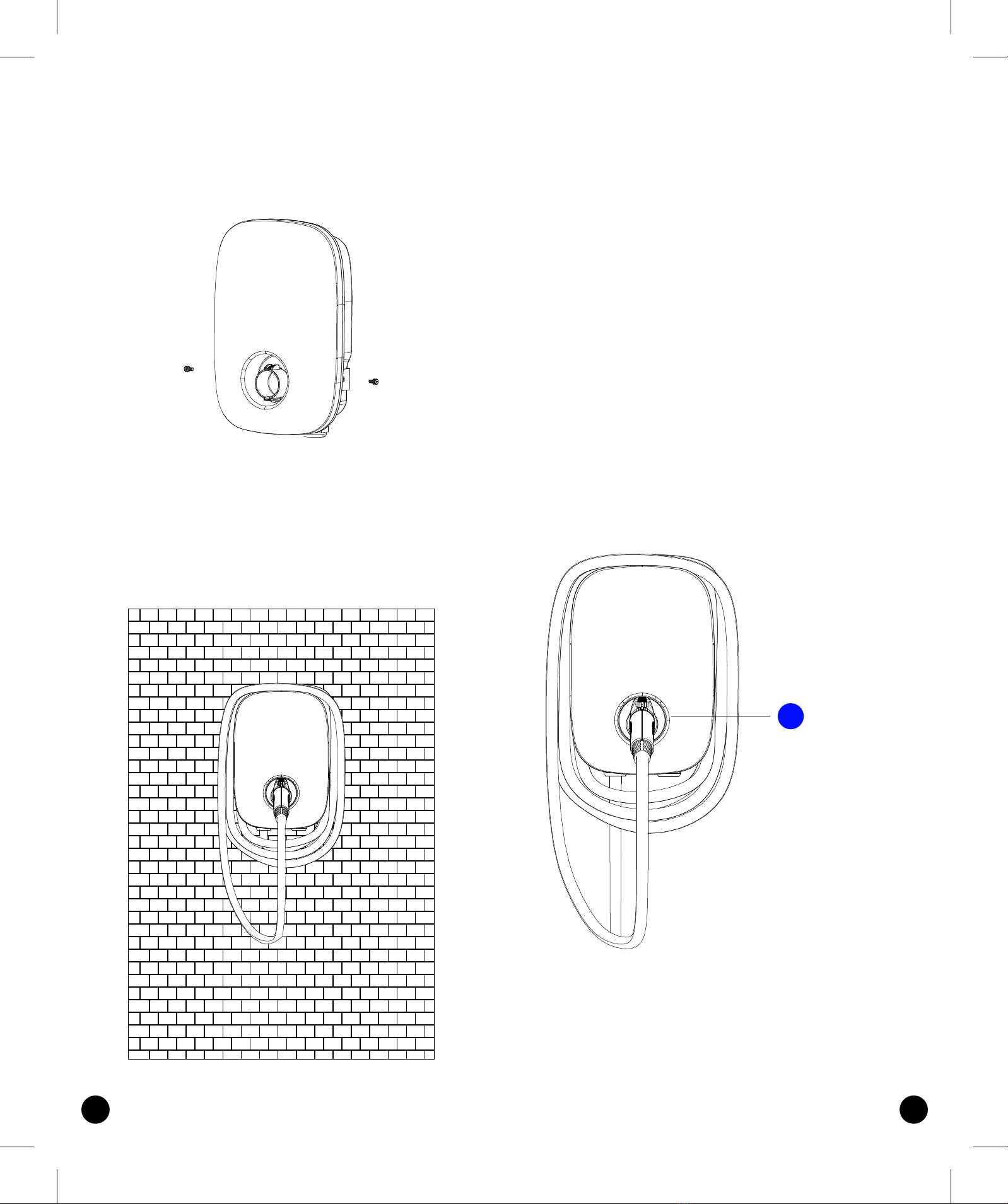
Charging Cable Inlet AC Power Inlet
LAN Cable Inlet
LED Light
Indication
SAE J1772
AC Charging
Connector
This device complies with part 15 of the FCC Rules.
Operation is subject to the following two conditions:
This device may not cause harmful interference, and this device must
accept any interference received, including interference that may cause
undesired operation.
Caution: Changes or modifications to this unit not expressly approved by
the party responsible for compliance could void the user's authority to
operate the equipment.
This equipment has been tested and found to comply with the
limits for a Class A digital device, pursuant to part 15 of the FCC
Rules. These limits are designed to provide reasonable protec-
tion against harmful interference when the equipment is
operated in a commercial environment. This equipment
generates, uses, and can radiate radio frequency energy and, if
not installed and used in accordance with the instruction
manual, may cause harmful interference to radio communica-
tions. Operation of this equipment in a residential area is likely
to cause harmful interference in which case the user will be
required to correct the interference at his own expense.
WIFI module:Contians FCC ID:2AC7Z-ESPWROOM32D
LTE module:Contians FCC ID:XMR202008EC25AFXD
To satisfy FCC RF exposure requirements, a separation distance
of 20cm or more should be maintained between the antenna of
this device and persons during device operation. To ensure
compliance, operations at closer than this distance is not
recommended.
2. Basic Interface
NOTE:
WARNING
05 06
14.23"
9.84"
4.40"
UL 2594: Electric Vehicle Supply Equipment
UL 2231-1: Personnel Protection Systems for Electric Vehicle (EV) Supply
Circuits: General Requirements
UL 2231-2: Personnel Protection Systems for Electric Vehicle (EV) Supply
Circuits: Particular Requirements for Protection Devices for Use in Charging
Systems
UL 2251: Plugs, Receptacles and Couplers for Electric Vehicles
UL 62: Flexible Cords and Cables
UL 991: Tests for Safety-Related Controls Employing Solid-State Devices
UL 1998: Software in Programmable Componets
NFPA 70 Article 625: National Electrical Code, Electric Vehicle Charging System
UL 840 (Clearance and Creepage)
4. Design Standard
3. Dimensions

*1 LAN Version and Wi-Fi & Bluetooth Version
*2 Wi-Fi & Bluetooth Version
Model Name
Rated Input Voltage
Rated Output Current
AC Power Frequency
Input Protection
Output Protection
Output Interface
Storage Temperature
Operation Temperature
Relative Operation Humidity
Relative Storage Humidity
Version
RJ45 Cable Inlet*1
Wi-Fi Function*2
Cable Length
Protection Level
Installation Type
Altitude
Status Indication
200-240 VAC
16/32/40/48A
60 Hz
UVP, OVP, RCD, SPD, Ground Fault Protection
OCP, OTP, Control Pilot Fault Protection
SAE J1772 AC Charging Connector
-40°F to 158°F
-22°F to 122°F
95% RH Maximum
95% RH Maximum
LAN Version / Wi-Fi Bluetooth Version
10M / 100M Base-T
802.11 b/g/n
18ft
Type 3
Wall-Mounted
Red, Green, Blue LED
07 08
5. Status Description of the
Charger Indication Light
Standby - Blue Light
The READY light stays
steady in standby mode.
Waiting for Charging - Green
Light After the vehicle connec-
tor is connected to the vehicle
inlet, the CHARGE light is
constantly lit.
Charging - Green Light
Flashing The CHARGE light
flashes while charging.

No.
1
2
3
4
5
Product Name
AC Charger (With Charging Cable)
User Manual
Wall-Mounted Bracket
M5 teeth screws
Quantity
1
1
1
2
M6 Hexagonal Expansion Screws 4
Note
7. Packing List
4
5
1 2
FAULT
3
09 10
Fault - Red Light The red light is
lit while fault. Please refer to "9.3
Error and Warning Messages"
for detailed information.
8. Installation Instructions
8.1 Safety Requirements
• Be sure to preview the user manual and ensure local building and
electrical codes are reviewed before installing the AC charger.
• The AC charger should be installed by a qualified technician according to
the user manual and local safety regulations.
• Use appropriate protection when connecting to the main power
distribution cable.
• Type B, C or D breaker with the rating current for table should be installed
in the upstream AC distribution box.
• Disconnect switch for each ungrounded conductor of AC input shall be
provided by others in accordance with the National Electric Code,
ANSI/NFPA 70.
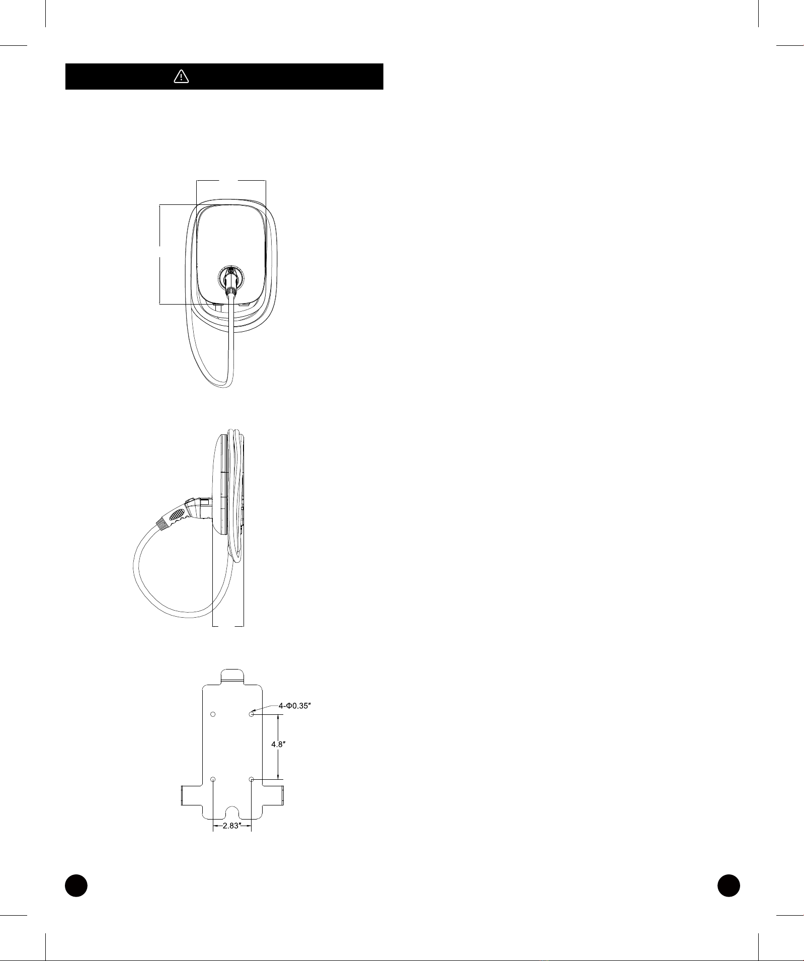
L1 L2 PE
Circuit Breaker Options table
Output Amperage (A)
Circuit Breaker Options (A)
16A
20A
32A
40A
40A
50A
48A
60A
11 12
GROUNDING INSTRUCTIONS
This product must be grounded. If it should malfunction or break down,
grounding provides a path of least resistance for electric current to reduce
the risk of electric shock. This product is equipped with a cord having an
equipment grounding conductor and a grounding plug. The plug must be
plugged into an appropriate outlet that is properly installed and grounded
in accordance with all local codes and ordinances.
IAVERTISSEMENT - Une mauvaise connexion du conducteur de mise à la
terre de l'équipement peut entraîner un risque de choc électrique. Vérifiez
auprès d'un électricien ou d'un technicien qualifié si vous n'êtes pas sûr que
le produit soit correctement mis à la terre. Ne modifiez pas la fiche fournie
avec le produit - si elle ne rentre pas dans la prise, faites installer une prise
appropriée par un électricien qualifié.
For safe use of electricity, please add circuit breaker protection in the input
part of charging pile. Connect the L1 lead to the grid L1, connect the L2
lead to the grid L2, connect the PE lead to the grid PE (for all Version).
WARNING – Improper connection of the equipment-grounding
conductor is able to result in a risk of electric shock. Check
with a qualified electrician or serviceman if you are in doubt as
to whether the product is properly grounded. Do not modify
the plug provided with the product – if it will not fit the outlet,
have a proper outlet installed by a qualified electrician.
8.2 Wiring

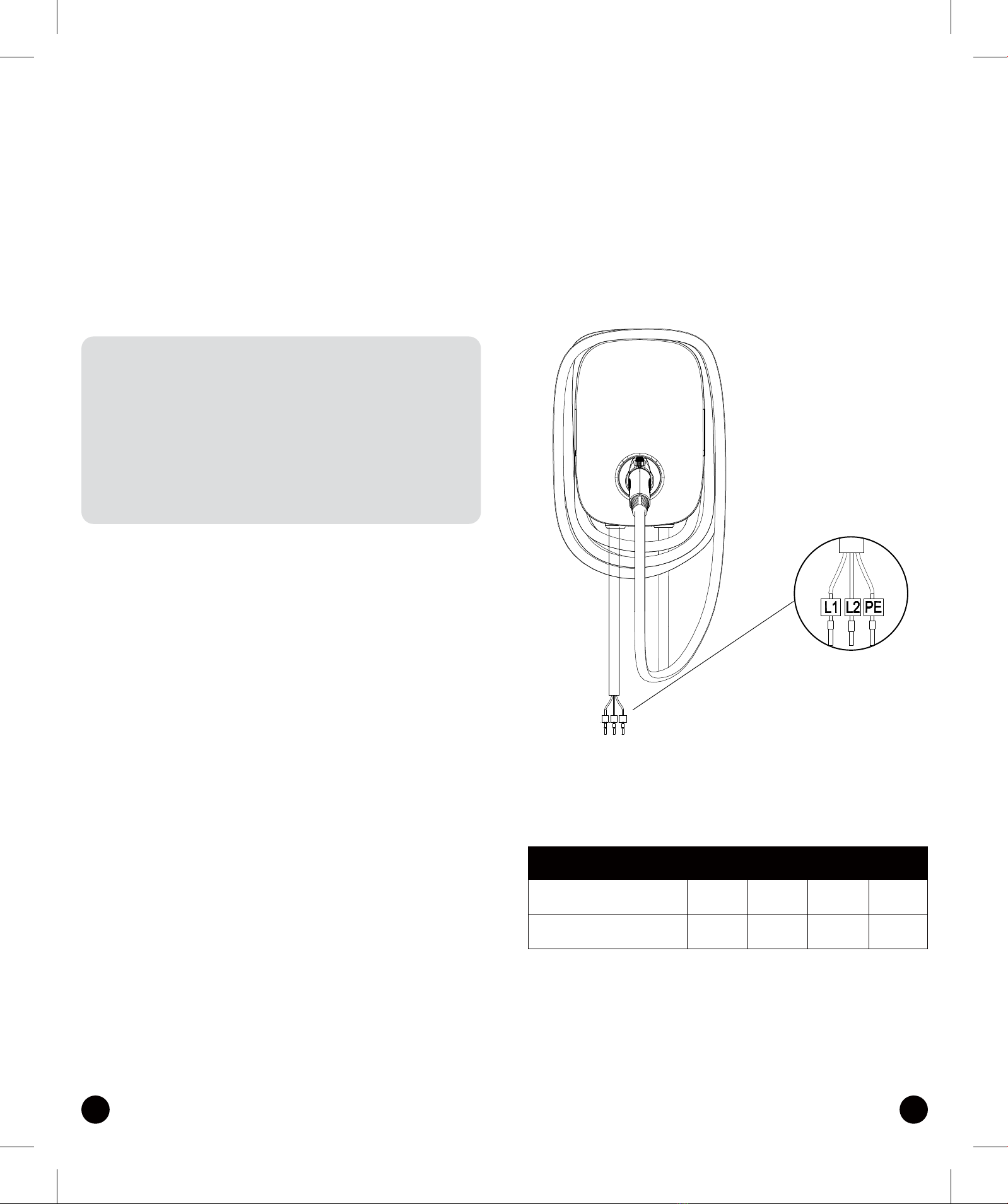
8.4 Wall-Mounted Bracket Installation
13 14
Tools required before installing the Wall-Mounted charger, gather the
following tools:
• Wire stripper
• Crimpers for European terminals
• Phillips screwdriver for M5
• Slotted screwdriver for 4~5.5MM
• Adjustable Wrench M6
• Head gasket screw 10-10.5mm
• Voltmeter or digital multi-meter (for measuring AC voltage at the
installation site)
• The inserting cable should meet the best waterproof performance. It is
recommended to use 3 core / 7AWG cable (XLPE or equivalent cable) to
pull the cable from the distribution box.
• Level ruler
• Pencil or marker
• Machine drill
Step 1:
• Set the positions of the 4 screw holes and drill them, with a diameter of
8mm and
a depth of 52mm.
• Use 4 sets expansion screw and M6 screw to fix the wall-mounted bracket
on the wall.
Step 2:
Align the rear notch of charger into the wall-mounted bracket and fit the
screw holes of the right and left side.
Installation Instructions
“This device shall be mounted at a sufficient height from
grade such that the height of the storage means for the
coupling device is located between 600mm (24 inches) and
1.2m (4 feet) from grade.”
8.3 Tools and Materials Required
READY
15 16
9. Operation Instuctions
Step 3:
Fix two M5 screws to complete the installation. 9.1 Operating Procedures
User authorization
Connect to Vehicle Charging Inlet
Charging Message
Charging completed
9.2 Operating Steps
Step 1 / Standby Mode
After power-on, blue light (READY), green light (CHARGE) and red light
(FAULT) all lit.
Enter standby mode and the blue light (READY) is steady on.
Overall outlook picture after installation:
Wall-mounted cable winding

CHARGE
9.3 Error and Warning Message
Red
1 flashes followed
by 3 sec pause
2 flashes followed
by 3 sec pause
3 flashes followed
by 3 sec pause
4 flashes followed
by 3 sec pause
5 flashes followed
by 3 sec pause
6 flashes followed
by 3 sec pause
Flicker
Constantly Bright
Constantly Bright
Constantly Bright
Constantly Bright
Constantly Bright
Constantly Bright
Remark
Auto Recover
Auto Recover
Auto Recover
Auto Recover
Auto Recover
Auto Recover
Auto Recover
Contact Customer Service
Contact Customer Service
Contact Customer Service
Contact Customer Service
Contact Customer Service
Contact Customer Service
Status
Input OVP
Input UVP
Output OCP
OTP
RCD Abnormal
Ground Fault
Control Pilot Fault
MCU Self-Test Fail
RCD Self-Test Fail
Relay Self-Test Fail
RCD Abnormal
Stop Charging
Output OCP
Stop Charging
OTP Stop Charging
17 18
Step 2 / Plug the Charging Connector
Please plug the charging connector into the vehicle charging inlet.
Step 3 / Charging
The green light (CHARGE) turns to flash automatically, charging is in process.
• If the red light (FAULT) is lit, plug the vehicle connector again.
• If red light is still lit, please refer to "Error and Warning Messages".
Step 4 / Charging Finished
When the charging is finished, the green light (CHARGE) is constantly lit,
please press the button on connector.

19 20
10.1 Daily Maintenance
Please keep the charger clean and keep the charge in a clean area with low
humidity. Do not install it in an environment near the sea, with high oil, high
humidity or high dust.
• Avoid moisture or water in the charger. If there is water or moisture
ingress into the charger, it is necessary to immediately power off to avoid
immediate danger, and notify the professional personnel to carry out
maintenance before next use.
• If there is any damage or dirt on the vehicle connector, charging cable, or
vehicle connector holder, please contact the maintenance personnel
immediately.
• Please use the charger properly. Do not hit or press hard on the case. If
the case is damaged, please contact a professional technician.
• Avoid placing the charger near hot objects and at high temperature
locations and away from dangerous substances such as flammable gases
and corrosive materials.
• Do not place external objects or heavy objects on the charger to avoid
danger.
10.2 Maintenance Spares
• This charger is equipped with maintenance spares for maintenance use
during and over the warranty period. All warranty services and repairs shall
be and performed by certified service technicians authorized by Sparkö.
For details, please contact the Sparkö customer support team.
10.3 Warranty and Maintenance
• The warranty period for this charger is two years.
• After the event of any repair or maintenance under the warranty period, if
there is no purchase to extend the warranty service, Sparkö shall provide a
three-month warranty period for any subsequent paid repair work.
• During the warranty period for any malfunction caused by normal use
according to the User Manual and Service Instruction (to be determined by
certified maintenance technicians of Sparkö), the product shall be repaired free
of charge. Except for the following situations, the charger shall be subject to
the above warranty terms:
1. The warranty certificate cannot be provided or the contents of the warranty
certificate are modified or inconsistent with the label indication of the repaired
product.
2. Those who are unable to provide valid proof of purchase.
3. Those who exceed the manufacturer's specified warranty period.
4. Those who damage the product due to not following the product service
instruction for use, maintenance and storage.
5. Damage or malfunction caused by foreign object entering.
6. Unauthorized repair, disassembly or modification.
7. Damage caused by force majeure (such as lightning, excessive voltage,
earthquake, fire, flood, etc.).
8. Malfunction and damage caused by other unavoidable external factors.
Malfunction and damage caused by improper use of equipment, such as water
or other solutions entering into the equipment.
9. Malfunction and damage caused by the grid power supply and voltage
which is not specified for use with the charger equipment.
• The above guarantees shall be made solely, and no other express or implied
warranties shall be made (including the implied warranties of merchant ability,
particular and applicable reasonableness and adaptability, etc.) whether in the
contract, civil negligence, or other aspects, the Company shall not be respon-
sible for any special, incidental or consequential damages.
10. Maintenance and Repair

SOP OF
CONFIGURATION
OF APP
23 24
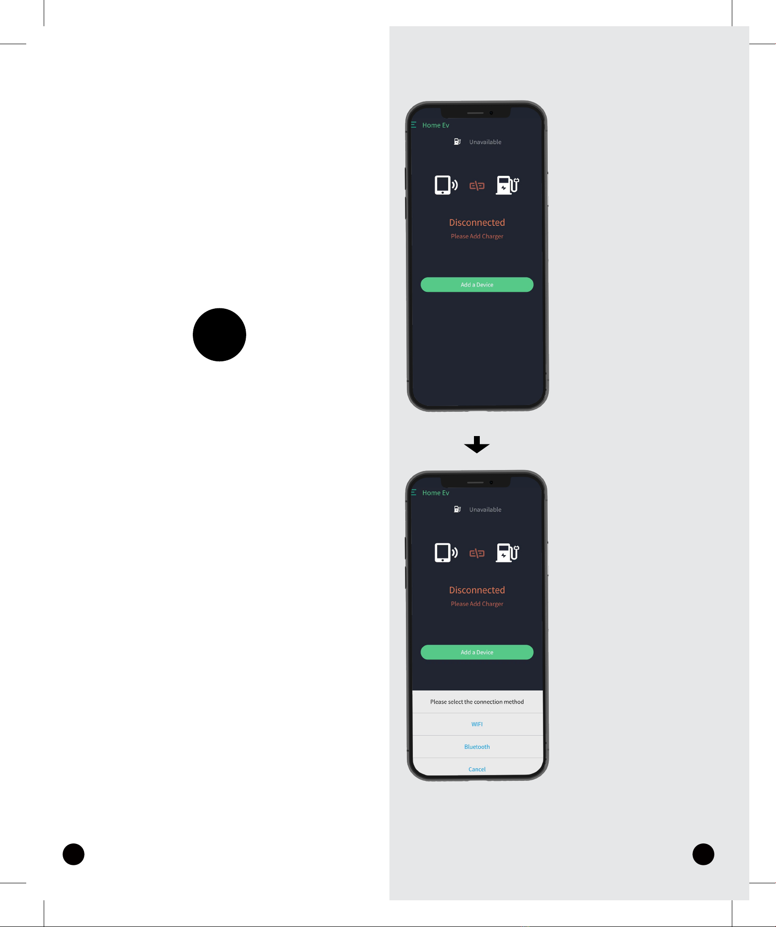
BLUETOOTH
CONNECT
01
1. Add a Device,enter
pairing mode
2. Turn on your phone's
Bluetooth and
select the Bluetooth
option

25 26
3.You can pull down to
refresh the bluetooth list,
and choose the
bluetooth name
consistent with the
charger’s SN
4.Select the appropriate
method (with scanning
code or automatic
identification input),
inputing the SN.
Note:
QR code on the side of
the charger
Connection complete
27 28
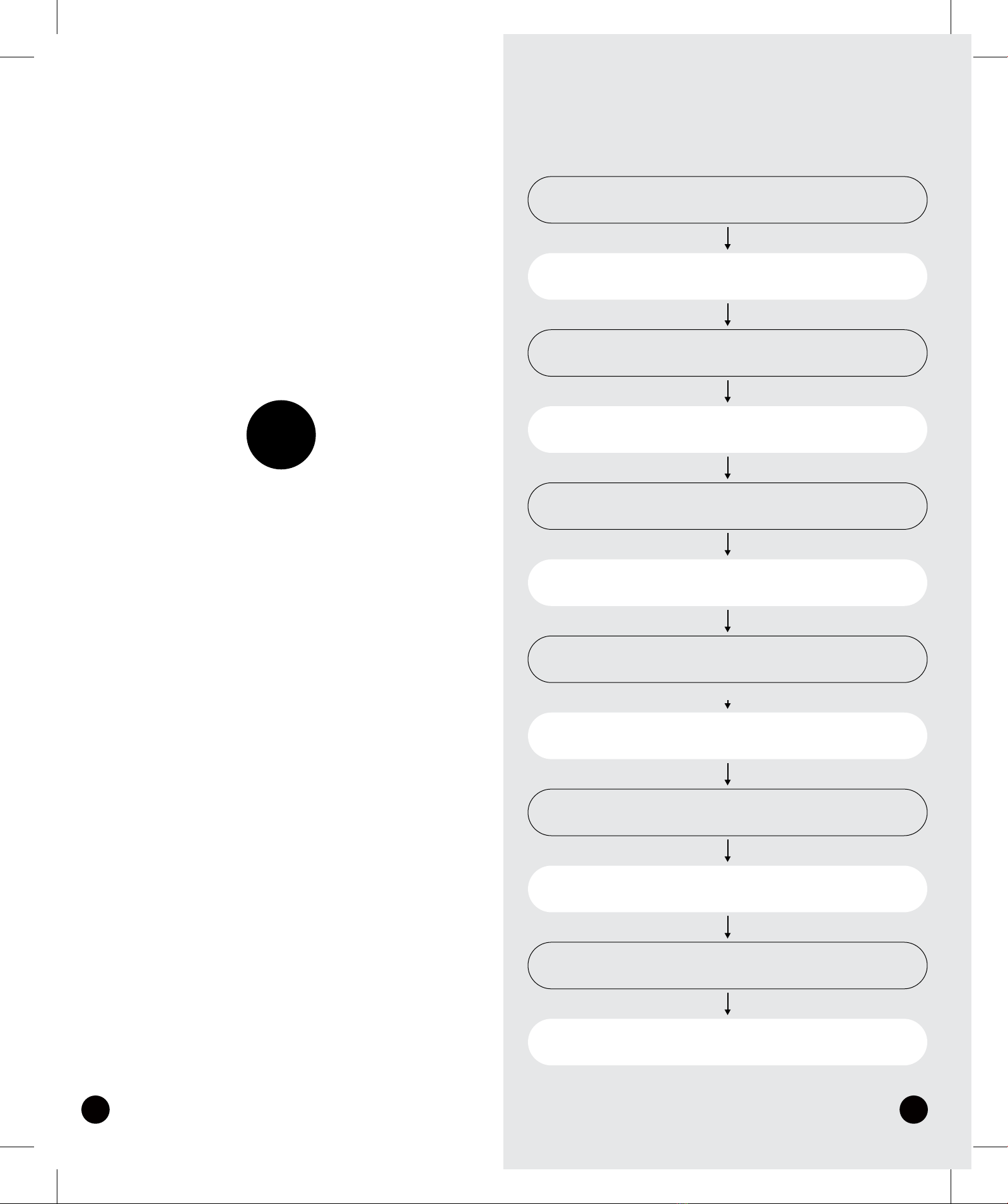
FIRST TIME
WIFI
CONFIGURATION
02
First time to configurate wifi
Add a Device
Turn on Bluetooth on phone
Select wifi
Input SN
Set your wifi account and password
setting complete
Restart the charger and App
wating 40 seconds
Add a Device
Select wifi
Waiting for connect complete
connect complete
Charging operation
29 30
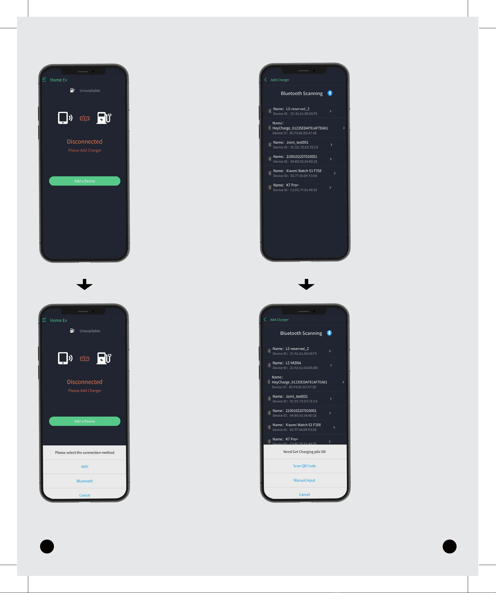
1.Add a Device
2.Turn on the bluetooth
on phone,then
select wifi
Note:
Using WIFI for the first
time, you need to use
Bluetooth to configure
the account for the
charger (when the
mobile phone and the
charger are connected
to the same WIFI, WIFI
control can be workable)
3. Pull down to refresh
the Bluetooth list, and
select the Bluetooth
name that is consistent
with the charger’s SN.
4.Select the appropriate
method (with scanning
code or automatic
identification input),
inputing the SN.
Note:
QR code on the side of
the charger
31 32
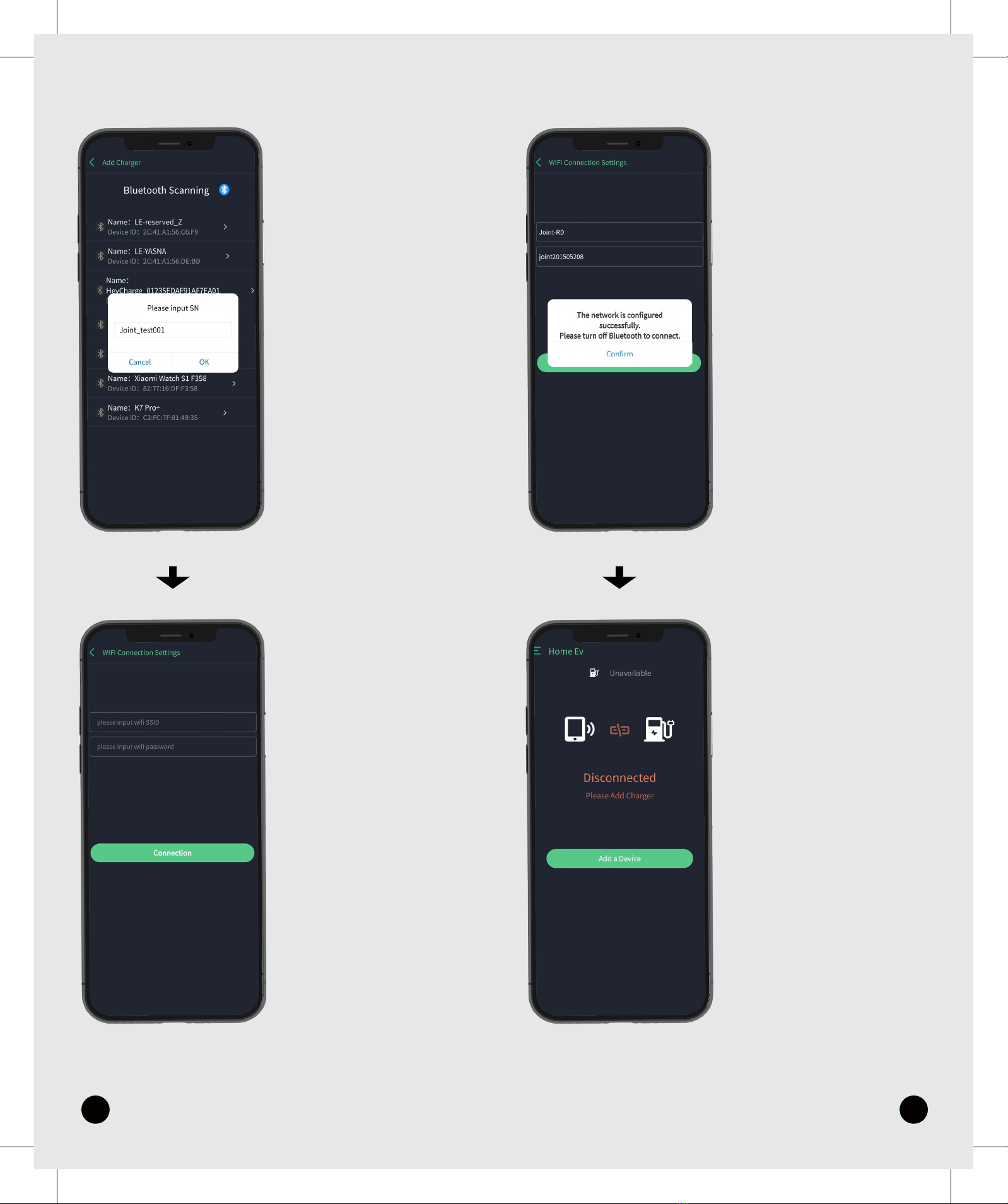
7.When it shows success-
ful configuration click
Confirm, then the app will
automatically log out.
8.Log in App again,when
the charger connect to
the wifi. Click Add a
Device.
Note:
After the configuration
complete, you need to
restart the charger,
waiting for about 40
seconds after restarting
and try to connect
5.Input SN to the wifi
configuration interface
6.Input wifi account and
password to connet

33
9.Select wifi
10.Connection complete
Note:
After the first
configuration, you
only need to click the
wifi to connect for
everytime usage.

HOME
www.thesparko.com
Table of contents


