8 9
ENEN Safety Information Safety Information
Cautions
Do not use private power generators as a power source for charging.
Incorrect installation and testing of the GLB+ Wallbox could potentially damage
either the vehicle’s Battery and/or the GLB+ Wallbox itself.
Do not operate the GLB+ Wallbox in temperatures outside its operating range –
see technical data.
Notes
All installation must be carried out by a qualified installer and comply with local
installation regulations.
Ensure that the GLB+ Wallbox’s charging cable is positioned so it will not be
stepped on, driven over, tripped over, or subjected to damage or stress.
Unroll the charging cable to prevent it from overheating.
Do not use cleaning solvents to clean any of the GLB+ Wallbox’s components.
The outside of the GLB+ Wallbox, the charging cable, and the end of the
charging cable should be periodically wiped with a clean, dry cloth to remove
accumulation of dirt and dust.
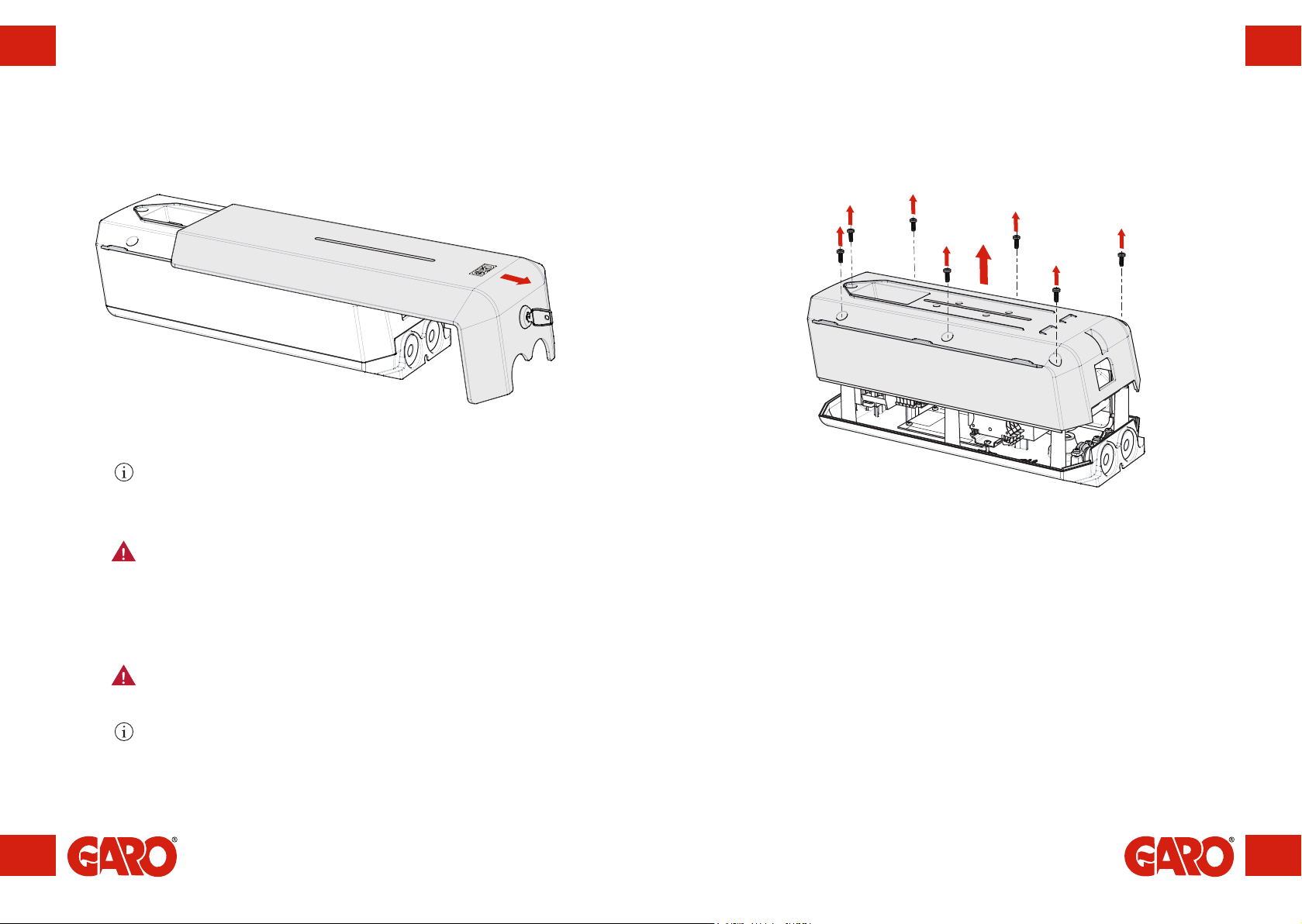
Be careful not to damage the circuit boards or components during installation.
Refer to local standards and regulations to ensure that charging current limits are
not exceeded.
The front cover must always be locked in its upper position in order to ensure
compliance with IP Code IP44.
Avoid mounting the wall box in direct sunlight. The charging current will be
reduced to 16A if the temperature limit inside the wallbox is exceeded. Charging
can also be completely turned off should the wallbox be too hot, this is a safety
feature to ensure a long life-time of the product.
To balance out the load, it is important to rotate the phases when connecting
several of GLB Wallbox to the same system. Note that 1-phase charging is
common in electric vehicles and L1 in the GLB+ is used for this purpose.
This product is already internally Dielectric Voltage Withstand Tested from
the factory. It is important not to connect the product when doing an external
Dielectric Voltage Withstand Test, since the product has electronics connected to
the PE.
To confirm that the GLB+ Wallbox is functioning correctly after installation, test
with an EVSE test box.