Spartan 81 User manual

SPARTAN
MODEL 81
Owner’s Manual
© 2020 Spartan Tool LLC
SPARTAN TOOL L.L.C.
8 0 0 . 4 3 5 . 3 8 6 6
www.spartantool.com
44298200 4-9-2020
Model 81
Record the Serial Number of your
and give the number to the factory
when ordering parts.
Serial
Number ...........................................

Page 2
Warning
―Read the safety and operating instructions before using any Spartan Tool products. Drain and
sewer cleaning can be dangerous if proper procedures are not followed and appropriate safety
gear is not utilized.
―Before starting unit, be sure to wear personal protective equipment such as safety goggles or face
shield and protective clothing such as gloves, coveralls or raincoat, rubber boots with metatarsal
guards, and hearing protection.
―Drains and sewer can carry bacteria and other infectious micro-organisms or materials which can
cause death or severe illness.Avoid exposing eyes, nose, mouth, ears, hands and cuts and abrasions
to waste water or other potentially infectious materials during drain and sewer cleaning operations.
To further help protect against exposure to infectious materials, wash hands, arms and other areas
of the body, as needed, with hot, soapy water and, if necessary, ush mucous membranes with
water. Also, disinfect potentially contaminated equipment by washing such surfaces with a hot
soapy wash using a strong detergent.
―For any questions contact the company at the address shown below.
“California Prop. 65: This product may contain an extremely small amount of lead in the coating.
Lead is a material known to the State of California to cause cancer or reproductive toxicity.”
SPARTAN TOOL L.L.C.
1618 Terminal Road
Niles, MI 49120
800.435.3866 ♦ Fax 888.876.2371
www.spartantool.com

Page 3
Table of Contents
OPERATING SECTION
Warning .................................................................................................................................... 2
Specications & Features ......................................................................................................... 4
How to Assemble ...................................................................................................................... 5
Operating Instructions .............................................................................................................. 5
How to Repair 1/4” and 5/16” Cables ....................................................................................... 6
Operating a Power Driven Cleaning Tool ................................................................................ 6
How to Install Cable in Model 81 ............................................................................................. 7
Safety Instructions ...............................................................................................................8-11
PARTS & ACCESSORIES SECTION
Model 81 Cables................................................................................................................. 12-13
Power Unit -04703300- ...................................................................................................... 14-15
Electrical Assembly -44002400- ............................................................................................. 16
Wiring Diagram ....................................................................................................................... 17
Air Bulb & Hose Assembly....................................................................................................... 17
Drum Assembly -04722600- ................................................................................................... 18
Warranty Information .............................................................................................................. 19

Page 4
Specications & Features
Specication:
Pipe sizes: .................................................................................................1-1/14" to 3" diameter
Weight ..............................................................................................................................35 lbs.
Cable capacity: .......................................................... 50 feet of 1/4 or 5/16 inch diameter cable
Size: ....................................................................................................... 18" W x 16" H x 16" D
Motor: ...........................................................................................................115 Volt / 1.85 Amp
RPM: ................................................................................................................................... 270
Features:
Compact and lightweight power for 1-1/4" to 3" lines up to 50'
Can be operated vertically or horizontally
Easy to handle and carry
Air-operateed foot switch
Quick interchangeable drum capabity
25' power cord with ground fault interupter
Unique cone-shaped internal drum applies extra torque to the cable

Page 5
How to Assemble
How to Assemble
Remove drum and power unit from cartons.
Step 1 Set power unit in vertical position. (See picture on front page)
Step 2 Mount drum on power unit. Lock drum to power unit by tightening (2) thumb screws. (Thumb
screw shoulder must enter hole in collar before tightening.)
Step 3 Loosen (3) wing nuts on motor mount plate. Put V-belt around pulley and drum. Move motor
mounting plate until V-belt is rm. If the belt is too tight, machine will not operate. Tighten (3) wing nuts.
1. Insert proper size of cable in machine. Use open hook cables in up to 1 1/2” lines, use 5/16” innercore
cable for 1 1/2” to 2” lines.
WE DO NOT RECOMMEND USING YOUR 1/4” CABLE IN LINES LARGER THAN 1 1/2” IN DIAMETER.
2. Place unit close to pipe opening (ideally 12” if possible).
3. Pull out enough cable to enter waste line or cross bar.
4. Position switch in Forward (F) position. Don’t reverse motor or use Reverse Action Switch until
machine comes to dead stop and then only to remove cable through cross bar.
5. Depress foot switch pedal, causing cable to rotate through cross bar or into pipe opening. (Forward
only).
6. Take 6” to 8” length of cable, and slowly feed it into the line giving the cable time to round ttings and
to remove stoppage.
7. When motor slows up, indicating a load on same, pull cable back a bit and start moving it forwards
and backwards. This reciprocating action keeps the cable rotating - keeps cable from getting “hung-
up” - the main cause of cable kinkage or breakage.
8. If cable gets “hung-up”, stop your machine and reverse the direction of same through Reverse Switch,
pulling back as you do so to free working end of cable.
WARNING: Do not use Reverse Switch until you motor unit comes to dead stop!
9. Repeat this action as often as necessary to clean the line.
10. When job is completed, feed all cable back into drum 6” to 8” at a time - DON’T take long bites.
11. You must reverse rotation of the drum to remove cable through a crossbar.
12. You may drain the drum of excess liquids by removing the drain plug which is the smaller hex bolt on
the back of the drum.

Page 6
How to Repair
1/4” and 5/16” Cables
Operating a Power
Driven Cleaning Tool
All 1/4” and 5/16” cables can be repaired with a replacable end. If you kink your cable, cut the cable o
at the kinked portion. Grind the end of same to provide a lead thread. Now, pick up your repair end and
thread same on the regular cable, as you would a nut on a bolt, turning same about three turns, which will
fasten it to the cable securely. Repair ends can be purchased at www.spartantool.com.
1. Stay close to pipe opening, (ideally 12” if possible) during operations especially when rounding
ttings or removing stoppage in lines.
2. Move your cable backwards and forwards constantly when you get into stoppage, thereby preventing
your cable from getting “hung-up”, causing unnecessary kinkage. Remember - a rotating cable cannot
kink or break. Kinkage of cable takes place only when the working end of the cable gets “hung-up”
and you keep on twisting the other end.
3. Don’t attempt to round ttings or remove stoppage until your drum reaches full speed. It is the rotation
of the cable that enables it to either (a) round ttings, or (b) remove stoppage - NOT push power.

Page 7
How to Install Cable
in Model 81
1. Position drum unit in a vertical position. Remove (6) nuts, washers, drum cover, drum cover spacer,
and (2) drum cover seals.
2. Assemble drum cover spacer and (2) seals to outer drum as required for various cables. See Figure
1 and Figure 2.
3. Insert cable through drum cover as illustrated in Figure 1.
4. Place end of cable in outer drum. Slide cable under clamp. Cable should enter clamp in counterclockwise
direction and extend approximately 1” beyond clamp. See Figure 1. tighten clamp screw.
5. Place drum cover on outer drum assembly and secure with (6) nuts and washers. Assemble all (6)
nuts, tightening all nuts a little at a time; about 3 times around. Then give nuts a nal tightening.
6. Feed remainder of cable into drum while drum is operating in forward only.
Fig 1 Fig 2
Page 8
Safety Instructions
Use of any electrical equipment in a wet or damp environment can cause fatal shock if not properly
guarded against by the operator.
1. Know Your Drain Cleaning Machine. Read this Operator’s Manual carefully. Learn the operation,
applications and limitations of this machine.
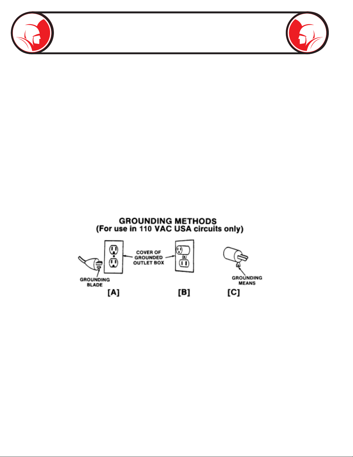
2. Grounding Instructions. Before using your Spartan equipment, make sure that a properly grounded,
(three hole) electrical outlet is available. If not, as in older homes, use a three-prong adapter and
connect the green pigtail or grounding lug to a known ground, such as a (metallic) cold water pipe.
This tool should be grounded while in use to protect the operator from electric shock. The tool is
equipped with a three-conductor cored and proper grounding type receptacle. The green (or green
and yellow) conductor in the cord is the grounding wire. Never connect this wire to a live terminal.
If your unit is for use on less than 150 volts, it has a plug that looks like that shown in Fig. 1A. An
adapter, (Fig. 1B and 1C), is available for connecting three-prong plugs to two-prong receptacles,
(except in Canada). If such an adapter is used, the green colored rigid ear, lug, or the like, extending
from the adapter must be connected to a permanent ground such as a properly grounded outlet box.
This machine is equipped with a Ground Fault Circuit Interrupter (GFCI), which should always be plugged
directly into an inspected, grounded receptacle. Plug the three-pronged plug on the machine power cored
with GFCI directly into an inspected grounded outlet and then test and reset the GFCI.
Never cut o the grounding prong on the power cord for use in a two-hole outlet. Doing so cuts o your
protection from shock. Replace or repair all damaged power cords and components.
Figure 1

Page 9
Safety Instructions (cont.)
3. Extension Cords. DANGER- Improper use of an extension cord will cause death or severe injury.
The GFCI on the machine’s power cord does not protect the operator from electrical shock along the
extension cord.
If an extension cord must be used, it must be of an approved, three-wire construction, equipped with
a three-pronged plug, and in good condition. Replace or repair damaged cords.
Do not use an undersized extension cord. An undersized cord will cause a drop in line voltage
resulting in loss of power and overheating. Use the following minimum gages depending upon the
length of the extension cord:
-16 Ga. –for cords of less than 100 feet in length
-14 Ga. –for cords of 100 feet to 150 feet in length.
If in doubt, use the next heavier gage. (The smaller the gage number, the heavier the cord.) When
the machine is used outdoors, use only extension cords intended for use outdoors and so marked.
Do not allow an extension cord to be exposed to water.
Don’t assume that all three hole outlets are properly installed. Check the outlet and also the adapter, if
used, with an outlet testing device which quickly indicates if a ground is connected. Correct a faulty test
indication before proceeding.
4. Don’t Abuse Cord. Never move or lift tool by cord or yank it to disconnect from receptacle. Keep cord
from heat, oil and sharp edges.
5. Disconnect Power Cord. When not in use, before servicing, and when changing accessories, such
as blades and cutters.
6. Guard Against Electric Shock. Prevent body contact with grounded surfaces such as pipes, radiators,
ranges, refrigerator enclosures.
7. Avoid Accidental Starting. Don’t move plugged-in tools. Make sure switch is in OFF position before
plugging in power cord.
8. Stay Alert. Watch what you are doing. Use common sense. Do not operate tool when you are tired.
9. Keep Work Area Clean. Cluttered areas invite injuries.
10. Consider Work Area Environment. Don’t expose power tools to rain. Keep work area well lit. Do not
use tool in presence of ammable liquids or gases. Avoid operating the machine in areas of standing
water.

Page 10
Safety Instructions (cont.)
11. Dress properly. Do not wear loose clothing or jewelry. They can be caught in moving parts. Wear
protective hair covering to contain long hair.
Wear standard equipment. (Spartan riveted gloves). Never grasp a rotating cable with a cloth or
loose tting glove which would get wrapped around cable. Replace gloves if rivets or staples start to
pull out.
Wear rubber boots and wear rubber gloves inside your Spartan cable handling gloves to further
insulate
12. Use Safety Glasses. Guard against foreign material that might y o cable.
13. Don’t Overreach. Keep proper footing and balance at all times.
14. Keep Children Away. Do not let visitors contact tool or extension cord. All visitors should be kept
away from work area.
15. Use Recommended Equipment and Accessories. Use of improper equipment may be hazardous.
Don’t force small cable with attachment to do the job of heavy-duty cable.
16. Don’t Force Tool. It will do the job better and safer at the rate for which it was intended.
17. Remove Punches and Wrenches. Form a habit of checking to see that punches and adjusting
wrenches are removed from tool before turning it on.
18. Keep Guards in Place. Never operate machine with guard removed.
19. Avoid Operating Machine in Reverse. Operating machine in reverse can result in cable damage and
is used only to back tool away from an obstruction. Warning! Continued drum rotation in reverse
position will cause cable to “jump” out of drum. Possible operator injury could result.
20. Do Not Over Torque Cables. Excessive and/or continued rotation of the drum once an obstruction
has been encountered will over torque the cable. Kinking or breakage of cable may result. A worn
cable can be identied as being very limber, kinked or as having attened coils on the outside of
cable. Worn cable should be replaced as soon as possible.

Page 11
Safety Instructions (cont.)
21. Maintain Tools with Care. Keep tools sharp and clean for better and safer performance.
Follow instructions for lubricating and changing accessories.
Never use damaged power cords.
Inspect tool cords periodically and if damaged, repair with proper Spartan replacement parts.
Inspect extension cords periodically and replace if damaged.
Keep handles dry, clean, and free from oil and grease.
22. Check Damaged Parts. Before further use of the tool, a guard or other part that is damaged should be
carefully checked to determine that it will operate properly and perform its intended function. Check
for alignment of moving parts, binding of moving parts, breakage of parts, mounting and any other
conditions that may aect its operation. A guard or other part that is damaged should be properly
repaired or replaced.
Replace defective switches with proper Spartan replacement parts.
Do not use tool if switch does not turn on and o.
23. Store Idle Tools. When not in use, tools should be stored in a dry and locked up place, away from
children.
24. Handling Cables. Be very careful when cleaning drains exposed to cleaning compounds. Wear
protective gloves when handling cable, and avoid direct contact of skin and especially the eyes and
facial areas as serious burns can result from some drain cleaning compounds.

Page 12
Model 81 Cables
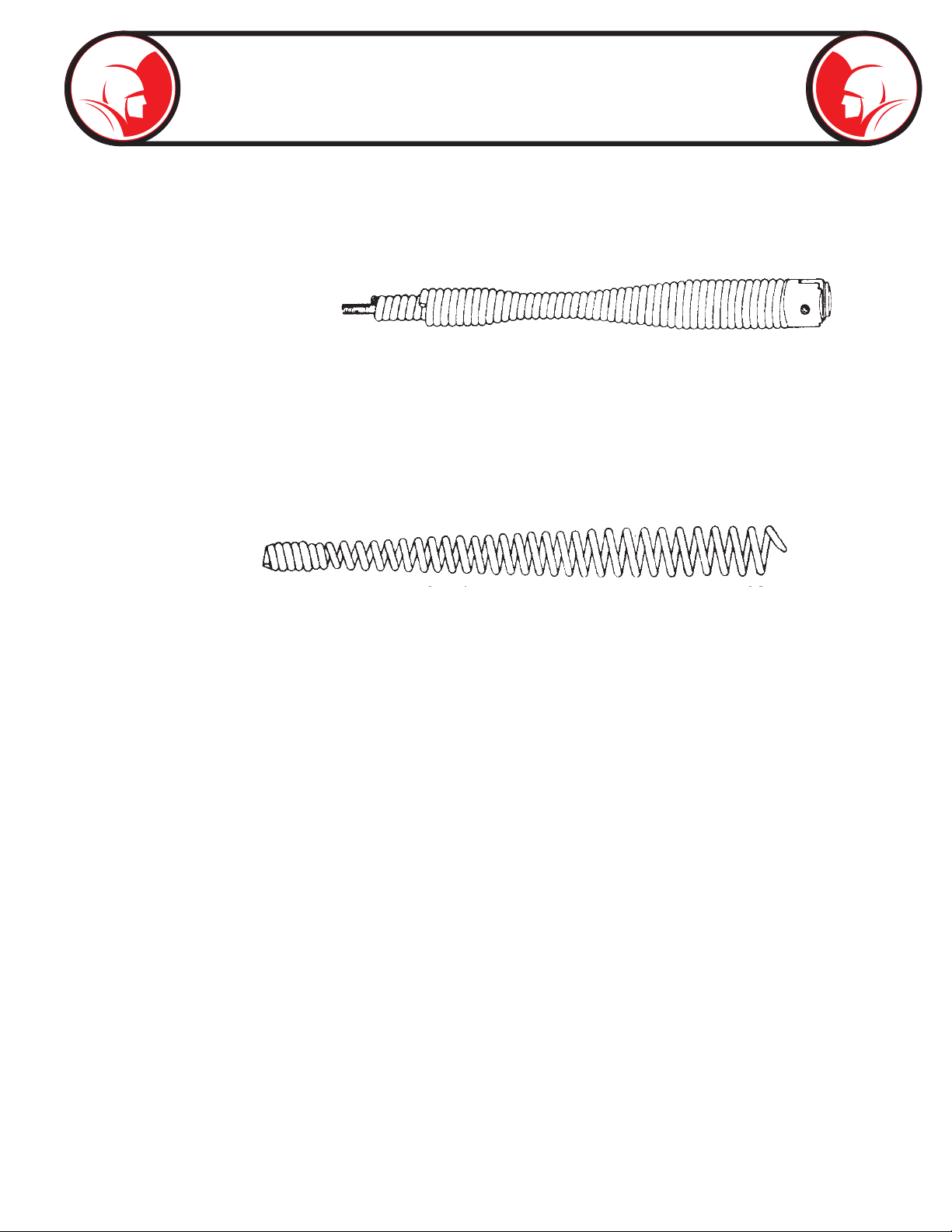
Spartan Cables Without Inner Core
Flexible open hook end enables operator to thread cable through cross bars - eliminating necessity of
removing trap - to do a thorough job quickly. One repair hook furnished with each cable.
1/4” Open Hook End Cable Designed for rodding 1 ¼” lines only.
04212101 1/4” x 15'
04212102 1/4” x 25'
04212103 1/4” x 30'
04212104 1/4” x 35'
04212105 1/4” x 50'
5/16" Open Hook End Cable Designed for rodding 1¼” to 1½” lines, such as those leading fromlavatories,
bath tubs, shower stalls.
04212402 5/16" x 25'
04212403 5/16" x 30'
04212404 5/16" x 35'
04212405 5/16" x 50'
Spartan Drop-Head Cable
44104301 1/4” x 25' (No Inner-Core)
44104302 1/4” x 35' (No Inner-Core)
03449002 5/16" x 25' (With Inner-Core)
03449003 5/16" x 30' (With Inner-Core)
03449004 5/16" x 35' (With Inner-Core)
03449005 5/16" x 50' (With Inner-Core)
5/16" Multi-Purpose Inner-Core Cable. Designed for rodding 1¼” to 1½” lavatory, sink line waste and for
light duty in 2" lines.
Parts For 5/16" Inner-Core Cable:
02867200 Blade, ¾”Wide 02882200 Expansion Pin ¼” x 5/8"
02867300 Blade, 1" Wide 02827700 Allen Key for Blades
02781100 Drop Head Assembly 02827400 Socket Set Screw for Blades
02814700 Bag of parts for 5/16" including
drop head
Page 13
Model 81 Cables (cont.)
Repair Bulbs
For 5/16" Inner-Core Cables:
02885200 Repair Bulb
Repair Hooks
How to Use Repair Hook or Repair Bulbs
If cable is kinked, simply remove kinked portion by cutting it o at a point about 1" back of bent section.
Attach Repair Hook by threading it over cable end about four turns.
02789700 for 1/4” Cable Right Hand Wound
02789800 for 5/16" Cable Right Hand Wound

Page 14
Power Unit
-04703300-
2
7
12
13
19
22
4
22
8
22
14
15
8
8
22
20
10
11
21
16
15
5
3
8
239
24
3
6
24
25
27
26
26
18
17
5
17
18
24
6
23 6
11
8
8
9
21
10
1
5
5
15
5
3
16
25
12

Page 15
Power Unit
-04703300-
17
18
24
6
23 6
11
8
8
9
21
10
1
5
5
15
5
3
16
25
12
ELEVATOR BOLT 1/4-20 X 2-1/2
44307320
1
27
ELEVATOR BOLT 1/4-20 X 1-3/4
44307310226
GUARD, MOD 81 BELT44307300
1
25
81 ELECTRICAL ASSEMBLY44002400
1
24
COVER, CONTROL BOX (MODEL 81)
44002100
1
23
NUT, ACORN 10-3204725200
4
22
GRIP, MODEL 81 HANDLE04715200
1
21
LABEL, SWITCH DIRECTION
04714900
1
20
DECAL, 81 BELT COVER04703600
1
19
WELDMENT, MODEL 81 FRAME04702810
1
18
MOTOR, MODEL 81 (included in 44002400 assembly)
04702401
117
PLATE, MOTOR MOUNTING04702200
1
16
SPACER, 3/8 OD X 1/4 ID X 5/8
04700700
115
SHEAVE, MODEL 8104700600
114
BEARING, FLANGED 1/2 ID X 3/4 OD
04700400
1
13
COLLAR, SHAFT (MODEL 81)
04700300
1
12
MOUNTING TIP, RUBBER04699810
411
V-BELT, MODEL 8104233200
1
10
DECAL, WARNING04220200
1
9
NUT, HEX KEP 10-3203850100
5
8
BRONZE BRG MDL-8103421300
17
SCREW, SHEET METAL #6 X 1/4
0339440026
WASHER, FLAT 5/16 USS
02899200
45
DECAL, EASY-LIFT02830900
14
SCREW, MACHINE 10-32 X 3/8
0282380033
RETAINING RING- SMALL
02822500
1
2
NUT, WING 1/4-20
001405003
1
DESCRIPTION
PART NUMBER
QTY
ITEM

Page 16
Electrical Assembly
- 44002400 -
17
18
1
49
2
19
5
6
7
21
KEYWAY FACING ("F") FORWARD ON
CONTROL BOX
18
9
15
13
22
23
10
20
22
22
3
12
11
14
8
8
16
CONNECTOR-PUSH-ON 2 WIRE79925700
1
23
TERMINAL, NYLON SELF-INSULATED77807800322
POWER (12GA) CORD 25' W/GFI
71103300
1
21
LOCKNUT, WATER SEAL 1/2 TRADE SIZE
44227605220
LOCKNUT, 1/2 TRADE SIZE
442276002
19
CORD GRIP, 1/2 ALUM STRT. .375
44227500218
ASSY AIR FT SWTCH TRANSMIT
44225800
117
DISCONNECT, .250 FEMALE 16-1444216100
1
16
ASSY, WIRE JUMPER BLACK 5"
44003000
115
ASSY, PRESSURE SWITCH (WM)
44002800
114
WELDMENT, MODEL 81 CONTROL BOX44002200
1
13
TERMINAL, FLAG SILP ON06517743
1
12
MOTOR, MODEL 8104702401
111
CLAMP, STEPLESS EAR 1/2
04652700
1
10
JUMPER WIRE16GA YELLOW 5"
04234400
1
9
JUMPER WIRE16GA BLACK 2"
0423400038
CLAMP, CAPACITOR04230900
1
7
CAP, RUBBER (CAPACITOR)
04230000
1
6
CAPACITOR04229900
15
SWITCH, TOGGLE04225800
1
4
TERMINAL, SPADE MVU-14-250-DFK03447200
1
3
NUT, KEP #8-32 ZINC PLATED03312001
1
2
SCREW, MACHINE SLOTTED 8-32 X 1/2
01921801
11
DESCRIPTION
PART NUMBER
QTY
ITEM

Page 17
17
18
1
49
2
19
5
6
7
21
KEYWAY FACING ("F") FORWARD ON
CONTROL BOX
18
9
15
13
22
23
10
20
22
22
3
12
11
14
8
8
16
Wiring Diagram
Air Bulb Transmitter
44225800
ITEM# PART # NUMBER DESCRIPTION
1 1 44003000 Jumper Wire (Black)
2 1 04234400 Jumper Wire (Yellow)
ITEM# PART # NUMBER DESCRIPTION
1 1 04576900 Pressure Transmitter
2 1 04577100 Air Hose, 8'
3 2 04652700 Hose Clamp
` ^m^` fqlo
MOTOR
t efqb
RED
t efqb
BLUE
BLACK
dobbk
mobpprob=ptfq`e
W
= E
= =
_i^`h
ml i^ofqv
fa bk qfc f` ^qfl k
dobbk
TOGGLE SWITCH
2
CONNECTOR-PUSH-ON 2 WIRE79925700
1
23
TERMINAL, NYLON SELF-INSULATED77807800322
POWER (12GA) CORD 25' W/GFI
71103300
1
21
LOCKNUT, WATER SEAL 1/2 TRADE SIZE
44227605220
LOCKNUT, 1/2 TRADE SIZE
442276002
19
CORD GRIP, 1/2 ALUM STRT. .375
44227500218
ASSY AIR FT SWTCH TRANSMIT
44225800
117
DISCONNECT, .250 FEMALE 16-1444216100
1
16
ASSY, WIRE JUMPER BLACK 5"
44003000
115
ASSY, PRESSURE SWITCH (WM)
44002800
114
WELDMENT, MODEL 81 CONTROL BOX44002200
1
13
TERMINAL, FLAG SILP ON06517743
1
12
MOTOR, MODEL 8104702401
111
CLAMP, STEPLESS EAR 1/2
04652700
1
10
JUMPER WIRE16GA YELLOW 5"
04234400
1
9
JUMPER WIRE16GA BLACK 2"
0423400038
CLAMP, CAPACITOR04230900
1
7
CAP, RUBBER (CAPACITOR)
04230000
1
6
CAPACITOR04229900
15
SWITCH, TOGGLE04225800
1
4
TERMINAL, SPADE MVU-14-250-DFK03447200
1
3
NUT, KEP #8-32 ZINC PLATED03312001
1
2
SCREW, MACHINE SLOTTED 8-32 X 1/2
01921801
11
DESCRIPTION
PART NUMBER
QTY
ITEM
ORANGE3 6
YELLOW
BLACK
BLACK WHITE
PRESSURE SWITCH
POLARITY
IDENTIFICATION CAPACITOR
GREEN
WHITE
GREEN
NOTE:
KEYWAY
FACING FORWARD (F)
ON CONTROL BOX
1 4 7
2 5 8
9
1
2
3
2
1

Page 18
Drum Assembly
- 04722600 -
ITEM# PART # NUMBER DESCRIPTION
1 1 04726900 81 Outer D rum & Flange
2 1 04727000 81 D rum C over
3 1 04720400 Drum C over Spacer
4 2 04720300 Drum C over Seal
5 1 44280500 81 C able C lamp Assembly
6 2 04701400 Thumb Screw
76 01588200 Flat W asher, #10
8 6 04725200 Acorn Nut, #10-32
9 1 02939000 Hex Head Screw, 5 /16-18 x 5 /16
10 1 02825100 Flat W asher, 1/4
11 104707700 Nylon C ollar
12 1 04728200 Hex Head S crew, 1 /4-20 x 3/8
13 1 04233800 Pop Rivet, 1/8
14 1 04714700 Spartan D rum D ecal
15 1 04714800 Warning D ecal

Page 19
Warranty Information
ONE YEAR WARRANTY
Spartan Tool warrants its equipment to free from defects in material and workmanship for one year
from the date of purchase. To obtain warranty service, a purchaser should notify Spartan Tool in
writing, at the address provided below, within the warranty period, and Spartan Tool will direct where
to take or send the equipment for service. If the defect is covered by the warranty, Spartan Tool
will repair or replace, at its option, the defective equipment, without charge for labor or materials.
(Freight and insurance are the purchaser’s responsibility.)
This warranty is limited to the original retail purchaser and is not transferable. Spartan Tool assumes
no responsibility for damage due to accident, neglect, abuse, tampering or misuse, nor damage from
repairs or alterations by others. This warranty does not cover damage to the equipment resulting
from the use of replacement parts other than Spartan Tool parts.
Spartan Tool’s sole obligation and the original retail purchaser’s exclusive remedy under this warranty
shall be for repair or replacement as described above. ALL OTHER WARRANTIES, WHETHER
EXPRESSED OR IMPLIED, INCLUDING BUT NOT LIMITED TO IMPLIED WARRANTIES OF
MERCHANTABILITY AND FITNESS FOR A PARTICULAR PURPOSE ARE DISCLAIMED. IN
NO EVENT SHALL SPARTAN TOOL BE LIABLE FOR ANY INCIDENTAL OR CONSEQUENTIAL
DAMAGES.
SPARTAN TOOL L.L.C.
Niles, Michigan 49120
Spartan Tool L.L.C. reserves the right to make changes at any time, without notice, to specications
and models and also discontinue models. The right is also reserved to change specications or
parts at any time without incurring any obligation to equip same on models manufactured prior to
the date of change.
SPARTAN TOOL L.L.C.
1618 Terminal Road
Niles, MI 49120
800.435.3866 ♦ Fax 888.876.2371
www.spartantool.com
Other manuals for 81
1
Table of contents
Other Spartan Pipe Cleaner manuals


