StoneAge BADGER BA-LKD-P4 User manual
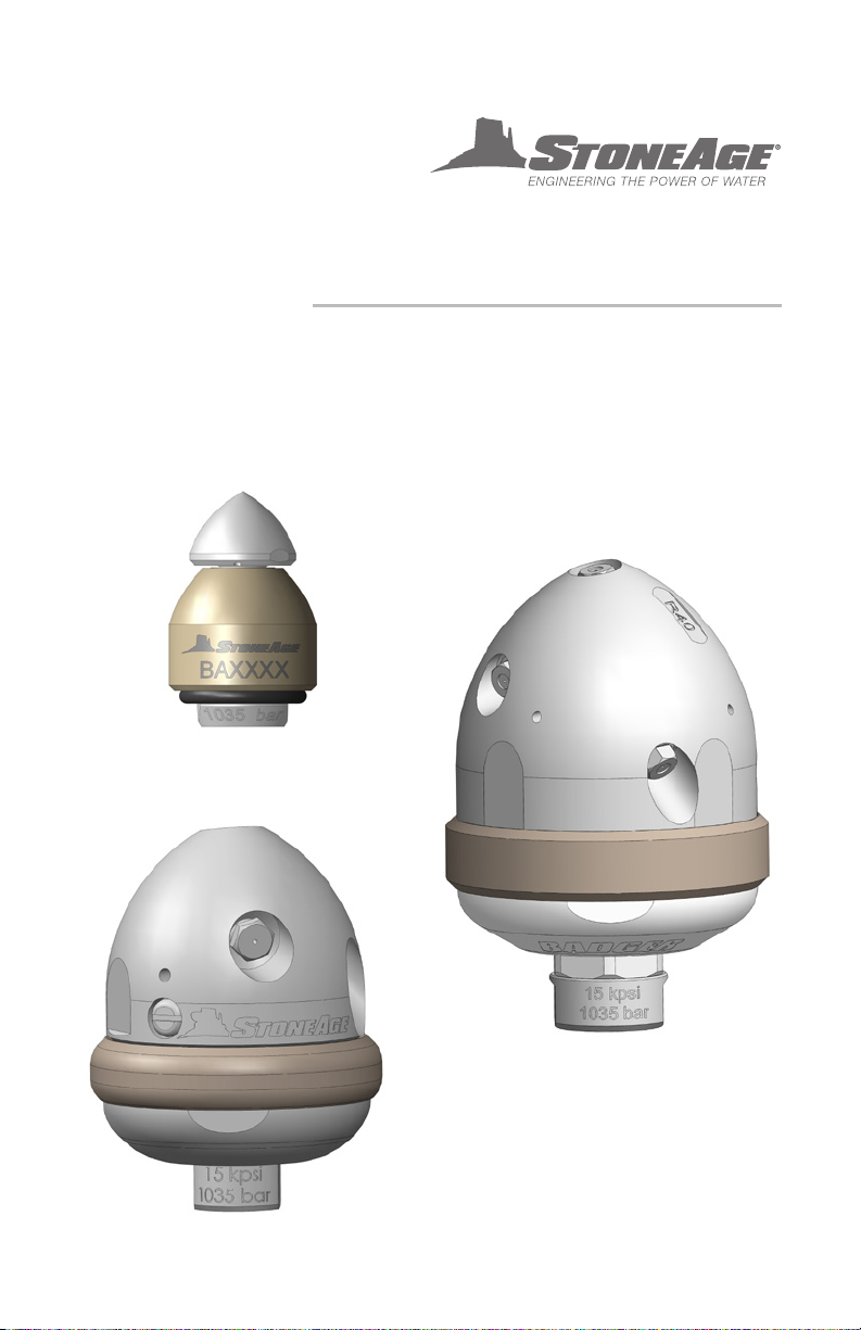
BADGER FAMILY
SELF ROTARY SWIVELS
USER MANUAL
*EXCLUDES BA-H6 4” 40K MODEL
2 INCH
4 INCH
6 INCH
PL 663 REV P
(06/2020)

866-795-1586 • WWW.STONEAGETOOLS.COM
2
This manual must be used in accordance with all applicable national laws. The manual shall be
regarded as a part of the machine and shall be kept for reference until the nal dismantling of the
machine, as dened by applicable national law(s). Updated manuals can be downloaded at:
https://www.stoneagetools.com/manuals
MANUFACTURER’S INFORMATION ...........................................................3
SPECIFICATIONS FOR ALL MODELS .....................................................3
FEATURES FOR ALL MODELS ............................................................3
WARNING AND SAFETY INSTRUCTIONS .....................................................4
OPERATOR TRAINING, RISK ASSESSMENT, PPE ........................................4
PRE-RUN SAFETY CHECK ................................................................5
2” BADGER ....................................................................................6
MODEL AND HEAD INFORMATION .......................................................6
BACKOUT PREVENTION ..................................................................7
OPERATION AND TROUBLESHOOTING ..................................................8
HEAD REPLACEMENT INFORMATION ....................................................9
ASSEMBLY AND PARTS...................................................................11
4” BADGER ....................................................................................12
MODEL AND HEAD INFORMATION .......................................................12
BACKOUT PREVENTION ..................................................................13
OPERATION AND TROUBLESHOOTING ..................................................14
TOOL SERVICE AND VISCOUS FLUID INFORMATION ....................................15
DISASSEMBLY ............................................................................16
ASSEMBLY ................................................................................18
PART NUMBERS AND SERVICE KITS.....................................................20
6” BADGER ....................................................................................21
MODEL AND HEAD INFORMATION .......................................................21
BACKOUT PREVENTION ..................................................................22
OPERATION AND TROUBLESHOOTING ..................................................23
SPEED CONTROL ADJUSTMENT .........................................................24
TOOL SERVICE AND VISCOUS FLUID INFORMATION ....................................25
DISASSEMBLY ............................................................................26
ASSEMBLY ................................................................................28
PART NUMBERS AND SERVICE KITS.....................................................30
TERMS AND CONDITIONS AND WARRANTY ...........................................32
TABLE OF CONTENTS

866-795-1586 • WWW.STONEAGETOOLS.COM 3
StoneAge Inc.
466 S. Skylane Drive
Durango, CO 81303, USA
Phone: 970-259-2869
Toll Free: 866-795-1586
www.stoneagetools.com
StoneAge NL
Reedijk 7Q
3274 KE Heinenoord
Netherlands
(+31) (0) 85 902 73 70
Badger Model Specifications
Tool
Size
Tool Model
Number Pressure Range Flow Range
Inlet
Connection Weight Rotation Speed
Max Water
Temperature
2”
BA-LKD-P4
BA-LKD-BSPP4
8–15k psi
552–1034 bar
7-16 gpm
26–61 LPM
1/4 NPT
or
1/4 BSPP
0.45 lb
0.20 kg High Speed 250 ºF
120 ºC
BA-LKD-MP6R
BA-LKD-MP9L
BA-LKD-MP9R
15–22k psi
1034–1500bar
9.5 -18.5 gpm
36–70 LPM
3/8 MP
or
9/16 MP
0.45 lb
0.20 kg High Speed 250 ºF
120 ºC
4”
BAE-P6 5–15k psi
345 –1035 bar
12–35 gpm
45-132 LPM 3/8 NPT 3.0 lbs
1.4 kg
20-100 rpm (Slow Fluid)
75-250 rpm (Fast Fluid)
250 ºF
120 ºC
BAE-BSPP6
BAE-MP9L
BAE-MP9R
BAE-M24
5–22k psi
345–1500bar
12–34 gpm
45–130 LPM
3/8 BSPP
9/16 MP
M24
3.0 lbs
1.4 kg
20–100 rpm (Slow Fluid)
75–250 rpm (Fast Fluid)
250 ºF
120 ºC
BA-H6
(Not included in
this manual)
44k psi
3000 bar
4.5–12 gpm
17– 45.5 LPM
3/8 HP
Female
4.0 lbs
1.8 kg 100–400 rpm 250 ºF
120 ºC
6”
BA-MP9
BA-M24
12–22k psi
840 –1500 bar
14–43 gpm
53–163 LPM
9/16 MP
or
M24
8.0 lbs
3.6 kg
50–300 rpm
(Adjustable)
250 ºF
120 ºC
BA-P8 2–15k psi
140–1000 bar
15–55 gpm
57–208 LPM 1/2 NPT 8.0 lbs
3.6 kg
50–300 rpm
(Adjustable)
250 ºF
120 ºC
Badger Model Features
2”
• The only self-rotary tool on the market that can navigate 2 in. (50 mm) lines with bends and comes with head
locking technology for increased safety
• Head options allow the tool to be optimized for a variety of pump pressures and ows - unplug, polish, or
run longer lines based on jetting
• Optional fairing available to streamline tool during retrieval
4”
• Different jetting congurations allow for more or less pull and forward hitting power
• Navigates elbows as small as 4 in. (102 mm) at up to 22k psi (1500 bar)
• Self-rotary, speed controlled head provides complete internal coverage with optimum jet delivery
• Two speeds to choose from to maximize cleaning by choosing slower speeds for hard to clean or plugged
lines, and faster speeds for polishing easy to clean lines with a single tool
• Multiple jetting options optimize the tool for a variety of pumps pressures and ows - unplug, polish, or run
longer lines based on jetting
• Designed to easily pair with the AutoBox ABX-500 or ABX-PRO hose tractors for hands-free line cleaning.
6”
• Features adjustable speed control for ne-tuning to specic requirements
• Different jetting congurations allow for more or less pull and forward hitting power and optimize the tool for
a variety of pumps pressures and ows.
• Navigates elbows as small as 6 in. (152 mm)
• Speed controlled rotary tools provide complete internal coverage with optimum jet delivery
• Maximize cleaning by choosing slower speeds for hard to clean or plugged lines, and faster speeds for
polishing easy to clean lines with a single tool
• Centralizer options for larger line sizes available
• Designed to easily pair with the AutoBox ABX-500 or ABX-PRO hose tractors for hands-free line cleaning.
MANUFACTURER’S INFORMATION

866-795-1586 • WWW.STONEAGETOOLS.COM
4
PERSONAL PROTECTIVE EQUIPMENT
REQUIREMENTS
Use of Personal Protective Equipment (PPE) is
dependent on the working pressure of water and
the cleaning application. Managers, Supervisors,
and Operators MUST carry out a job specic risk
assessment to dene the exact requirements for
PPE. See Protective Equipment for Personnel
(Section 6) of WJTA-IMCA’s Recommended
Practices For The Use Of High-pressure
Waterjetting Equipment for additional information.
Hygiene - Operators are advised to wash
thoroughly after all waterjetting operations to
remove any waterblast residue which may contain
traces of harmful substances.
First aid provision - users MUST be provided with
suitable rst aid facilities at the operation site.
PPE may include:
• Eye protection: Full face visor
• Foot protection: Kevlar® brand or steel toe
capped, waterproof, non-slip safety boots
• Hand protection: Waterproof gloves
• Ear protection: Ear protection for a minimum
of 85 dBA
• Head protection: Hard hat that accepts a full
face visor and ear protection
• Body protection: Multi-layer waterproof
clothing approved for waterjetting
• Hose protection: Hose shroud
• Respiratory protection: May be required;
refer to job specic risk assessment
StoneAge has designed and manufactured this
equipment considering all hazards associated
with its operation. StoneAge assessed these risks
and incorporated safety features in the design.
StoneAge WILL NOT accept responsibility for the
results of misuse.
IT IS THE RESPONSIBILITY OF THE INSTALLER/
OPERATOR to conduct a job specic risk
assessment prior to use. Job specic risk
assessment MUST be repeated for each different
set up, material, and location.
The risk assessment MUST conform to the Health
and Safety at Work Act 1974 and other relevant
Health and Safety legislation.
The risk assessment MUST consider potential
material or substance hazards including:
• Aerosols
• Biological and microbiological (viral or
bacterial) agents
• Combustible materials
• Dusts
• Explosion
• Fibers
• Flammable substances
• Fluids
• Fumes
• Gases
• Mists
• Oxidizing Agents
OPERATOR TRAINING
Managers, Supervisors, and Operators MUST be
trained in Health and Safety Awareness of High-
pressure Water Jetting and hold a copy the Water
Jetting Association (WJA) Code of Practice, or
equivalent (see www.waterjetting.org.uk).
Operators MUST be trained to identify and
understand all applicable standards for the
equipment supplied. Operators should be trained
in manual handling techniques to prevent bodily
injury.
Operators MUST read, understand, and follow the
Operational and Training Requirements (Section
7.0) of WJTA-IMCA’s Recommended Practices For
The Use Of High-pressure Waterjetting Equipment,
or equivalent.
Operators MUST read, understand and follow
the Warnings, Safety Information, Assembly,
Installation, Connection, Operation, Transport,
Handling, Storage, and Maintenance Instructions
detailed in this manual.
WARNING AND SAFETY INSTRUCTIONS

866-795-1586 • WWW.STONEAGETOOLS.COM 5
WARNING
Operations with this equipment can be potentially
hazardous. Caution MUST be exercised prior
to and during equipment and water jet tool use.
Please read and follow all of these instructions,
in addition to the guidelines in the WJTA
Recommended Practices handbook, available
online at www.wjta.org. Deviating from safety
instructions and recommended practices can lead
to severe injury and/or death.
• Do not exceed the maximum operating
pressure specied for any component in a
system.
• The immediate work area MUST be marked
off to keep out untrained persons.
• Inspect the equipment for visible signs
of deterioration, damage, and improper
assembly. Do not operate if damaged, until
repaired.
• Make sure all threaded connections are tight
and free of leaks.
• Users of all Badger Tools
MUST be
trained and/or experienced in the use and
application of high-pressure technology
and cleaning, as well as all associated
safety measures, according to the WJTA
Recommended Practices for the use of
High-pressure Waterjetting Equipment.
• Install mechanical stops, stingers and back
out preventers as appropriate when doing any
tube, line or vessel cleaning.
• Always de-energize the system before
servicing or replacing any parts. Failure to do
so can result in severe injury and/or death.
PRE-RUN SAFETY CHECK
Refer to WJTA-IMCA’s, Recommended Practices
For The Use Of High-pressure Waterjetting
Equipment and/or The Water Jetting Association’s,
WJA Code of Practice for additional safety
information.
• Complete a job specic risk assessment and
act on the resulting actions.
• Adhere to all site specic safety procedures.
• Ensure the waterblasting zone is properly
barricaded and that warning signs are posted.
• Ensure the workplace is free of unnecessary
objects (e.g. loose parts, hoses, tools).
• Ensure all Operators are using the correct
Personal Protective Equipment (PPE).
• Check that the air hoses are properly
connected and tight.
• Check all hoses and accessories for damage
prior to use. Do not use damaged items. Only
high quality hoses intended for waterblast
applications should be used as high-pressure
hoses.
• Check all high-pressure threaded connections
for tightness.
• Operate the high-pressure water at full
pressure and use the Pneumatic Foot Pedal
Dump Control to verify that the dump valve is
working properly.
• Ensure that Operators never connect,
disconnect, or tighten hoses, adapters, or
accessories with the high-pressure water
pump unit running.
• Ensure no personnel are in the hydroblasting
zone.
WARNING AND SAFETY INSTRUCTIONS
866-795-1586 • WWW.STONEAGETOOLS.COM
6
2” BADGER MODEL AND HEAD INFORMATION
2” BADGER MODELS
The BA-LKD-P4 / BA-LKD-BSPP4 / BA-LKD-MP6R / BA-LKD-MP9L /
BA-LKD-MP9R are self-rotating swivels designed for cleaning 2” to 4”
tubes and lines with bends and long radius elbows, such as U-Tubes
and process lines.
The P4 and BSPP4 tools can be used at operating pressures up to
15,000 psi (1035 bar) and have either a 1/4”NPT or 1/4”BSPP female
pipe thread inlet.
The MP6R, MP9L and MP9R tools at up to 22,000 psi (1500 bar). The
MP6R tool has a 3/8” female right-hand medium pressure inlet. The
MP9L tool has a 9/16” female left-hand medium pressure inlet and
the MP9R has a 9/16” female right-hand medium pressure inlet.
The tools do not use any bearings, seals, or lubricating uid.
Rotation is powered by the jet thrust.
If a standard 1/4” NPT or BSPP hose end is used, they can pass
through elbows in 3” and larger lines. If using the tool in 2” line a
special shorter hose end is required to allow tool to travel through
elbows. Contact StoneAge for more information on the hose
requirements.
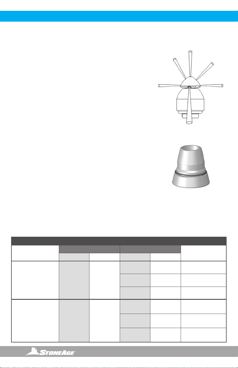
An OPTIONAL BA 530 Fairing Assembly is available for all 2” Badger
models when using hose sizes up to 6mm. The fairing is designed to
be attached to the back of the 2” Badger to help prevent the rear edge
of the tool from getting caught on obstructions during withdrawal from
tubes or lines. BA 530 Fairing
7 Ports:
1 @ 15º
1 @ 30º
1 @ 45º
2 @ 90º
2 @ 132º
15º
30º 45º
90º90º
2 x 132º
Port Locations
2” BADGER BACKOUT PREVENTION
2” BADGER HEAD CHART
MODEL / INLET
CONNECTIONS
PRESSURE RANGE FLOW RANGE BA 546-LKD-X
HEAD
psi bar gpm lpm
BA-LKD-P4
1/4 NPT
BA-LKD-BSPP4
1/4 BSPP
8-15K 552-1034
11-16 42-61 A
9-12.5 34-47 B
7-9.5 26-36 C
BA-LKD-MP6R
3/8 MP RIGHT
BA-LKD-MP9L
9/16 MP LEFT
BA-LKD-MP9R
9/16 MPRIGHT
15-22K 1034-1500
16-18.5 61-70 A
12.5-14.5 47-55 B
9.5-11 36-42 C
DETERMINING HEAD TYPE:
Three different universal head options can meet different pressure and ow congurations. The drilled
heads eliminate the need for replacing jet inserts. Operators can swap the drilled heads quickly to meet
the unique demands of each job. Specication assistance is available through one of our StoneAge
customer service reps at 1-866-795-1586. Or on line at www.stoneagetools.com
The chart below is calculated with hose pressure loss from 50 feet of 6 mm or ¼” ex lance.

866-795-1586 • WWW.STONEAGETOOLS.COM 7
DANGER
If the 2” BADGER is being used in lines larger than 4 inch diameter, a rigid stinger should be installed
between the tool inlet and the hose end; otherwise the tool can turn around and come back toward the
operator, causing serious injury or death.
Operations with this equipment can be potentially hazardous. Caution must be exercised prior to and
during machine and water jet tool use. Please read and follow all of these instructions, in addition to the
guidelines in the WJTA Recommended Practices handbook, available online at www.wjta.org.
Deviating from safety instructions and recommended practices can lead to severe injury and/or death.
2” BADGER BACKOUT PREVENTION
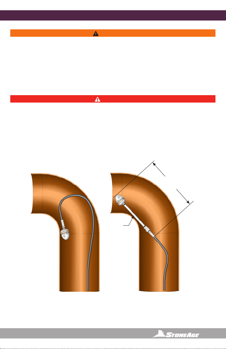
WARNING
Because of the short length of the Badger, the tool can turn around in large lines and come back at the
operator at a high rate of speed. If cleaning larger lines, a rigid “stinger” should be used between the
hose and the tool. It is recommended that the rigid length of the tool including hose end is 1-1/2 times
the inside diameter of the line being cleaned (see below).
Make sure there is an operator controlled dump in the system, operated by the person closest to the
cleaning job. The StoneAge ABX-500 and ABX-PRO Hose Tractors can be used to achieve safe and
consistent feed rates for line cleaning.
Follow all operating instructions in this manual.
1-1/2 times
line ID
Rigid
Stinger
IMPROPER USE:
Badger will turn around in
large diameter line
VERY DANGEROUS!
PROPER USE:
Badger with rigid “stinger”
to prevent turnaround, still
able to pass through elbows.
866-795-1586 • WWW.STONEAGETOOLS.COM
8
2” BADGER OPERATION AND TROUBLESHOOTING
OPERATION
1. Make sure the operator has a controlled
dump in the system and it is operated by
the person closest to the job. Test the dump
prior to beginning the job.
2. Flush out the high pressure hoses before
connecting the Badger to eliminate debris.
3. Attach tool to the end of the hose. Use
Parker Thread Mate and Teon tape on all
pipe thread connections (P4, BSPP4); use
anti-seize on all straight thread connections
(MP6R, MP9L, MP9R) to the swivel inlet.
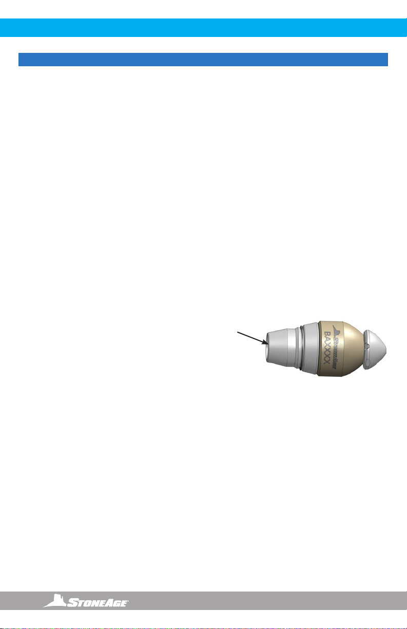
4. The 2” Badger has a large O-Ring (WV 008)
around the inlet. This O-Ring helps prevent
the tool from getting caught on the rear
edge when pulling the tool back out of the
line. An optional Fairing Assembly (BA 530)
will also help prevent snagging during tool
removal.
5. It is recommended that the hose be marked
a few feet from the end with a piece of tape
so the operator knows when to stop on the
way back out.
6. Position the tool in the line opening.
7. Close the dump and slowly bring the pump
up to pressure the rst time to make sure
no nozzles are plugged and the jet thrust is
correct. The Badger should begin to slowly
rotate.
8. Once operating pressure is reached, feed
the tool into the line to begin the cleaning
job.
9. Allow the jets time to do their work by
feeding the hose out at a controlled rate.
10. 2” BADGER ONLY- After the Badger is
removed from the hose, blow out water with
compressed air and spray a light oil such as
WD-40 into the tool.
TROUBLESHOOTING
HEAD WILL NOT ROTATE:
• First, make sure the head (BA 546-LKD) is still
tightened into the shaft (BA 501-LK). A safety
feature built into the shaft stops the tool from
rotating if the head comes loose.
• If the head isn’t loose, try spraying a light oil
such as WD-40 into the tool and rotate head
by hand until it turns freely again.
• Make sure that the jets in the head are not
plugged.
• If the tool still does not rotate after trying the
steps above, it may need to be disassembled
and cleaned on the inside. Follow the
instructions in the “2” Badger Tool Service
Information” section of this manual.
BA 530
Fairing
NOTICE
The most important item in maintaining the Badger tool is ushing high pressure hoses before use. This
keeps debris from entering the tool and preventing a loss in rotation.
866-795-1586 • WWW.STONEAGETOOLS.COM 9
2” BADGER HEAD REPLACEMENT INFORMATION
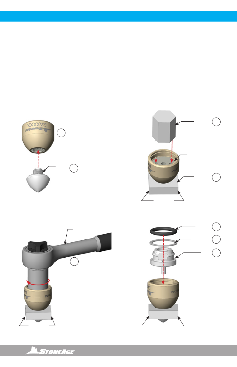
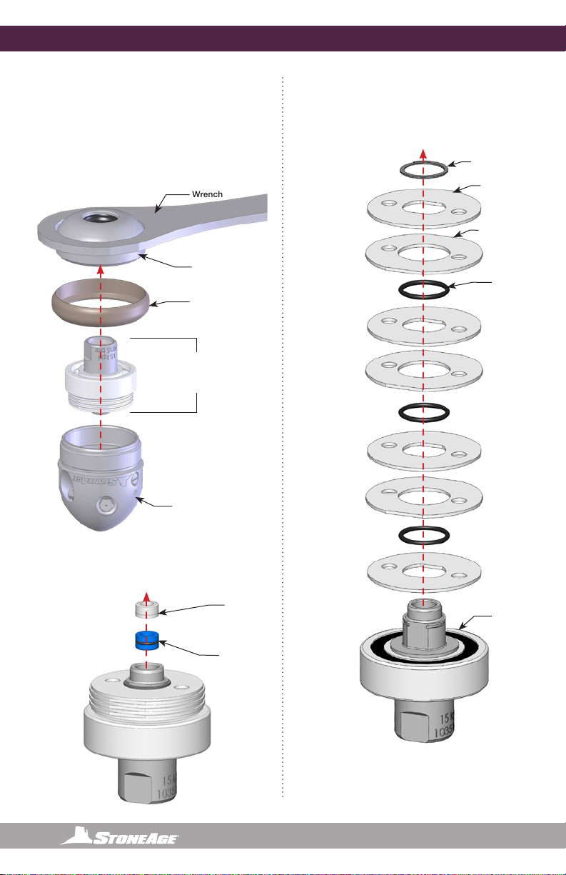
TO REPLACE THE HEAD:
DISASSEMBLY:
1. Slide the BA 182 Head Removal Tool
between the Head and the Shaft to release
the Head Locking Pin. There is only one
direction that will release the Pin. See the
gure below.
2. Leave the Badger in the BA 182 Removal
Tool and clamp the removal tool into a vise.
3. Using a small pick, remove the O-Ring.
4. Using a small at head screw driver, pry the
Retaining Ring off the Inlet Nut, and pull the
Inlet nut out the Shaft.
5. Insert the two pins on the WV 181 Spanner
Wrench into the two bores in the Shaft.
6. Rotate the Spanner Wrench
Counterclockwise with an adjustable end
wrench to remove the Head from the Shaft.
BA 612-LK TOOL KIT INCLUDES:
• BA 182 Head Removal Tool
• BA 185 Red Loctite® 262
• WV 010 Retaining Rings (2)
• WV 181 Spanner Wrench
Loctite®is a registered trademark
of Henkel AG & Co. KGaA.
RECOMMENDED GENERAL TOOLS:
(Not included in the BA-612-LK Kit)
• Bench Vise (recommended)
• Adjustable End Wrench
• 7/8” socket wrench
• Clean lint free rags or blue shop towels
Product training and proper tools are required to service this tool. If you are uncomfortable performing
the service, bring the nozzle to your authorized dealer. Please go to the link below for more information
and service videos for the 2 inch Badger.
https://www.stoneagetools.com/2inch-badger
BA 182
Head
Removal
Tool Head
Locking
Pin
Head
Shaft
1
WV 181
Spanner
Wrench
Shaft
5
Adjustable
End Wrench
Head
6
BA 182
Head
Removal
Tool
O-Ring
Retaining
Ring
Inlet
Nut
Clamp
in Vise
3
4
2
866-795-1586 • WWW.STONEAGETOOLS.COM
10
2” BADGER TOOL SERVICE INFORMATION
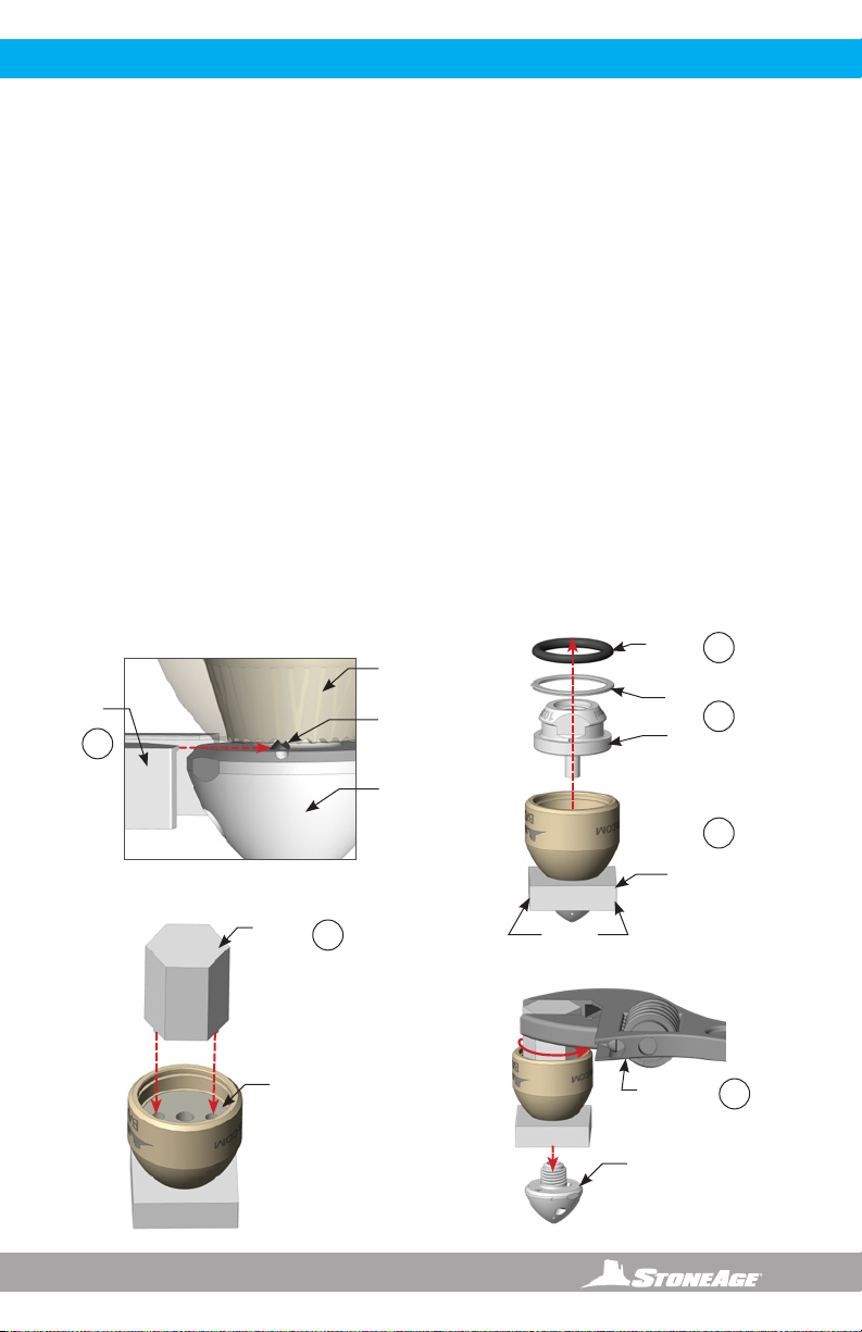
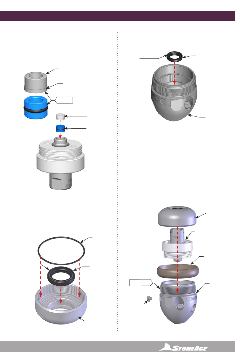
ASSEMBLY:
1. Apply 2-4 drops of BA 185 Red Loctite®262
around the circumference of the threads on
the Replacement Head prior to screwing it
into the Shaft.
2. Care must be taken NOT to allow Red
Loctite®into the internal shaft bore below
the female threads or onto the tapered
external surface of the shaft.
3. Slip the Removal Tool between the Head and
the Body and clamp it into a vise.
4. Insert the WV 181 Spanner Wrench into the
Shaft.
5. Using a 7/8” socket wrench, torque to 100
in-lbs
6. Install the Inlet Nut into the Shaft.
7. Always replace the Retaining Ring with a
new one during each reassembly.
8. Finally, install the O-Ring.
BA 182
Head
Removal Tool
4
3
WV 181
Spanner
Wrench
Shaft
Clamp
in Vise
O-Ring
Retaining
Ring
Inlet
Nut
8
7
6
Clamp
in Vise
Red
Loctite®
2
1
5
Clamp
in Vise
7/8” Torque
Wrench

866-795-1586 • WWW.STONEAGETOOLS.COM 11
2” BADGER ASSEMBLY AND PARTS
BA 546-LKD-A
or
BA 546-LKD-B
or
BA546-LKD-C
Head
NEVER REMOVE
SET SCREW
FROM HEAD
BA 501-LK
Shaft
BA 503
Body
WV 008
O-Ring
WV 010
Retaining Ring
BA 002-P4 (15k)
or
BA 002-BSPP4 (15K)
or
BA 502-MP6R (22K)
or
BA 502-MP9L (22K)
or
BA 502-MP9R (22K)
Inlet Nut
GP 200-BSPP4
Copper Seal Ring .250
REQUIRED FOR BSPP
INLETS ONLY
*Optional
BA 530 Fairing
Accessories
866-795-1586 • WWW.STONEAGETOOLS.COM
12
4” BADGER MODEL DESCRIPTION
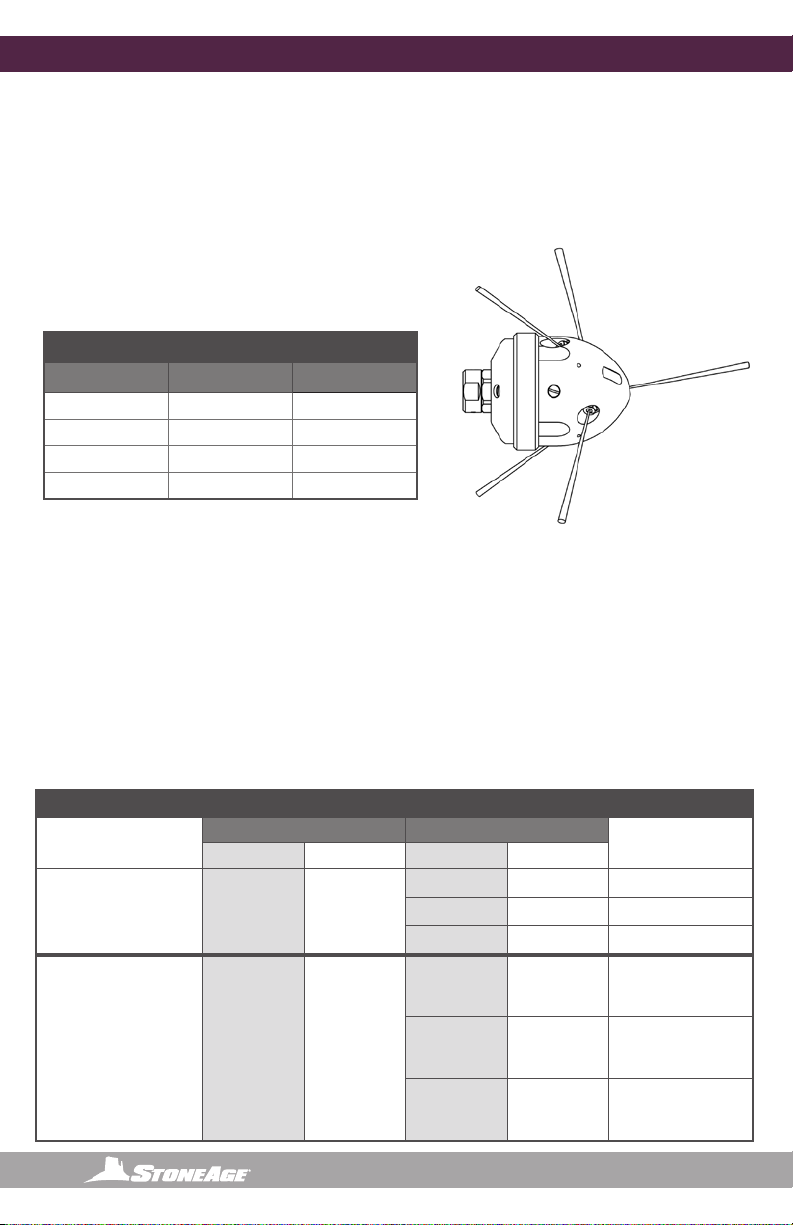
The Badger™ Rotary Waterblast Nozzle was designed for waterblast cleaning of lines with as small as 4
inch with elbows. The tool has an outside diameter of 2.8”. A thin uid is used for rotation speeds of 75
to 250 rpm. The uid in the swivel can be changed to provide either fast or slow rotation. The Badger™
heads have ve 1/8 NPT ports; See diagram and chart below.
4” BADGER TOOL MODEL AND HEAD INFORMATION
4” BADGER
5 Ports:
1 @ 10º
2 @ 100º
2 @ 135º
10˚
135˚
135˚
100˚
100˚
NOZZLES AND PLUGS
The 4” Badger can be jetted in different congurations
depending on the application. The table below shows
commonly used nozzle/plug congurations for the 4”
Badger tool.
4” BADGER NOZZLE AND PLUG CHART
10º PORT 100º PORTS 135º PORTS
1 x Nozzle 2 x Nozzle 2 x Nozzle
1 x Plug 2 x Nozzle 2 x Nozzle
1 x Nozzle 2 x Plug 2 x Nozzle
1 x Plug 2 x Plug 2 x Nozzle
Nozzles are Part Number: AP2-XXX
Plugs are Part Number: GP 025-P2SS
HEAD OFFSET OPTIONS
Engraved on each head is R12, R18 or R22; this number is the offset of the head that makes it rotate.
The approximate ow range for each head offset is given in the table; pump operating pressure, hose
size and hose length, and actual ow rate will precisely determine the correct head offset and nozzle
sizes to match operating conditions. Refer to the StoneAge Jetting App Calculator to aid in proper
head selection. If the resulting pressure and ow is below the correct range for a head offset the tool
may not rotate; if it is more than the allowable the tool may rotate too fast and quickly wear out the
seals and bearings
4” BADGER HEAD OFFSET CHART
MODEL / INLET
CONNECTION
PRESSURE RANGE FLOW RANGE
HEAD
psi bar gpm lpm
BAE-P6
3/8 NPT FEMALE 5000-15K 345-1035
12-16 45-60 BAE 040-R22
16-23 60-87 BAE 040-R18
23-35 87-132 BAE 040-R12
BAE-BSPP6
3/8 BSPP FEMALE
BAE-MP9R
9/16 FEMALE
BAE-MP9L
9/16 FEMALE
BAE-M24 X 1.5
24mm MALE
5000-22K 345-1500
12-16 45-60 BAE 040-R22
16-22 60-83 BAE 040-R18
22-34 83-130 BAE 040-R12
Once you have conrmed the required jetting conguration, use the StoneAge Jetting App to determine
nozzle sizes: Jetting.stoneagetools.com
866-795-1586 • WWW.STONEAGETOOLS.COM 13
4” BADGER BACKOUT PREVENTION
IMPROPER USE:
Badger will turn around in
large diameter line
VERY DANGEROUS!
PROPER USE:
Badger with rigid “stinger”
to prevent turnaround, still
able to pass through elbows.
Rigid
Stinger
1-1/2 times
line ID
WARNING
Because of the short length of the Badger, the tool can turn around in large lines and come back at the
operator at a high rate of speed. If cleaning larger lines, a rigid “stinger” should be used between the
hose and the tool. It is recommended that the rigid length of the tool including hose end is 1-1/2 times
the inside diameter of the line being cleaned (see below).
Make sure there is an operator controlled dump in the system, operated by the person closest to the
cleaning job.
Follow all operating instructions in this manual.
DANGER
If the 4” BADGER is being used in larger diameter lines, a rigid stinger should be installed between the
tool inlet and the hose end; otherwise the tool can turn around and come back toward the operator,
causing serious injury or death.
Operations with this equipment can be potentially hazardous. Caution must be exercised prior to and
during machine and water jet tool use. Please read and follow all of these instructions, in addition to the
guidelines in the WJTA Recommended Practices handbook, available online at www.wjta.org.
Deviating from safety instructions and recommended practices can lead to severe injury and/or death.
866-795-1586 • WWW.STONEAGETOOLS.COM
14
4” BADGER OPERATION AND TROUBLESHOOTING
OPERATION:
NOTICE
The two most important items in maintaining the
Badger tools;
- Keep debris from entering the tool and pre-
venting it from rotating by ushing high pressure
hoses before use.
- Keep the 4” and 6” models full of viscous uid
to maintain control and rotation speed. When the
viscous uid is lost or contaminated, the rotation
speed of the tool will increase, which reduce the
life of the high pressure seal and bearing.
1. Make sure the operator has a controlled
dump in the system and it is operated by
the person closest to the job. Test the dump
prior to beginning the job.
2. Flush out the high pressure hoses before
connecting the Badger™ to eliminate debris.
3. Attach tool to the end of the hose.
4. It is recommended that the hose be marked a
few feet from the end with a piece of tape so
the operator knows when to stop on the way
back out.
5. Position the tool in the pipe opening.
6. Close the dump and slowly bring the pump
up to pressure the rst time to make sure
no nozzles are plugged and the jet thrust is
correct. The Badger should begin to slowly
rotate.
7. Once operating pressure is reached, feed the
tool into the pipe to begin the cleaning job.
8. Allow the jets time to do their work by
feeding the hose out at a controlled rate.
9. When the work is complete and the tool is
disconnected from the hose, blow out all
water to prolong the life of the tool.
10. A small amount of 3-IN-ONE or equivalent
lubricant can be blown into the tool as well.
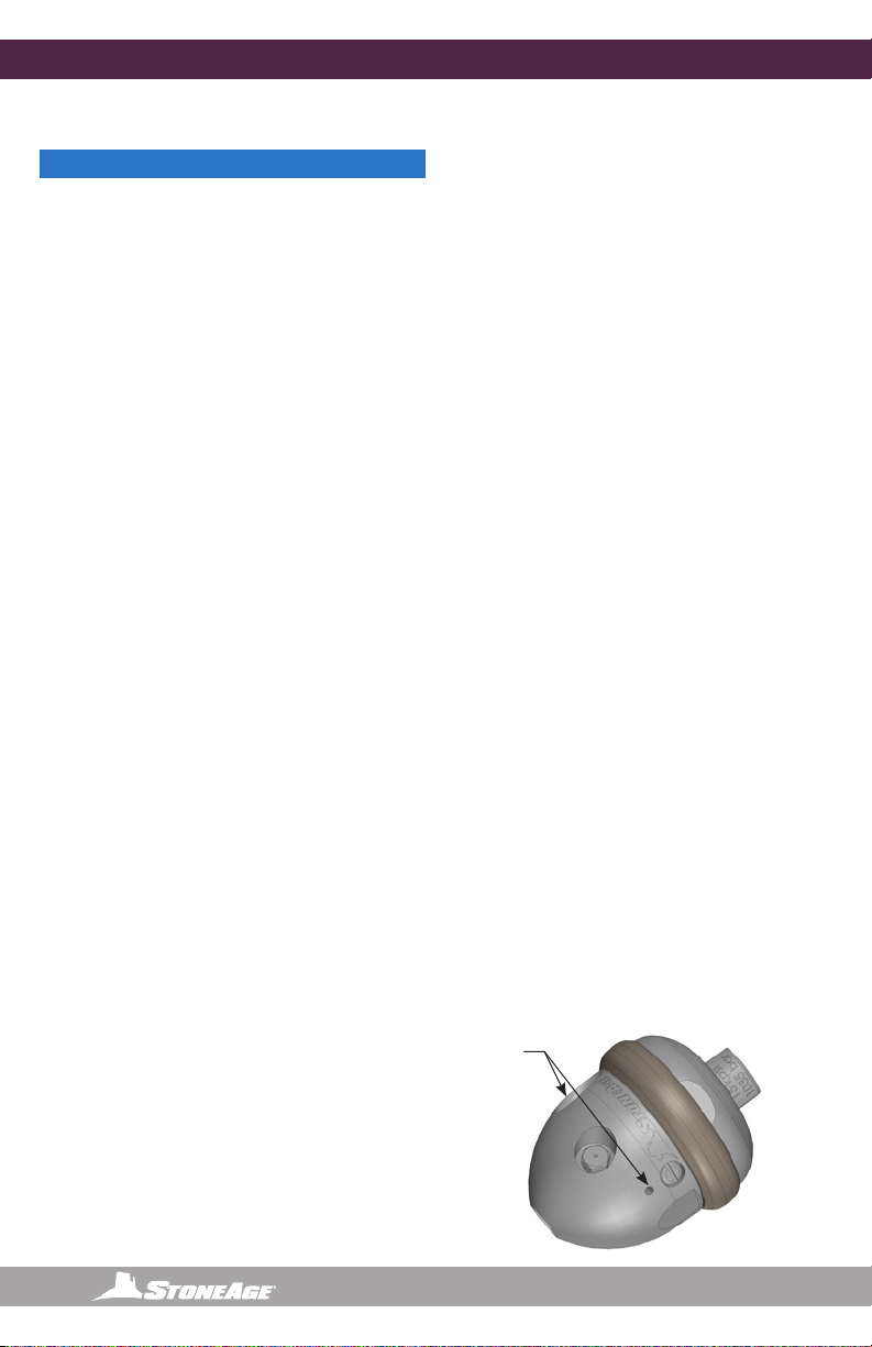
TROUBLE SHOOTING:
HIGH-PRESSURE WATER SEAL LEAK:
• The high pressure seal may leak initially at
lower pressures, but should pop closed as
pressure is increased. A continuous leak
at operating pressure from the weep holes
indicates the need to replace the HP Seal and
Seat. HP Seals wearing out too quickly can
be an indication that the shaft bore is worn,
the HP Seat is installed upside-down, or the
tool is over spinning. Over spinning is caused
by low or contaminated viscous uid, water
in the uid chamber (replace shaft seals), or
too much jet torque. Relling the viscous uid
every 80-100 hours of operation is important
for proper speed control. Only use StoneAge
recommended viscous uid.
TOOL SPINS TOO FAST:
• A signicant increase in rotation speed means
that the speed control mechanism in the tool
has lost functionality. This can be a result
of viscous uid loss or uid contamination.
Operation of the tool in this state can
cause damage to other components and
accelerated wear of the high pressure seal. If
this occurs, the rst step is to ush the tool
with new viscous uid as shown below.
TOOL WILL NOT ROTATE:
• Check the nozzles for plugging or wear
(nozzles have to be removed to check for
obstructions), Check that the nozzle sizes
are correct for the desired ow and that the
desired ow matches the head ow range.
Check that the nozzle sizes are installed in
a balanced conguration. If the tool feels
rough when manually rotating the head, this
indicates internal damage. Replace bearings,
shaft seals, viscous uid, and check the Inner
and Outer Discs for atness. These discs
can be deformed if tool is reassembled
when discs are not properly aligned with the
internal ats inside the head.
WEEP
HOLES

866-795-1586 • WWW.STONEAGETOOLS.COM 15
4” BADGER TOOL SERVICE INFORMATION
TOOL SERVICE
Product training and proper tools are required to service this tool. If you are uncomfortable performing the
service, bring the nozzle to your authorized dealer. Please go to the link below for more information and
service videos for the 4 inch Badger.
https://www.stoneagetools.com/4inch-badger
The use of a bench vice and an arbor press is highly helpful. Take care throughout the entire procedure
to keep the internals clean and free from grit, lint, and contamination. Failure to do so could result in
premature tool failure after service.
LIST OF TOOLS:
• Bench Vise (recommended)
• Arbor Press (recommended)
• 18” adjustable wrench (such as Crescent®C718
Automatic Adjustable Pipe Wrench)
• 13/16” open end wrench or small adjustable
Crescent®Wrench
• Medium size at-head screw driver
• Pick
• BAE 612 Tool Kit for 4” Badger Includes;
BAE 181 Wrench
BA 105 Seal Press Tool
LIST OF MATERIALS:
• Clean lint free rags or shop towels
• Anti-Seize - Swagelok®Blue Goop®
StoneAge PN (GP 043 Blue Goop)
• Grease - Chevron Multifak®EP1
StoneAge PN (GP 049)
• Isopropyl Alcohol or Denatured Alcohol
Blue Goop®is a registered trademark of Swagelok®
Company
Multifak®is a registered trademark of Chevron®
Corporation.
VISCOUS FLUID FLUSH INSTRUCTIONS
1. Remove both Port Plugs in the Head
(BAE 040-RXX) (see below).
2. Fill the Syringe with viscous uid by
removing the end near the handle,
pulling out the plunger, and pouring the
Viscous Fluid (BJ 048-F) in to ll the
Syringe Body. With plunger re-installed,
purge air out of Syringe hose.
3. Thread the syringe end into a port in the
Head. Hold the tool sideways, so the
bleed port is on top and the injection
port is on the bottom. Squeeze fresh
Viscous Fluid in until clean Viscous
Fluid comes out the bleed port. Keep
ushing new uid until air bubbles stop
coming out of the bleed port.
4. Install a Port Plug into the bleed side
rst. Remove the Syringe and install
the Port Plug back into the Injection
side port.
BJ 026
Port Plug
(Bleed)
BJ 026
Port Plug
(Injection)
BAE 040-RXX
Head
BC 410
Syringe
REMOVE
TO FILL
Viscous Fluid Flush
866-795-1586 • WWW.STONEAGETOOLS.COM
16
4” BADGER DISASSEMBLY
Figure 2: For Step 4
BAE 017
Retaining Ring
BAE 015
Inner Disc (4)
BAE 016
Outer Disc (3)
BAE 010
O-Ring (3)
Figure 3: For Step 5-6
4. Use a small pick to remove the Carbide Seat
and H.P. Seal from the bore of the Shaft.
BAE 181
Wrench
Shaft /Bearing
Assembly
RJ 011-C
Carbide
Seat
RJ 012-TO
H.P. Seal
5. Use a small screw driver or pick to remove
the Retaining Ring from the shaft.
6. Pull the Discs and O-Rings off of the Shaft.
DISASSEMBLY
1. Use an adjustable end or BAE 181 wrench
on the ats of the Nut and remove it from the
Head.
2. Slip off the Wear Ring.
3. Lift the Shaft Assembly out of the head.
Figure 1: For Steps 1-3
BAE 030
Wear Ring
BAE 002
Nut
BAE 040-Rxx
Head
Shaft, Bearing,
Carbide, HP Seal,
and
Disc Stack

866-795-1586 • WWW.STONEAGETOOLS.COM 17
BA 006
Shaft Seal
BAE 008
O-Ring
BRLM 109
Bearing
BAE 001-Px
Shaft
4” BADGER DISASSEMBLY
Figure 4: For Step 7
Figure 5: For Step 8
7. Use an arbor press to press the Bearing off
of the Shaft. Be sure the bearing is set at on
the press before applying pressure. Pressing
the shaft out of the bearing at an angle could
cause damage to the bearing.
9. Remove both Port Plugs from the Head.
10. Use a at head screwdriver to remove the
Shaft Seal and inspect for damage.
Figure 6: For Steps 9-10
8. Use a small pick to remove the O-Ring and
the Shaft Seal and inspect both for damage.
BA 007
Shaft Seal
BAE 002
Nut
BJ 026
Port Plug
BAE 040-Rxx
Head
INSPECT
INSPECT
NOTICE
Before reassembly of the tool
Wash all parts in solvent and blow dry
and
Inspect wear items, (High Pressure Seal
Assembly, O-Rings, and Port Screw.)
See the “Maintenance Kits” section of this
manual for a complete list of Service, Overhaul,
and, Tool kits.

866-795-1586 • WWW.STONEAGETOOLS.COM
18
4” BADGER ASSEMBLY
ASSEMBLY
1. Grease the open side of the Bearing.
2. Note the orientation of the Bearing before
pressing it onto the Shaft. The greased side
should be down. Use an arbor press to
press the Bearing onto the Shaft. Be sure
the bearing is set at on the press before
applying pressure. Pressing the shaft into the
bearing at an angle could cause damage to
the bearing.
3. Align the internal ats of an Inner Disc with
the ats of the Shaft and place over the Shaft.
4. Place an O-Ring on top of this Disc.
5. Place an Outer Disc on after the O-Ring. The
external ats of the Outer Discs should be
aligned with the ats inside the head.
6. Repeat these steps until there are three Outer
Discs and four Inner Discs on the Shaft.
7. Push down on top disc and install the
Retaining Ring in the groove around the
Shaft.
BAE 001-xx
Shaft
Figure 7: For Steps 1-2
BRLM 109
Bearing
BAE 017
Retaining Ring
BAE 015
Inner Disc (4)
BAE 016
Outer Disc (3)
BAE 010
O-Ring (3)
The Outer
Disc ats
will align
with the
ats inside
the head
Align Inner
Disc ats to
Shaft ats
GREASE
Figure 8: For Steps 3-7
GREASE
ANTI-SEIZE
= Chevron Multifak®EP1 Tan
= Swagelock®Blue Goop or Equal
866-795-1586 • WWW.STONEAGETOOLS.COM 19
4” BADGER ASSEMBLY
8. Apply grease to the H.P. Seal and install into
the bore of the Shaft.
9. Apply grease to the Flat Face of the Seat and
place into the bore of the Shaft, on top of H.P.
Seal, as shown.
Figure 10: For Steps 10-11
BA 007
Shaft Seal
BA 006
Shaft Seal
BAE 002
Nut
Figure 9: For Steps 8-9
RJ 011-C
Seat
RJ 012-TO
H.P. Seal
Chamfered
Face
Flat
Face
Figure 12: For Steps 13-15
BAE 008
O-Ring
Figure 11: For Step 12
10. Install the Shaft Seal into the center of the Nut
with the lip spring side up.
11. Install the O-Ring in the groove in the bottom
of the Nut.
BAE 002
Nut
BAE 030
Wear Ring
Shaft/Bearing
Assembly
BJ 026
Port Plug
12. Install the Shaft Seal into the Head with the
lip spring side up.
13. Align the ats on the Outer Discs with the
ats inside the Head; slide shaft assembly
into the Head.
14. Apply anti-seize to threads on Head; install
the Wear Ring onto the Head; thread the Nut
onto the Head and tighten to 50 ft-lb.
15. Follow the “Lubricant Replacement
Instructions” Section before installing the
Port Plugs back into the head.
BAE 040-Rxx
Head
Lip Spring
Side
GREASE
ANTI-SEIZE
Lip Spring
Side Up
BAE 040-Rxx
Head
866-795-1586 • WWW.STONEAGETOOLS.COM
20
4” BADGER PART NUMBERS AND SERVICE KITS
4” BADGER KITS AND KIT CONTENTS
BAE 600-F
SERVICE KIT (FAST)
BAE 600-S
SERVICE KIT (SLOW)
BAE 602
H.P. SEAL KIT
1 BC 410 Syringe Assembly
1 BJ 048-F Visc Fluid, Fast, 6oz
1 BJ 062-S Anti-seize, 2g
1 RJ 011-C Carbide Seat
1 RJ 012-TO H.P. Seal and O-Ring
1 PL 663 BADGER Family Manual
1 BC 410 Syringe Assembly
1 BJ 048-S Visc Fluid, Slow, 6oz
1 BJ 062-S Anti-seize, 2g
1 RJ 011-C Carbide Seat
1 RJ 012-TO H.P. Seal and O-Ring
1 PL 663 BADGER Family Manual
1 RJ 011-C Carbide Seat
1 RJ 012-TO H.P. Seal
and O-Ring
BAE 610-F
OVERHAUL KIT (FAST)
BAE 610-S
OVERHAUL KIT (SLOW)
BAE 604
DISC KIT
1 BA 006 Seal
1 BA 007 Seal
1 BAE 008 O-Ring
3 BAE 010 O-Ring
1 BAE 017 External Retaining Ring
1 BJ 026 Port Plug
1 BJ 048-F Visc Fluid, Fast, 6oz
1 BJ 062-S Antiseize, 2g
1 BRLM 109 Bearing, Single Sided
1 PL 663 BADGER Family Manual
1 RJ 011-C Carbide Seat
1 RJ 012-TO H.P. Seal and O-Ring
1 BA 006 Seal
1 BA 007 Seal
1 BAE 008 O-Ring
3 BAE 010 O-Ring
1 BAE 017 External Retaining Ring
1 BJ 026 Port Plug
1 BJ 048-S Visc Fluid, Slow, 6oz
1 BJ 062-S Antiseize, 2g
1 BRLM 109 Bearing, Single Sided
1 PL 663 BADGER Family Manual
1 RJ 011-C Carbide Seat
1 RJ 012-TO H.P. Seal and O-Ring
3 BAE 010 O-Ring
4 BAE 015 Inner Disc
3 BAE 016 Outer Disc
1 BAE 017 External Retaining Ring
1 PL 663 BADGER Family Manual
BAE 612
TOOL KIT
1 BAE 181 Wrench
1 BA 105 Seal Press Tool
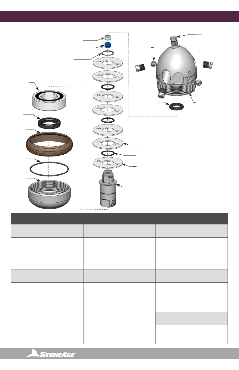
BRLM 109
Bearing
BA 007
Shaft Seal
BAE 030
Wear Ring
BAE 002
Nut
BAE 008
O-Ring
BAE 001-xx
Shaft
BAE 017
Retaining Ring
BAE 015
Inner Disc (4)
BAE 016
Outer Disc (3)
BAE 010
O-Ring (3)
RJ 011-C
Carbide Seat
RJ 012-TO
H.P. Seal
AP2-XXX
Nozzles (5)
BA 006
Shaft Seal
BJ 026
Port Plug (2)
BAE 040-Rxx
Head
This manual suits for next models
13
Table of contents
Other StoneAge Pipe Cleaner manuals


