Spartherm Mellino User manual

Operating Instructions
Pellet Stove Mellino

GB 2
PREFACE
You have decided in favour of a Spartherm pellet stove - thank you for your
confidence in our company.
In a world of excess and mass production we hold to the motto of our owner
Gerhard Manfred Rokossa:
„High technical quality combined with contemporary design and service to the
satisfaction of our customers so they will recommend us to others“. Together
with our specialist trade partners, we offer a range of first-class products,
which not only evoke passion, but also engender feelings of comfort and
security.
To ensure that this occurs, we encourage you to read the operating and instal-
lation instructions carefully so that you can become familiar with your fireplace
quickly and thoroughly.
As well as information about operation, this manual also contains important
instructions concerning installation and maintenance. In addition to opera-
tional reliability, compliance with these instructions also contributes to the
value retention of your pellet stove.
For further enquiries, please contact your specialist dealer.
May your fire keep burning beautifully.
Your Spartherm Team
G.M. Rokossa

GB 3
GB
CONTENT
1. Information 4
1.1 General information 4
1.2 Rating plate 4
1.3 Safety instructions 4
1.4 Safety functions 6
1.5 Fuel – wood pellets 7
2. Operation and startup 8
2.1 Startup 8
2.2 Filling the fuel tank 8
2.3 The display 8
2.4 The remote control unit 9
2.5 Switching the pellet stove on and off 10
2.6 Operating modes of the pellet stove 10
2.7 Adjusting the heating capacity 11
2.8 Adjusting the hot-air blower 12
2.9 Adjusting the target room temperature 12
2.10 Setting the pellet type 12
2.11 Setting the time / date and time 13
2.12 Timer operation – general information 13
2.13 Activating / switching off the timer 14
2.14 Selecting a switch program 14
2.15 Querying / deleting a switch program 14
2.16 Changing switch program data 15
2.17 Service menu 15
3. Cleaning and maintenance 17
3.1 Maintenance intervals 17
3.2 Cleaning the view pane 17
3.3 Cleaning the burner plate 18
3.4 Cleaning the pellet chute 19
3.5 Cleaning the ignition device 19
3.6 Cleaning the combustion chamber 20
3.7 Emptying the ash drawer 20
3.8. Cleaning the hot-gas flues 21
3.9 Cleaning the flue gas manifold 21
3.10 Cleaning the ash collector 22
3.11 Yearly inspection 22
4. Troubleshooting 23
5. General warranty conditions 23
5.1 Range of application 23
5.2 General information 23
5.3 Warranty period 24
5.4 Warranty requirements 24
5.5 Exclusions from the warranty 24
5.6 Elimination of defects / repair 24
5.7 Extension to the warranty period 25
5.8 Spare parts 25
5.9 Liability 25
5.10 Closing remarks 25
6. Technical data 25
7. Declaration of Conformity 26
8. Commissioning and Service Protocol 26

GB 4
1. INFORMATION
1.1 GENERAL INFORMATION
These operating instructions describe the operation and the most important
maintenance tasks for the Mellino pellet stove. These instructions have been
prepared primarily for the user of the pellet stove.
Failure to comply with the operating instructions can cause mal-
functions and severe appliance damage extending to total loss. If
the operating instructions are not complied with the warranty is
rendered null and void.
Instructions concerning installation, commissioning and extensive service
information for the Mellino are provided in the „Installation and Service
Instructions – Mellino“.
Only use top-quality pellets as fuel; pellets that satisfy the requirements
specified under „1.5 Fuel – wood pellets“.
It is not permitted to burn:
• Wet pellets (residual moisture > 20%) or pellets that become wet
• Logs, chipboard, wood chips, straw, etc.
• Painted or plastic-coated wood of any type
• Rubbish, household waste, old clothes
• Paper, paper briquettes, cardboard
• Plastic or foam of any kind
• Other solid or liquid fuels
Burning these materials in your pellet stove is prohibited. If the Mel-
lino is operated with non-approved fuels the warranty is rendered
will void!
Various moving parts are installed in a pellet stove; without these moving
parts operation is not possible. These parts can cause noises. The type of
noise can change over time. Consequently, a certain level of noise is una-
voidable when the appliance is plugged in and does not constitute reason
for complaint.
1.2 RATING PLATE
The rating plate is under the pellet tank lid.
The serial number is at the upper left and is V4-5-xxxx.
1.3 SAFETY INSTRUCTIONS
Please comply with the following instructions so that you can enjoy an
undisturbed fire experience with your Mellino:
• Carefully read the operating and installation instructions all the way
through and comply with the notices and recommendations contained
therein.
• The appliance must be set up on a fireproof substrate in such a manner
that the appliance is stable and safe. It should not be slanted on any side
• During operation of the pellet stove parts of the cladding, the view pane
and the flue pipe connection become very hot. Touching these parts
without appropriate protective equipment can result in injury.
• Keep children away from the fireplace during operation or make them
aware of the possible hazards. The pellet stove is not a toy - danger of
burn injuries!
• ATTENTION: The provided heat-resistant glove serves only as thermal
protection when activating the cold hand and the lift-out tool. The glove
is not fire-proof.
• This pellet stove is not intended to be used by people with restricted
physical, sensory or mental capacities, unless they are supervised by a
person responsible for their safety or have received instructions on how
to use the appliance from this person

GB 5
GB
• Do not place any objects on the pellet stove or in the area of its direct
radiant heat - fire hazard!
• Do not operate the fireplace over an extended period of time unattended
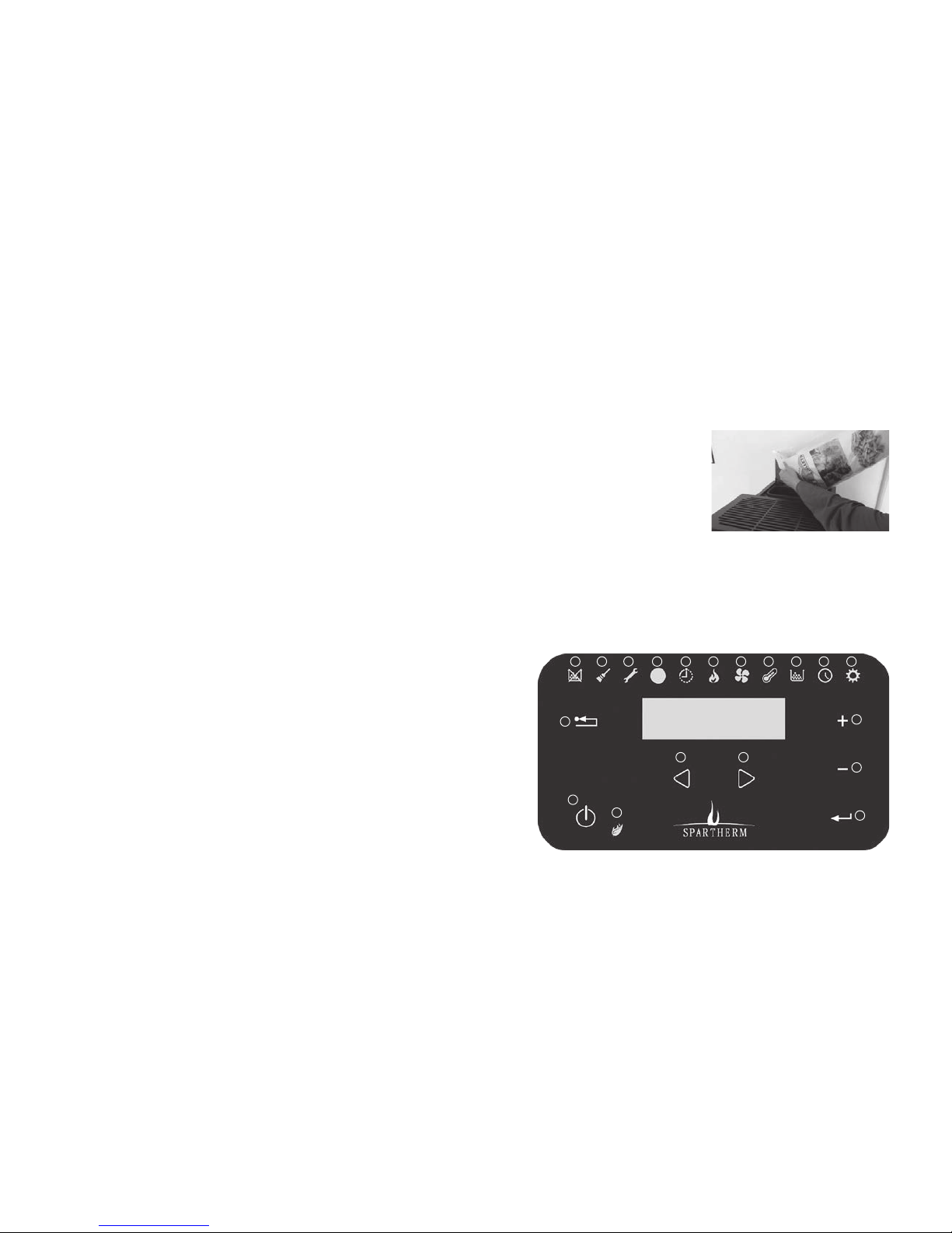
• When filling the fuel storage tank, ensure that pellets do not fall onto
the convection fins or on hot parts of the cladding - danger of smoke
development!
• Only open the combustion chamber door to clean the combustion cham-
ber and burner plate, and only open the combustion chamber door when
the appliance is switched off and in cold status. Opening the combustion
chamber door during operation triggers an error message and the pellet
stove will be switched off automatically! Close the door again properly
after cleaning.
• If the power cable of this appliance is damaged, it must be replaced by
the customer service organization or a person with similar qualifications
(e.g. qualified electrician) to avoid a hazard.
• The ambient temperature is above about 15°C. The weather conditions
and supply pressure are unfavourable (e.g. fog). These weather condi-
tions occur most frequently in spring and fall. The burnup may therefore
be slightly uneven.
• Your fireplace draws the combustion air from the installation area (open
flue operation). Ensure that there is a sufficient supply of fresh air to
the room in which the stove is installed (for more details, refer to ‚Gen-
erally recognised rules of technology‘ or speak to your local chimney
sweep. The fresh air supply must be checked by the installer and the
operator. When operating several fireplaces in a single room or a linked
space, ensure that sufficient air is available for complete combustion!
It is possible that there is not a sufficient supply of fresh air if the
windows and doors are sealed (e.g., in combination with energy saving
measures). As a result, the ventilation of the tiled stove can be affected.
This can adversely affect your well-being and, potentially, your safety.
If necessary, an air flap must be installed near the pellet stove for the
additional supply of fresh air, or a combustion air line must be routed
outwards or in a well-ventilated room (except for the heating room).
In particular, ensure that the necessary combustion air pipes are open
during the operation of the fireplace insert. Simultaneous operation
with a ventilation system (e.g. extractor hood, bathroom fan, etc.) in the
same room or connected space can adversely affect the function of the
fireplace (to the point of smoke or flue gas accumulating in the living
room, despite the firebox door being closed). It is therefore prohibited to
operate appliances of this kind simultaneously with a fireplace without
first taking appropriate precautionary measures. If any questions arise,
please contact your chimney sweep.
• Your pellet stove is connected to the chimney with Ø 100 mm connecting
pieces made of steel plate which is at least 2 mm thick. These must
comply with the ‚Generally recognized rules of technology‘ and must
therefore be connected properly to the chimney. The connecting piece
must be routed to follow the shortest route between fireplace insert and
chimney. The flue gas path must never point downwards. Instead, it must
wherever possible always be directed upwards towards the chimney.
To achieve this, ensure that the flow of flue gas is redirected as few
times as possible. Ensure that the exhaust pipe is stable/robust; where
appropriate, the exhaust pipe may need to be secured with brackets.
If the flue leads through a combustible wall or is located close to any
combustible components, the flue is to be insulated according to the
respective regulations. In all cases, the connecting line must be installed
in a way that enables it at any time to be cleaned easily and reliably.
This must be ensured through a sufficient number of cleaning openings.
The minimum distance from the connecting piece to any combustible
components can increase the distance from the fireplace to combustible
components, in accordance with manufacturer specifications. The speci-
fied minimum distances to combustible components as stated in these
instructions refer to the fireplace and must be adjusted if necessary.
• The combustion of solid fuels will cause sparks to travel from the
fireplace into the chimney. This may ignite the soot in the chimney.
(this rarely happens if the chimney is cleaned regularly by the chimney
sweep). You can detect a chimney fire by:

GB 6
• flames emerging from the mouth of the chimney;
• a lot of flying sparks;
• smoke and odour problems
• sides of chimney becoming progressively hotter.
It is important to act properly in such cases. You can alert the fire
brigade by dialling 999 (or 112 in Germany). The chimney sweep
should also be informed. Combustible objects should be located away
from the chimney. Attention: Do not attempt to extinguish the fire with
water before the fire brigade arrives on the scene. Temperatures in
a chimney fire can reach up to 1300°C. Extinguishing water would
immediately create steam. A 10-litre bucket of water yields 17 cubic
meters of steam. The enormous pressure created as a result could
cause the chimney to disintegrate. After a fire, the entire combustion
system must be checked by a specialist for signs of damage and, if
necessary, be repaired.
1.4 SAFETY FUNCTIONS
The control system of the Mellino pellet stove offers safety functions that
trip automatically if there is a malfunction:
If the pellet stove switches off due to an error, the cause of the error will
be displayed on the operating panel as an error code (see chapter 4.
Troubleshooting).
Lack of fuel
If the pellet tank should be run empty the fire will be extinguished because
the minimum temperature has been underranged. An error message will be
generated that indicates the lack of pellets. After acknowledging the error,
filling up the pellet tank and filling up the screw feeder, the pellet stove can
be restarted.
Flue gas fan
The flue gas fan is monitored by the control system If the flue gas fan
fails, the pellet stove can no longer be switched on, an error message is
displayed. If there is a flue gas fan error the customer service organisation
must be notified. In this case the appliance should no longer be operated.
Electrical overload protection
The pellet stove is safeguarded against overcurrent and internal short-
circuit with an internal main fuse.
Power outage during operation
After a brief power outage (to approximately 30 s), combustion will be
resumed with the previously set operating parameters.
In the case of a longer power outage, after the power outage the control
system goes into the ignition procedure and restarts the pellet stove with
the set parameters.
Power outage during the start phase
After a brief power outage the start procedure will be continued.
In the event of a longer power outage, after power is restored the control
system will go into switch off mode and then restart the pellet stove with the
previously set operating parameters.
Low-temperature switch off
If in operation the normal flue gas temperature is underranged for a longer
period of time, or if it is not reached (e.g. due to wet pellets, poor pellet
quality or a lack of maintenance or cleaning) the control system will initiate
switch off of the appliance.
The pellet stove can only be started up again after acknowledging the error
message.
Overtemperature switch off
If an operation, the normal flue gas temperature is exceeded for an extended
period of time (e.g. due to unsuitable fuel, or lack of maintenance or clean-
ing), the control system switches off the appliance.
The pellet stove can only be started up again after acknowledging the error
message

GB 7
GB
Open combustion chamber door
If the combustion chamber door is open during operation, after 20–30 sec-
onds the extinguishing procedure will be triggered so that toxic flue gases
in hazardous quantities cannot get into the installation room.
Overheating
The screw feeder and the pellet storage tank are monitored by an STL
(safety temperature limiter). If the preset safety temperature on the STL
is exceeded, the appliance will be switched off by the control system.
The appliance can only be switched back on after it has cooled and after
acknowledging the error message on the operating panel.
ATTENTION:
If the appliance has been switched off due to insufficient temperature, over-
temperature or overheating, the cause of the error must be identified and
eliminated prior to switching the pellet stove back on.
If the appliance is further operated improperly or if safety devices are ren-
dered inoperable, the operating license and guarantee are rendered null
and void!!
1.5 FUEL – WOOD PELLETS
Wood pellets are a fuel that consists of wood shavings pressed into a rod
shape. The pellets are obtained primarily from sawmill waste wood, and
from wood that has been broken off of trees in forestry operations. For the
Mellino, only use quality pellets that meet the requirements stipulated in
DIN 51731 or EN 14941-2. In addition to these requirements the wood pel-
lets must meet the requirements specified in DINplus (HP5) or the Austrian
standard ÖNorm M 7135 (HP1).
Look for these marks:
Do not use fuels such as corn (maize), straw, wood chips, etc!
Note:
The use of low-quality or unsuitable pellet fuel can impair the function of
your pellet stove and renders the warranty null and void. Burning pellets
with a high proportion of bark (resin content) can result in higher heating
capacity and thus cause the overtemperature thermostat to trip. In addition,
an increased resin content can cause significant view pane contamination.
We recommend the use of pellets that are as light in colour as possible.
If possible always empty complete sacks into the tank. Do not leave the
pellet sacks open, this will cause the pellets to become moist.

GB 8
2. OPERATION AND STARTUP
The pellet appliance must only be started up in completely assembled
status.
Comply with all maintenance and cleaning guidelines (chapter 4.0) to enjoy
an undisturbed heating experience.
2.1 STARTUP
1. Only start up the pellet stove if the daily maintenance or cleaning tasks
specified in chapter 3.1 have been executed. No damage must be pre-
sent on the Mellino before it goes into service, e.g. defective viewing
pane.
2. Ensure that the burner plate is cleaned and is seated precisely in its
intended receptacle. The surface of the plate will then be flush with (at
the same height as) the surrounding receptacle. In this regard strictly
comply with the instructions in chapter 3.3.
3. Check whether the pellet tank is sufficiently filled with fuel and that the
lid of the tank is closed. If this is not the case, chapter 2.2 describes
how to fill the tank, while chapter 2.17 below level [6] describes how to
fill the feeder screw with fuel.
4. Ensure that no error messages are shown on the display.
5. Now the pellet oven can be started up via the On/Off switch or via the
remote control unit.
6. Now, after a few seconds, pellets drop into the burner plate and, a 5 - 10
minutes later, these ignite on the plate.
2.2 FILLING THE FUEL TANK
Only use wood pellets with the qualities specified under 1.5 as fuel.
Lift up the tank lid via the recess and move the lid to the vertical posi-
tion. Now fill the tank, ideally with a
complete bag of pellets In particular
when the oven is burning fuel, it is
advisable to fill the tank from the
side. Close the tank lid after filling
it.
2.3 THE DISPLAY
The first 3 symbols, at top left, are warnings. Adjacent to these 3 symbols
is the receiver for the remote control unit and a display that shows whether
a timer program is activated. With the menu buttons you can move to the
other 6 displays and then set them.
1
2
3 4 5 6 7 8 9 10 11 12 13
14
15
16
18
19
17

GB 9
GB
1On/Off switch
2ESC button (back) Also error code query
3Warning: Flue gas temperature too low or lack of pellets
4Warning: Clean appliance or flue draft is clogged
5Warning: Error please read out the error code and contact customer
service
6Receiver for the infrared remote control unit
7Is illuminated when the timer program is activated
8Current heating capacity (1, 2, 3, 4, Auto or Hi)
9Output level – hot-air blower (1, 2, 3, 4, 5 or Auto)
10 Room temperature and target temperature in °C
11 Selection – pellet type (1, 2 or 3)
12 Time and timer program
13 Service menu
14 Adjustment buttons
15
16 ENTER button
17 Menu buttons
18
19 Status light
2.4 THE REMOTE CONTROL UNIT
The most important settings of the pellet oven can also be made via the
provided infrared remote control unit.
Unobstructed line-of-sight contact to the display of the pellet stove is
required to control the pellet stove via the remote control unit. The receiver
is in the upper area of the display. The commands of the remote control
unit are shown on the display. To change batteries, first pull the catch hook
towards the middle and hold it, then pull out the battery compartment, as
depicted on the remote control unit. Battery type: Button cell CR2032, 3
volt.
On/Off switch
(button 1)
Heating capacity higher
(button 2)
Target room temperature
higher (button 4)
Heating capacity higher
(button 2)
…lower (button 5)

GB 10
2.5 SWITCHING THE PELLET STOVE ON AND OFF
The pellet stove is operated via the display integrated in the side cladding
element or via the provided remote control unit. The display does not have
pushbuttons but rather sensor buttons. It suffices to place your fingertip
in the button recess. Stronger pressure does not result in activation of the
button.
Switching the pellet stove on and off on the display:
• Press the On/Off button – the pellet stove goes into the ignition proce-
dure. The button must be activated for 2 seconds, also for switch off.
Shortly thereafter the display shows ON or OFF depending on whether
the appliance was switched ON or OFF.
• To switch off, the ON/OFF switch is activated again
Switching the pellet stove on/off with the remote control unit:
• Press button 1, the On/Off switch, on the remote control unit to switch
the Mellino on or off. To do this you must have a clear line of sight to the
display of the appliance.
• After switch on, during the ignition phase, the status LED flashes at one
second intervals. When the stove has reached its operating temperature
the LED is continuously illuminated. As soon as the stove is switched off,
the status LED goes out.
2.6 OPERATING MODES OF THE PELLET STOVE
The Mellino pellet stove is a hot-air stove, i.e. the appliance is used to heat
up the installation room. The appliance can be started up manually at the
touch of a button on the display, and via the remote control unit, or it can be
started up automatically via a timer program.
For operation, setting the desired room temperature (target room tempera-
ture) is required. If this temperature is reached during operation of the pellet
stove, the pellet stove automatically switches to a lower heating capacity
(modulation mode). The factory setting is 24.0°C.
It is also possible to operate the stove in so-called standby mode.
Note: Modulation mode is the operating mode set in the factory. Changeo-
ver to standby mode can be executed in the Service menu.
Modulation mode
Switch the Mellino on using the On button either at the display or by remote
control to start the combustion process. Once the room temperature setting
has been reached: The feedback control system automatically reduces the
heat setting. If ever the room temperature drops below its setting (target
value) by more than (hysteresis) 2°C, the feedback control system auto-
matically increases the heat setting until the target room temperature is
restored. The specified hysteresis of 2°C prevents too-frequent changeover
between the heating capacity levels. In modulation mode, the Mellino heats
continuously, in different heating levels, meaning that the nominal tempera-
ture set in the installation room is retained continuously. Whenever the Mel-
lino is no longer intended to heat, you can switch it off using the Off button..
Modulation mode is for large or poorly insulated installation rooms where a
permanent heat dissipation is required to maintain the desired room tem-
perature. In modulation mode the room temperature is not regulated, the
appliance heats constantly to level 1. Because the heating capacity cannot
be selected lower than level 1 the situation can occur that in modulation
mode the actual room temperature will be higher than the target room
temperature. This is normal in this mode and does not constitute a reason
for complaint. The actual temperature that is reached in modulation mode
depends on the size of the installation room.

GB 11
GB
Operating mode: Standby (intermittent operation)
Switch the Mellino on using the On button either at the display or by remote
control to start the combustion process. If the set room temperature (tar-
get temperature) is reached, the control unit will extinguish the fire in the
appliance. If the set room temperature (setpoint) is underranged by the
differential (hysteresis) of 2°C, the appliance will again be started up with
a new ignition procedure. The pellet stove will again be heated up until the
target value is reached and then the fire will be extinguished again.
In this process, the specified hysteresis of 2°C prevents too-frequent
switching on and off.
Attention: If the pellet stove is started manually via the On/Off button, the
pellet stove will always be switched on in this operating mode, as soon as
the room temperature minus hysteresis drops below a defined value! To
prevent Standby mode, e.g. also running through the night, switch off the
Mellino using the Off button. Alternatively the setting can be lowered far
enough that this temperature is not underranged during the night. This also
applies if the pellet stove is controlled automatically via the timer. Instruc-
tions for setting the timer are provided in chapter 2.13.
2.7 ADJUSTING THE HEATING CAPACITY
Heating capacity can be adjusted in 5 levels. However 6 adjustment values
are offered: Level I, 2, 3, 4, Auto and Hi. Auto and Hi differ only through
different rotational speeds of the optional hot-air blower. The pellet delivery
quantities are the same, this is why we refer to 5 capacity levels. Heating
capacity is the same on level Auto and Hi.
In Auto position the hot-air blower rotates at approximately 75% of its
capacity to keep the noise level low. In Hi position 100% power is applied,
the hot-air discharge increases, however the noise level is higher. We rec-
ommend keeping the heating capacity on Auto.
Important information:
The set heating capacity is only effective as long as the appliance has not
yet reached the preset target room temperature. We expressly recommend
leaving the heating capacity on the Auto position. Long-term operation with
low heating capacities 1, 2 or 3 results in heavy contamination of the view
pane and combustion chamber. Hi heating capacity burns the appliance
free, ensures that the target temperature is quickly reached and cleans the
combustion chamber automatically. When the target temperature is reached
heating capacity is reduced in any case.
With the remote control unit:
The desired heating capacity can be quite easily set via buttons 2 and 3
of the remote control unit. To do this you must be able to see the display
on the appliance. Press buttons 2 or 3 until the desired heating capacity is
displayed. The value will be applied automatically, it does not need to be
confirmed.
Directly on the display:
With the menu buttons, go to the flame symbol (the sixth symbol from the
left). The current heating capacity will be shown. Then press Enter and the
heating capacity will be shown flashing. Use the + / - adjustment buttons to
set the desired temperature and press Enter to save the value.
Note: if the heating capacity is set on Hi or Auto the capacity of the hot-air
blower will also be set automatically to Hi or Auto.

GB 12
2.8 ADJUSTING THE HOT-AIR BLOWER
The Mellino pellet stove can optionally be equipped with an additional hot-air
blower. Thus the hot-air dissipation of the appliance can be supported. The
capacity can be set in 5 levels, however seven setting values are offered:
Level 1, 2, 3, 4, 5, Auto and High. The Auto and 5 settings are the same in
terms of capacity (approximately 75% of the maximum capacity) Setting 5
is a fixed value, while in setting Auto the hot-air blower is set proportionally
to the actual heating capacity Thus if the heating capacity is 3, the hot-air
blower is also running at level 3.
At Hi level the hot-air blower runs at full capacity.
In the Auto and 5 settings the hot-air blower rotates at approximately 75%
of its capacity to keep the noise level low. In Hi position 100% power is
applied, the hot-air discharge increases, however the noise level is higher.
Directly on the display:
Use the menu buttons to move to the thermometer symbol (the fifth symbol
from the right). The current capacity level is shown. Now press Enter and
the capacity level will appear flashing. Set the capacity of the blower with
the adjustment buttons + / - to the desired value and press ENTER to save.
We recommend that you leave the appliance in the Auto setting.
Note: If the capacity of the hot-air blower is set on Hi or Auto, the heating
capacity will also be automatically set to Hi or Auto.
2.9 ADJUSTING THE TARGET ROOM TEMPERATURE
With the remote control unit:
The desired room temperature can be very easily set via the buttons 4 and
5. To do this you must be able to see the display on the appliance. Press
buttons 4 or 5 until the desired room temperature is displayed. The value
will be applied automatically, it does not need to be confirmed.
Directly on the display:
Use the menu buttons to move to the thermometer symbol (the fourth sym-
bol from the right). The actual room temperature is displayed. Now press
Enter and the target temperature will be displayed flashing. Use the + /
- adjustment buttons to set the desired temperature and press Enter to
save the value.
2.10 SETTING THE PELLET TYPE
The Mellino can be adapted to the pellet type used. There are three settings:
1, 2 and 3. The factory setting is 1. In setting 2 rotational speeds of the flue
gas fan is increased by 8%, in position 3 it is increased by 20%.
When using slightly dark or slightly damp pellets, the setting for the pellet
type can be decreased to 2 or 3. We recommend leaving the setting on 1
and that you consult with the factory customer service organization prior
to adjustment.

GB 13
GB
Directly on the display:
Use the menu buttons to move to the pellet symbol (the third symbol from
the right). The current setting is shown. Now press Enter and the setting will
be displayed flashing. Use the adjustment buttons + / - to set the pellet type
to the desired value and press ENTER to save.
We recommend leaving the setting on 1.
2.11 SETTING THE TIME / DATE AND TIME
Move to the clock symbol to read out the time.
Set the current time directly on the display:
Use the menu buttons to move to the clock symbol (the second symbol
from the right). The current time is displayed. To set the hours, then press
Enter and the hours will appear flashing. Set the hours with the adjustment
buttons + / - to the desired value and press ENTER to save.
To set the minutes press Enter and then the menu button right, the minutes
will be flashing. Set the minutes with the adjustment buttons + / - to the
desired value and press ENTER to save.
Set date and time directly on the display:
Use the menu buttons to move to the clock symbol, press Enter then press
the right-hand mouse button twice. Day and month are displayed. The year
appears when you press the menu button right again. To set the value to
be changed, activate the menu buttons and change with the adjustment
buttons + / -. Then press Enter to save.
2.12 TIMER OPERATION – GENERAL INFORMATION
The Mellino has 6 preset switch programs that are distributed over the day.
Each switch program has the start time, the stop time and the target room
temperature that should be reached during this switch program.
Up to 3 switch programs can be activated for each individual day of the
week. If there are time overlaps, or illogical constellations, then the program
with the higher characteristic value takes priority.
Stored programs (factory setting):
Switch program Switch on
program Switch off Target
temperature
105:00 08:30 24,0°C
208:15 11:30 24,0°C
311:15 15:00 24,0°C
414:30 18:15 24,0°C
516:15 20:00 24,0°C
617:30 22:00 24,0°C
Example: If for a specific day, programs 1 and 2 should be activated, then
the stove will NOT be switched off at 08:30, but rather it will continue to
run because program 2 takes priority if there are overlaps with program
1. The switch times and target temperatures can be changed and adapted
individually.

GB 14
2.13 ACTIVATING / SWITCHING OFF THE TIMER
Timer mode can be activated or switched off. Proceed as follows to do this:
Use the menu buttons to move to the clock symbol Now press the adjust-
ment button ‘+’ (On or Off appears), then press Enter and enable the desired
function (On = enable the timer, Off = disable the timer) using setting keys
‘+’/’-’. Press Enter once again to apply the changes. To conclude, press the
ESC button top left once to return to the main level If the function is set to
On (timer enabled) the background switch programs (see chapter 2.15) are
enabled and the timer mode symbol is lit continuously. At Off the timer is
switched off, stored programs and switch times remain intact.
ATTENTION: The timer symbol is also illuminated if the timer has been acti-
vated but no switch programs were stored for the weekdays (programs d1 to
d7 all to Off, see chapter 2.15). In this case switch-on will not be executed..
Note: As long as the timer symbol is illuminated, the stored switch
programs will be executed, even if the oven has been switched off with the
On/Off switch. To prevent undesired switching procedures, the timer must
be switched off separately!
2.14 SELECTING A SWITCH PROGRAM
Proceed as follows to select a switch program:
• Use the menu buttons to move to the clock symbol. Then press the +
adjustment button 3x, [ 4 ] appears. Press Enter and select the desired
weekday [ dn ] with the adjustment buttons + / -.
The following applies:
d1 = Monday
d2 = Tuesday
d3 = Wednesday
d4 = Thursday
d5 = Friday
d6 = Saturday
d7 = Sunday
After selecting the day of the week, press Enter again. Now either Off or
a switch program appears Use the menu buttons to move to the desired
switch program (P1 to P6 or Off) and confirm with Enter If additional switch
programs (max. 3) are desired for the respective day, select them then
press Enter again Here you can set the switch programs for other days of
the week. To conclude, press the ESC button top left twice to return to the
main level.
2.15 QUERYING / DELETING A SWITCH PROGRAM
Proceed as follows to check which switch programs have been saved for the
respective days of the week:
Use the menu buttons to move to the clock symbol. Then press the + adjust-
ment button 3x, [ 4 ] appears. Press Enter and select the desired weekday
[ dn ] with the adjusment buttons + / -.

GB 15
GB
d1 = Monday
d2 = Tuesday
d3 = Wednesday
d4 = Thursday
d5 = Friday
d6 = Saturday
d7 = Sunday
Confirm by pressing Enter. OFF appears or a switch program appears. If the
setting OFF is selected for the respectively selected weekday, all switch
programs for this weekday are switched off. To conclude, press the ESC
button top left 2x to return to the main level.
2.16 CHANGING SWITCH PROGRAM DATA
Proceed as follows to change the stored program data (see chapter 2.13):
Use the menu buttons to move to the clock symbol. Now press the + adjust-
ment button 2x, [ 3 ] appears. Press Enter and use the adjustment buttons
+ / - to select the program to be changed (P1 to P6). Press Enter, the
switch-on time will appear. With the menu buttons it is also possible to page
to the switch-off time and to the target temperature. Set the desired values
with the adjustment buttons + / -. Press Enter to apply the values.
2.17 SERVICE MENU
The Service menu is divided into 13 levels and is located on the far right-
hand side of the display. The level is shown as a number in square brackets,
e.g. [ 5 ]. Levels 1 to 6 are freely accessible, level 7 has a password query
for release of levels 8–13.
Level Function
[1] Button lock (OFF, Lo or Hi)
[2] Background brightness – display (1 to 5)
[3] Display settings idle (1, 2 ,3 and OFF)
[4] Volume of the signal transmitter (1 to 5)
[5] Software versions of display (d…) and control system (c…)
[6] Manual continuous running of the screw feeder (button
function)
[7] Password query (r–0) for releasing higher levels
[8] Parameters, can be called and can be changed
[9] Status display of all digital inputs
[10] Status display of all analog inputs
[11] Status display of all digital outputs
[12] Counter for various events, e.g. operating hours
[13] Recording of various events, e.g. error messages
Level 1: Button lock
Here the display can be locked for protection against unauthorized opera-
tion, or also for cleaning purposes. The button lock can be set in multiple
levels.
• OFF: All display buttons are activated and can be used
• Lo: The Enter key is locked, this means that no values, such as the target
room temperature, can be adjusted.
• Hi: the Enter and On/Off button are blocked The appliance can no longer
be operated or adjusted via the display
Note: The display blocks are not effective for the remote control unit! The
remote control unit functions independently of the button lock.

GB 16
Level 2: Background brightness – display
After the button has been touched, the display is illuminated with full bright-
ness. If a button has not been touched after approximately 30 seconds,
the display will again be dimmed. This brightness can be set to any of five
levels.
With the adjustment buttons + / - go to level 2 in the Service menu [ 2 ] and
then the current setting. Press Enter, the current setting will then be flash-
ing. Select the desired background brightness with the adjustment buttons
+ / -.. Press Enter again to confirm. Press the ESC button top left twice to
return to the main menu.
Level 3: Display presentation – idle
Depending on the settings, the display shows information for approximately
2 minutes after the last button activation.
OFF: Display remains in the last selected category
1: Display alternately shows the time and the current room tem-
perature every 5–6 seconds
2: Display shows the actual room temperature
3: Display shows the current time
Proceed as follows to change the settings
With the adjustment buttons + / - go to level 3 in the Service menu, [ 3 ]
appears and then the actual setting. Press Enter, the current setting will then
be flashing. Use the adjustment buttons + / - to select the desired operating
mode. Press Enter to confirm. Press the ESC button top left 2x to return to
the main menu.
Level 4: Volume, signal transmitter
This is where the volume of the signal transmitter can be adjusted. The
adjustment range extends from 1 to 5 and OFF. We recommend that the
setting not be too quiet, so that it can still be perceived.
Use the adjustment buttons +/ - to go to level 4 in the Service menu, [ 4 ]
appears and then the current setting. Press Enter, the current setting will
then be flashing. Use the adjustment buttons + /- to select the desired
volume. Press Enter to confirm. Press the ESC button top left 2x to return
to the main menu.
Level 5: Software versions
This is where the software versions of the control system and the display
can be queried. This information can be important for the customer service
technician. This value cannot be adjusted.
Use the adjustment buttons + / - to go to level 5 in the Service menu: [ 5 ]
appears and then the current version of the control system software (c…).
Press Enter, the current version of the display software (d…) appears. Press
the Enter button to switch back and forth between the information items .
Press the ESC button top left 2x to return to the main menu.
Level 6: Continuous running – screw feeder
With this function you can have the screw feeder run continuously. This is
required if the screw feeder has been run empty. The screw feeder pushes
the pellets out of the tank and forward in the direction of the burner plate.
If, for example, the tank is not topped up in good time, the screw conveyor
will first run the tank empty and then runs its screw helices to evacuate the
remaining pellets into the burner plate. The fire extinguishes due to lack of
fuel and the stove generates a warning message (insufficient temperature)
and sets the warning lamp to the far left of the display. Prior to a restart,
the helices of the screw feeder must again be filled with pellets so that at
activation of the pellet motor, pellets can also immediately drop into the
burner plate. The burner plate must be cleaned before execution of
this function!
Proceed as follows to top up the screw helices:
Use the adjustment buttons + / - to go to level 6 in the Service menu, [ 6 ]
appears and then OFF. Press and hold the Enter button, an animation will
appear.

GB 17
GB
The pellet motor will run continuously as long as the Enter button is kept
depressed. For safety reasons, after 30 seconds, pellet delivery will be auto-
matically interrupted and the Enter button must be pressed again. At abort
an acoustic signal sounds. The Enter button must be pressed until the first
pellets fall into the burner plate. Then release the Enter button to stop pellet
conveyance. Press the ESC button top left 2x to return to the main menu.
Now the appliance can be started.
Level 7: Password query
The password releases levels 8–13. These levels are reserved for the cus-
tomer service organization and for specially trained personnel.
The system outputs a warning prior to adjustment of the settings
in these levels. The wrong settings can result in severe material
damage and personal injury.
If you should get into these settings, press the ESC button top left until you
are again in the main menu.
3. CLEANING AND MAINTENANCE
Comply with all maintenance intervals and execute all cleaning tasks only
when the Mellino is in cold status and switched off.
Note: Components in the combustion chamber can still be hot. Use the
provided tool to lift out the burner plate.For your safety, unplug the mains
plug from the electrical outlet. To vacuum out the combustion chamber, the
ash drawer and the ash box, only use an ash vacuum that is suitable for this
purpose. If a normal domestic vacuum cleaner is used there is danger that
ashes that are still hot can ignite in the vacuum cleaner bag.
Attention: Do not put non-combusted pellets from the combustion chamber
back in the pellet tank. In this situation as well there is danger of self-
ignition. Likewise, due to this situation, pellet delivery can be disturbed due
to seizing of the feeder screw
3.1 MAINTENANCE INTERVALS
Daily or before each start-up
• Cleaning the burner plate (see 3.3)
• Clean the pellet chute (see 3.4)
• Clean and inspect the ignition device (see 3.5)
Weekly (every 5-7 operating days):
• Clean the combustion chamber (see 3.6)
• Empty the ash drawer (see 3.7)
• Clean hot-gas flues (see 3.8)
Monthly (every 30 operating days):
• Clean the flue gas manifold (see 3.9)
• Clean the ash box (see 3.10)
Yearly
• Maintenance executed by a trained specialist (see 3.11)
3.2 CLEANING THE VIEW PANE
Cleaning interval: As needed.
A covering can form on the view pane, depending on the duration of opera-
tion, the heat capacity level and the pellet quality. This is a natural process
associated with combustion of wood pellets and does not constitute a
defect. Also comply with the instructions concerning the heating capacity,
chapter 2.7.
As a rule, the deposits can be wiped off with a damp cloth (paper towel).

GB 18
Tip: If there is heavier contamination, moisten the cloth with water or glass
cleaner, dip it in the ashes and rub the pane clean.
Note: Wipe the pane clean with a dry cloth prior to each start-up. This
prevents formation of stubborn deposits, right from the start.
ATTENTION: The heat-resistant glove serves only as thermal protection
when activating the lift out tool and the cold hand. The glove is not fire-proof.
3.3 CLEANING THE BURNER PLATE
Cleaning interval: Daily or prior to each start-up
With the provided lifting device, lift out the burner plate and empty the
residues in the ash drawer. Vacuuming out the burner plate without
removing the burner plate is not sufficient! Use the provided cleaning
brush to brush the burner plate clean. The holes in the plate must be free of
deposits. When inserting the burner plate, ensure that it is properly seated
flush all around in its holder. Dirt can affect correct seating of the burner
plate. An incorrectly inserted burner plate can cause severe material dam-
age and personal injury!
Note: Do not pour unconsumed pellets back into the pellet tank.
Open the combustion chamber door
with the ‚cold hand‘
Clean the pane with a dry cloth.
Take out the burner Empty the burner plate into the ash
drawer.
RIGHT WRONG

GB 19
GB
3.4 CLEANING THE PELLET CHUTE
Cleaning interval: Daily or prior to each start-up
Check the pellet chute for contamination, foreign objects and deposits. If
necessary use the provided cleaning brush to remove encrustation on the
chute. Clean the easily accessible area of the pellet slide thoroughly using
a brush.
Note: Deposits and encrustation on the chute can hinder uniform distribu-
tion of the pellets in the burner plate, and thus impair combustion.
Cleaning the pellet chute
3.5 CLEANING THE IGNITION DEVICE
Cleaning interval: Daily or prior to each start-up
Use the provided lifting device to lift out the burner plate. Remove the ash
residues and encrustation from the ignition pipe. The ignition element must
rest freely in the ignition pipe. For this, use the cleaning brush. When insert-
ing the burner plate, ensure that it rests flush in its holder all around.
Note: A clogged ignition pipe prevents ignition air from flowing through the
pellet ignition element. Moreover, heat dissipation to the pellets is hindered.
Thus ignition takes longer or misfiring can occur. Moreover, the service life
of the ignition element can be significantly decreased.
Cleaning – ignition element The ignition element must be free
of deposits

GB 20
3.6 CLEANING THE COMBUSTION CHAMBER
Cleaning interval: Weekly (every 5-7 operating days)
Lift out the burner plate for cleaning. Vacuum out the entire combustion
chamber, including the combustion air box with an ash vacuum.
Note: A heavily contaminated combustion chamber or combustion air box
can prevent the free flow of combustion air and results in malfunctions.
Cleaning the combustion chamber Cleaning the combustion air box
3.7 EMPTYING THE ASH DRAWER
Cleaning interval: Weekly (every 5-7 operating days)
Lift the ash drawer and pull it out. Empty the contents into a container that
is suitable for this purpose (ash bin). Clean the ash drawer with a brush or
with an ash vacuum.
Note: Do not empty the contents of the ash drawer into the pellet tank.
In addition to the danger of fire in the tank due to residual embers, the
residues can cause the feeder screw to seize and thus the conveyance of
fuel to fail.
Attention: Do not put hot ashes in the household waste There is danger
of self-ignition.
Slightly lift the drawer… … and pull it out.
Other manuals for Mellino
1
Table of contents
Other Spartherm Pellet Stove manuals
Popular Pellet Stove manuals by other brands

Piazzetta
Piazzetta P960 Instructions for installation, use and maintenance

Greenfire
Greenfire Greenfire GF55 Technical manual

Enviro
Enviro Empress Technical manual

SOLZAIMA
SOLZAIMA K50 instruction manual

Quadra-Fire
Quadra-Fire MTV-E2-CSB installation manual

Mareli Systems
Mareli Systems PS 8 Assembly and exploitation manual