Spartus Pro CUT HD Guide

CNC PLOTTER
SPARTUS Pro CUT HD Technical documentation
Content
1. BASIC INFORMATION .......................................................................................................... 3
1.1 THE USE IN CONFORMITY WITH THE INTENDED PURPOSE .............................................. 3
1.2 FIRST START-UP AND OPERATION .................................................................................... 3
1.3 USER'S OBLIGATIONS ........................................................................................................ 3
1.4 THE USE NOT IN CONFORMITY WITH THE INTENDED PURPOSE ...................................... 3
1.5 WARRANTY AND LIABILITY ................................................................................................ 3
1.6 CONSTRUCTION ................................................................................................................ 4
1.7 OPERATION PRINCIPLES ................................................................................................... 4
1.8 ISSUE DATE ....................................................................................................................... 4
2. TECHNICAL DATA ................................................................................................................ 4
2.1 MACHINE IDENTIFICATION ............................................................................................... 4
2.2 COMPLIANCE WITH STANDARDS ...................................................................................... 4
2.3 TECHNICAL PARAMETERS ................................................................................................. 4
2.4 DELIVERY RANGE .............................................................................................................. 5
2.5 CONNECTIONS .................................................................................................................. 5
2.6 EQUIPMENT OPTIONS ...................................................................................................... 5
3. BASIC SAFETY INDICATIONS ............................................................................................... 5
3.1 INSTRUCTIONS …………………………...................................................................................... 5
3.2 IMPORTANT SAFETY INDICATIONS ................................................................................... 5
3.3 GENERAL INFORMATION .................................................................................................. 5
3.4 GENERAL OPERATOR RESPONSIBILITIES ........................................................................... 6
3.5 HAZARDS DURING THE OPERATION OF THE MACHINE .................................................... 6
3.6 POTENTIAL GENERAL HAZARDS DURING THE USE OF THE MACHINE .............................. 6
3.7 WORKPLACE ..................................................................................................................... 6
3.8 POTENTIAL HAZARDS DURING PROCESS OF CUTTING WITH PLASMA BURNER
OR GAS BURNER .............................................................................................................. 7
3.8.1 HAZARDS THAT MIGHT BE CAUSED BY HIGH TEMPERATURE ...................................... 7
3.8.2 HAZARDS THAT MIGHT BE CAUSED BY SPARKS AND SPLITS ........................................ 8
3.8.3 HAZARDS THAT MIGHT BE CAUSED BY GASES AND SMOKES ....................................... 8
3.8.4 RISK OF INFRARED, UV PROTECTION AND VISIBLE RADIATION ………………………...……… 8
3.8.5 EXPLOSION HAZARD DURING CUTTING WITH A GAS BURNER ..................................... 9
3.8.6 NOISE RISK ................................................................................................................... 10
3.9 PROTECTION DEVICES AND ELECTRIC SHOCK PROTECTION ........................................... 10
3.10 ELECTRICAL SAFETY DURING NORMAL OPERATION ..................................................... 11
3.11 DANGER OF ELECTRIC SHOCK ....................................................................................... 12
3.12 PROTECTION OF ELECTRICAL INSTALATION AGAINST HIGH VOLTAGE ……………………… 12
3.13. ELECTROMAGNETIC FIELDS (EMF) ............................................................................... 12
4. TRANSPORT AND STORAGE .............................................................................................. 13
4.1. EXTERNAL DIMENSIONS AND WEIGHT .......................................................................... 13
4.2. PACKAGE ........................................................................................................................ 13
4.3. INSPECTION ON RECEPTION .......................................................................................... 13
4.4. STORAGE ........................................................................................................................ 13

5. SETTING UP, INSTALLATION, STARTING ............................................................................ 14
5.1. INSTALLATION AND SETTING UP THE MACHINE ............................................................ 14
5.2. CLEANING ....................................................................................................................... 14
5.3. CONNECTION OF ELECTRICITY ........................................................................................ 14
5.4. CONNECTION OF VENTILATION (applies to sectional table) ........................................... 14
5.5. WATER TABLE ................................................................................................................. 15
6. WORKING PROCESS ........................................................................................................... 15
6.1. START-UP, WORKING CYCLE ........................................................................................... 15
6.2. MACHINE RECONFIGURATION …..................................................................................... 15
6.3. SHUTDOWN DURING NORMAL OPERATION AND EMERGENCY ..................................... 15
6.3.1. NORMAL SHUTDOWN .................................................................................................. 15
6.3.2. EMERGENCY STOP. ....................................................................................................... 15
6.4. CONTINUATION OF WORK AFTER EMERGENCY STOP OR FAULT .................................... 15
6.5. INTERFERENCE AT WORK, ERRORS .................................................................................. 15
7. MAINTENANCE ………………………………................................................................................... 16
7.1 PERIODIC GREASING ......................................................................................................... 16
7.2 REMOVAL AND DISPOSAL ................................................................................................. 16
7.3 SERVICE ............................................................................................................................. 17
8. LIST OF SPARE PARTS .......................................................................................................... 17
8.1. LIST OF SPARE PARTS THAT WEAR OUT ........................................................................... 17
8.2. DAILY MAINTENANCE LIST OF ACTIONS BEFORE STARTING WORK ................................. 17
8.3. DAILY MAINTENANCE LIST OF ACTIONS AFTER ENDING WORK ...................................... 17
9. PERIODIC SERVICE ............................................................................................................... 17

1. BASIC INFORMATION
1.1. THE USE IN CONFORMITY WITH THE INTENDED PURPOSE
The CNC table adapted to work with the plasma cutter are numerically controlled devices designed
for thermal cutting of metal sheets using a plasma or gas torch (depending on the selected model).
Cutters allow cutting shapes according to previously prepared programs entered into the computer
in the form of a file.
1.2. FIRST START-UP AND OPERATION
Installation, commissioning and training can only be carried out by an authorized SPARTUS service
center. The buyer is obliged to prepare the place for installation of the device in accordance with the
manufacturer's instructions described in the manual. The investor is obliged to prepare access to
electricity, compressed air (in the case of using a gas burner - gases) and running water. The media
parameters are specified by the manufacturer. The device may only be used after the operator has
been trained in the field of use by an authorized representative of the manufacturer. Installation and
training are completed by signing the technical acceptance protocol. The device may only be used by
personnel trained by the manufacturer. Any interference or modification of the machine will end up
in voiding the warranty. During the first start-up, pay attention to the phase sequence in the
electrical system. Incorrect wiring may cause the device to react unintentionally. To avoid risks from
moving parts, the installer must move away from them during commissioning and checking.
1.3. USER'S OBLIGATIONS
For proper and safe operation, the device must be located in a room where the temperature is not
less than + 5°C and does not exceed + 40°C with max. humidity of 60%. The room in which the device
is located must be equipped with ventilation.
1.4. THE USE NOT IN CONFORMITY WITH THE INTENDED PURPOSE
Any other use of the machine (in particular the use of undersized raw material) is not intended. In
this case, the manufacturer is not responsible for any damage caused while using the machine.
1.5. GUARANTEE AND LIABILITY
The manufacturer guarantees buyer that the delivered machine corresponds to the catalog data and
can correctly fulfill all tasks intended for its type. If in the production process, during the warranty
period, an error occurs in the machine due to the fault of the manufacturer, they will carry out a
repair of the damage free of charge. The manufacturer is not liable for damages resulting from:
improper use of the machine
improper connection, assembly, setting up, operation and maintenance of the machine
using the machine with damaged, incorrectly adjusted or removed safety and protective devices
disregarding the instructions of means of transport, storage, assembly, commissioning, working
safety, maintenance, reconfiguration of the machine
changes in the construction of the machine not agreed with the manufacturer
incorrect repairs
natural disasters as a result of majeure force
the warranty does not cover the loss of profits associated with low production or lack of production
due to any machine failure or delays in the delivery of spare parts and damage to third parties for
these reasons
any possible direct or indirect damage resulting from the use of the machine

In addition, the components considered to be wearing off quickly (described further in the
instruction) which have worn out as a result of the operation of the machine, are not subject to
replacement.
The manufacturer provides a 12 month warranty of the machine.
1.6. MACHINE CONSTRUCTION
The machine consists of the following assemblies:
numerically controlled table
cabinet or control panel
1.7. OPERATION PRINCIPLES
A sheet of metal (e.g. 1500x3000 mm) is placed on the plasma cutter table, the cutting program is
loaded into the computer controller. After starting, the pieces of sheet metal are automatically cut
out according to cutting program. The height of the plasma torch is automatically adjusted during the
operation, ensuring an equal distance between the torch nozzle and the material being cut out.
The machine is controlled based on an industrial CNC controller, microprocessor controllers that are
controlling drives of X and Y axes as well as module maintaining the same height of the torch from
the material. Servo motors are used as drives.
1.8. ISSUE DATE
This documentation was developed in 2018.
2. TECHNICAL DATA
2.1. MACHINE IDENTIFICATION
Name: CNC table
The type / model and serial number of the device are given on the nameplate located on the CNC
table and in the declaration of conformity attached to the documentation.
2.2. COMPLIANCE WITH STANDARDS
SPARTUS CNC tables meet the essential requirements of the Machinery Directive 2006/42/EC.
The EC declaration of conformity is attached to the documentation supplied with the device.
2.3. TECHNICAL SPECIFICATIONS
Machine Type
SPARTUS Pro CUT HD
2050
SPARTUS Pro CUT HD
2550
SPARTUS Pro CUT HD
2550
Transmission method
3M belts / tooth bar
3M belts / tooth bar
3M belts / tooth bar
Working field
1050x2050mm
1050x2050mm
1050x2050mm
Max speed
2500mm/min.
2500mm/min.
2500mm/min.
Scope of work - Z axis
90mm
90mm
90mm
Max cutting thickness
for CUT 65 CNC
plasma source
12mm
12mm
12mm
Max cutting thickness
for CUT 105 CNC
plasma source
20mm
20mm
20mm
Control Type
4 axis CNC controller
4 axis CNC controller
4 axis CNC controller
File format
PLT
PLT
PLT
Clearance in the Z axis
80mm / optional
130mm / 180mm
80mm / optional
130mm / 180mm
80mm / optional
130mm / 180mm

2.4. DELIVERY RANGE
The scope of delivery is presented in the handover report, which is attached to the table
documentation.
2.5. CONNECTIONS
The plasma burner for proper operation requires:
400V / 50Hz
Current protection:
B25 fuse
Compressed air supply:
8 bar pressure (flow depends on plasma source)
2.6. EQUIPMENT OPTIONS
1. CNC table with control
2. Plasma source Spartus CUT 65 CNC or Spartus CUT 105 CNC
3. Corel DRAW X5 graphics program
4. Section table
5. Water table
6. Voltage THC torch height regulator
Table equipment and option of additional equipment depend on individual orders placed by the
customer. The equipment options listed above are informative.
3. BASIC SAFETY INSTRUCTIONS
3.1. INSTRUCTIONS
The basis of safe machine usage is knowledge of basic safety regulations and safety instructions. All
persons operating the machine are obliged to follow the instructions, and in particular, the safety
rules contained in this manual. In addition, the accident protection regulations apply at the place
where the machine is being used. The following information does not release the operator from the
obligation to comply with the occupational health and safety rules at work.
3.2. IMPORTANT SAFETY INDICATIONS
Safety indications are described in instructions which, if not followed, may endanger life or health.
These guidelines should be followed with extreme caution. These instructions should be given to all
machine operators.
3.3. GENERAL INFORMATION
In order to avoid possible accidents and to ensure trouble-free operation of the device, observe the
applicable health and safety regulations, fire regulations and the provisions of this manual.
The operating temperature in the room should be at least 5°C. A good visibility should be
guaranteed. The floor must be rough and even. Electrical and pneumatic supply lines must not be a
tripping hazard
Only trained (by the manufacturer) operators may be designated to operate the plasma burner
Any defects of the device should be reported immediately to those responsible for maintenance,
while the device should be absolutely shut down until the defect is repaired
Damaged or defective equipment must be repaired or taken out of service immediately
Any modifications or interventions in the construction of the machine will void the warranty
The use of non-genuine consumable parts may present a risk of electric shock or explosion, and
may also damage machine parts
The use of non-genuine consumable parts is prohibited and will void the warranty

3.4. GENERAL OPERATOR RESPONSIBILITIES
The machine operator is only permitted to run the machine with professionally trained*personnel:
having appropriate knowledge in the field of CNC machinery
knowing the general safety regulations and instruction of the machine manual
knowing and understanding "Basic Safety Instructions" and the instructions on safe operation
system concluded in this manual
*Qualified person (def.) - a person who has acquired appropriate technical education, received
training and / or experience to enable predicting risks and avoiding these risks while using the
machine (IEC 60204-1)
3.5. HAZARDS DURING THE OPERATION OF THE MACHINE
The following hazards may occur when using plasma burners:
general threats
hazards when cutting with a plasma torch
danger during pneumatic tapping
3.6. POTENTIAL GENERAL HAZARDS DURING THE USE OF THE MACHINE
CNC table is made to eliminate situations that are hazardous to health or life. Nevertheless, there
might be some hazards that will occur for the machine operator or bystanders
Keep away from a gas / plasma torch when it is operating. During cutting, the flame temperature of
the torch exceeds several thousand °C
Be extra careful when material is pierced with the plasma torch because sparks of molten metal are
blown out in every direction.
The working burner moves during operation along three axes X, Y, Z. The speed is up to 25m/min.
Standing in the working area of the device can cause the risk of crushing hand, leg or other body part.
The manufacturer prohibits:
performing any maintenance operations with the device powered on
removing any covers protecting the machine
interfering with the connection or changing location of device sensors
removing stickers informing about hazards from the burner's structural elements
leaving any objects within machine's work that could cause a collision during work
entering the burner's work area during operation of the device (operator can approach the
machine table only after stopping the work by pressing the STOP button and pressing the safety
button located on the control panel)
Malfunctions in the operation of the machine, in particular, the removal of covers and protective
devices can lead to health-threatening situations. All deficiencies in this area should be immediately
replaced.
3.7. WORKPLACE
The picture below indicates the place where the operator should be during the work.
There should be enough space around the machine for convenient and safe cleaning and adjustment
works.
The operator must not enter the machine working area after the work process has started.
During work or loading process only authorized persons are allowed in the working area.
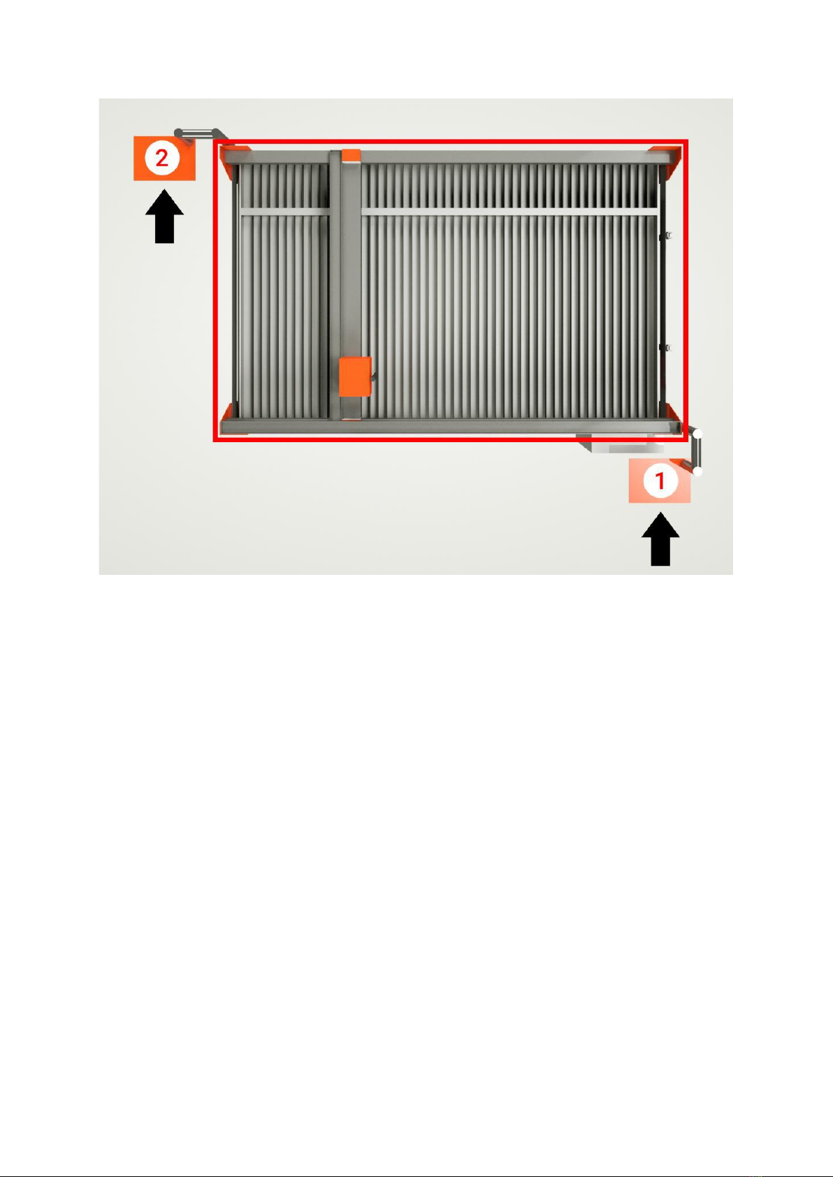
Working area. The correct position of operators outside the working zone
1. Main working area
2. An additional workplace for cutting profiles
3.8. POTENTIAL HAZARDS DURING PROCESS OF CUTTING WITH PLASMA BURNER OR GAS BURNER
CNC table is made to eliminate situations that are hazardous to health or life. Nevertheless, there
might be some hazards that will occur for the machine operator or bystanders.
When cutting with plasma and gas burners the following hazards might take place:
during cutting, the temperature of the torch flame exceeds several thousand °C
when cutting, there is a high radiation due to the burning of gases and the formation of an electric
arc
molten metal splinters may occur during piercing and cutting
gases and fumes are present during the cutting process
there is a risk of explosion when cutting with gas torches
3.8.1. HAZARDS THAT MIGHT BE CAUSED BY HIGH TEMPERATURE
The sources of high temperature that occur during the cutting process may come from:
burner flame
high burner temperature
hot sheet metal element
sparks and metal spatters
liquid drop of the cutting element
cracked gas hoses
The effect of high temperature can be:

skin burn - complete destruction of the scarfskin
deep burn - destruction of a part of the skin along with sebaceous glands
total burn - complete destruction of the skin
Means of protection against the hazards mentioned above are:
wearing of protective clothing marked as flame-retardant. These are gloves, a leather apron,
protective footwear, a hat as well as face and eye protection.
using of manual or mechanical methods of loading/unloading a hot material to protect the
operator against high temperature;
protecting the operator's eyes by using special protective glasses with a darkness level of min. 6
DIN.
3.8.2 HAZARDS THAT MIGHT BE CAUSED BY SPARKS AND SPLITS
During cutting and piercing, sparks or splinters are produced which can cause burns or a fire.
As a means of protection against spatters you should:
use protective clothing marked as flame-retardant. These are gloves, a leather apron, protective
footwear, a hat, face and eye protection
not storing flammable substances near the device's working area
separate the work place with special protective curtains from other work stations
comply with fire regulations
ensure that the fire extinguisher is in place
3.8.3. HAZARDS THAT MIGHT BE CAUSED BY GASES AND SMOKES
When machine operator is exposed to the fumes generated during cutting process for a long time, it
might cause various diseases of the respiratory system. Dust comes into the human’s body mainly
through the respiratory tract. This way, to get into the body system, is used by very small particles
that pose the greatest threat to humans. A common feature of all industrial dusts is irritating effect
on upper respiratory tract of mucous membranes, e.g. iron oxides.
The effects of the above may be:
eye and skin irritation
nausea
metallic fever
headaches and dizziness
respiratory disorders
As a means of protection against gases and smoke you should:
ventilate the room in which the machine works
extract fumes and gases that were produced during the process
set the water level so that water comes into contact with the cutting material (applies to water
tables and plasma cutting)
control and do not exceed the max pollution values in the room where machine works
comply with all regulations regarding the operation of gas cylinders and gas cutting torches
3.8.4. RISK OF INFRARED, UV PROTECTION AND VISIBLE RADIATION
During plasma or gas cutting, there is a high radiation due to the burning of gases and the formation
of an electric arc.
The effects of radiation can be:
redness, damage to the scarfskin
faster ageing process
change of skin colour

allergies
burns
cancerous changes
damage, burns to the cornea, lens, retina, eye swelling, cataracts
loss of vision (when there is too much exposure to radiation)
stroke or heat exhaustion
As a means of protection against radiation:
protect the operator's eyes by using special protective glasses with a darkness level of at least 6 DIN
protect the operator's face by using a welding protective mask
use protective clothing that protects the operator against exposure to radiation
avoid looking directly at the burner flame
3.8.5. EXPLOSION HAZARD DURING CUTTING WITH A GAS BURNER
There is a risk of explosion when using a CNC machine with a gas burner and technical gases.
The explosion can be caused by:
oiled oxygen cylinders or welding equipment
overheated technical gas cylinder
oiled gas regulator during changing of cylinders
smoking in places where it is prohibited
using open fire in places where it is prohibited.
Hazards to the operator and bystanders due to the explosion:
heat burns
respiratory tract burns, respiratory problems
eye irritation
fainting
asphyxiation
injuries, injuries to limbs and head
limb amputation
death
Protection measures against explosion include:
strictly comply with applicable regulations regarding the use and storage of gas cylinders and the
installation of technical gases
cylinders must be placed vertically and secured from falling
in the event of damage to the installation, cylinders, regulators, hoses or other parts of the
installation it is absolutely necessary to terminate the work and inform the maintenance department
or the manager
use hoses, gas regulators and nozzles only for their intended purpose
do not use oil, grease in gas installations. All system components must be free of oil and grease
use explosion protection (e.g. fuses used on the burner and regulators)
carry out all work on the gas installation in accordance with applicable standards and by persons
having appropriate qualifications
shut off the gas supply after finishing work
If the machine is equipped in a plasma cutting device, detailed information on the rules of operation
and hazards during plasma cutting can be found in the operating instructions provided by the
manufacturer of the plasma source.

3.8.6. NOISE RISK
The equivalent sound pressure level at the workplace, corrected by the A characteristic, exceeds 70
dB (A) and is 83 dB (A). The final noise level during operation depends on many factors, including the
dimensions and grade of the material.
The equivalent sound pressure level at the workplace, corrected by the characteristics of A, does not
exceed 85 dB (A).
Hazards to the operator and bystanders due to noise:
Noise Level
Body reaction
to 70dB
Negative changes in the body
Over 70dB
Diseases
- hypertension
- stomach disorder
- increase of adrenaline in the body
to 90dB
Hearing impairment and hearing loss over time
Over 120dB
Possible mechanical damage to the hearing
130dB
Pain limit
To protect your hearing, use:
protective earphones
anti-noise plugs
3.9. SAFETY DEVICES AND ELECTRIC SHOCK PROTECTION
In the event of danger, the machine can be turned off using the EMERGENCY STOP button. This
button is located on the control panel
Electrical controls are placed in an electrical cabinet
The plasma burner is protected by sensors limiting the work area in the X-, X+, Y-, Y+ axes,
respectively. Modifications, alterations or damages to elements limiting the work area may result in
damage to the device. That is also a hazard of life or health loss for people standing nearby.

CNC table scheme
1. Working machine head
2. Top-up valve (opens and closes the reservoir tank after switching on or off respectively)
3. Coolant drain valve (for retention tank)
4. Plasma torch
5. Pump
6. Retention tank
7. Plotter bar Y axis
8. Adjustable bases for leveling the machine
9. Control panel with a computer
10. Start/Power switch
11. 230V AC socket supplying the computer
12. Main switch
13. Emergency stop switch
14. Y- limit switch
15. X+ limit switch (X- switch at the other end of the running rail)
16. Z+/Z- limit switch
17. Y + limit switch
3.10. ELECTRICAL SAFETY DURING STANDARD OPERATION
When operating the machine, follow the rules and guidelines below:
before starting work, the operator should check the technical condition of the machine by visual
inspection, in particular, the condition of guards, fastening elements and general condition of the
electrical installation
if the operator finds out that the machine is out of order, he should immediately secure it from
starting it up and notify maintenance department or manager
there must not be unnecessary items or tools on the numerically controlled table and control
cabinet
only use original consumable parts for work

spare parts must only be installed and removed with the safety switch off
load and work only with material dimensions specified in the TECHNICAL DATA chapter
all adjustment activities should be carried out after disconnection of the main switch. Such
activities must be supervised by a second person who could help if necessary
it is not allowed to manually or mechanically remove waste materials while plasma burner is
performing a cutting process. Clean the machine after switching off the power supply
while the machine is working, only the operator controlling the burner may be at the operating
position
inspections and repairs are the responsibility of the maintenance team. The operator cannot
perform such activities
Responsibilities of the machine operator are:
compliance with safe working methods given in the manual and provided by the manager or
foreman as a part of the instruction
ensuring good technical condition of the burner and its full efficiency
cleaning the table and linear guides after finishing work
ensuring the disconnection from the power supply after work
protection against starting up by unauthorized persons
3.11. DANGER OF ELECTRIC SHOCK
The burner should be connected to a power supply equipped with a switch that protects against
electric shock. The table structure should be connected to the grounding installation of the building
by PE wire (minimum 16 mm2). Work on the electrical installation may only be carried out by an
authorized and qualified electrician with qualifications for the use of electrical equipment and
installations of up to 1 kV. It is not allowed to change the settings of electrical devices. If electrical
work requires voltage to be turned on, a second person must help to turn on and off the power if
necessary. During repairs, adjustments or maintenance operations, the machine must be absolutely
stopped and secured in such a way that it cannot be accidentally started. At least once a year the
burner should be brought under electrical tests for electric shock protection. Once all tests are
completed, the relevant approval report has to be issued. The plasma burner must be definitely
connected to the grounding installation of the object in which it was installed via a protective
conductor. In the case of a "water" table, the burner must absolutely work above the surface of the
liquid. In case of burner having contact with water, this can result in electric shock and injuries to the
operator.
3.12. PROTECTION OF ELECTRICAL INSTALATION AGAINST HIGH VOLTAGE
It is the user's responsibility to protect the electrical installation system, to which the machine is
connected, from accidental over-voltages that may damage the machine's control parts. Damages to
the machine's control units caused by temporary surges and over-voltages will not be repaired under
the warranty. In such a case, the warranty will be voided by the manufacturer. The plasma burner as
a computer-controlled numerical device should be protected by an uninterruptible power supply
(UPS) with a minimum power of 1000W.
3.13. ELECTROMAGNETIC FIELDS (EMF)
Electric current flowing through any conductor creates locally electric and magnetic fields (EMF -
electromagnetic field). To reduce the danger associated with the EMF fields:
never wrap the body with torch wires
do not stand between burner wires

keep both hoses on one side of your body.
the return hose should be connected as close as possible to the place where the cutting process is
carried out
do not work, sit or lean on the plasma generator while it is operating
DANGER: The electromagnetic field (EMF) generated during plasma cutting can interfere with the
functioning of medical implants, e.g. a cardiac stimulator or hearing aid. People with medical
implants, e.g. a pacemaker, are required to consult a doctor before starting work, and take special
care. It is forbidden to stay near the place where the plasma cutting process is carried out without
consultation with an expert.
4. TRANSPORT AND STORAGE
During transport, the machine can be partially dismantled into:
CNC table
control cabinet
cutter bar
During the road transport, the machine must be secured (e.g. with wedges, belts) so that it does not
move. When handling the machine, anybody must not be under a lifted load. The forks of the forklift
must be set to the max position when unloading. The crossbar should be set in a position close to the
middle and secured against possible displacement. Pay special attention to avoid damaging the tank
and hydraulic hoses inside the device when using the forklift.
4.1. EXTERNAL DIMENSIONS AND WEIGHT
SPARTUS Pro CUT HD 2050
length x width x height: 2550 x 2000 x 130 mm
weight: ~ 700 - 800 kg
SPARTUS Pro CUT HD 2550
length x width x height: 3050 x 2200 x 130 mm
weight: ~ 900 - 1,000 kg
SPARTUS Pro CUT HD 3050
length x width x height: 3550 x 2400 x 130 mm
weight: ~ 1,200 - 1,350 kg
4.2. PACKAGE
The device is not wrapped up. It is not protected against rain. Means of transport and storage must
protect machine against weather conditions.
4.3. INSPECTION ON RECEPTION
In the event of deficiencies in delivery, the recipient must fill up a relevant document stating these
deficiencies and provide to the seller.
4.4. STORAGE
The machine is preserved and can be stored in a dry room for 3 months. It can stand without
restrictions in a heated room.

5. SETTING UP, INSTALLATION, STARTING
5.1. INSTALLATION AND SETTING UP THE MACHINE
The machine should be placed on a horizontal foundation or floor. It must be levelled. There are
leveling screws at the ends of the legs for height adjustment. When inserting and screwing, the
raised loads must be firmly supported. Connecting cables must not be a tripping hazard. Electrical
cables (including control cables disconnected for transport) are connected in a junction box in
accordance with relevant numbering.
Location of regulatory and leveling feet
5.2. CLEANING
The metallic table surfaces are coated with an anti-corrosion agent. Before startup, wipe them dry.
5.3. CONNECTION OF ELECTRICITY
This work can only be carried out by an authorized electrician in the field of operating electrical
equipment and installations up to 1 kV. Connection parameters are described in the TECHNICAL
DATA chapter. Before connecting machine to the network, it is recommended to check the insulation
resistance, which should not exceed 1 MV. When the machine has stood for more than 15 days in an
unheated room, a check is necessary. A machine with damp insulation should be dried and the
insulation resistance checked again.
5.4. CONNECTION OF VENTILATION (applies to sectional table)
The ventilation duct is located at the back-right part of the CNC table. The filtering device must
provide a capacity of approx. 3000 m3/h. It is forbidden to use a filter fan when machining aluminum
alloys, the resulting magnesium dust may be accumulated in the filter cartridges and that may cause
an explosion hazard.

5.5. WATER TABLE
The use of a water table makes it possible to significantly reduce the deformation of cut materials,
especially with small thicknesses such as 0.5 - 3 mm. It also reduces noise generated during the
cutting process as well as smoke and radiation. Remember that the used coolant has to be
utilised/recycled. The manufacturer recommends using a corrosion inhibitor solution liquid to
protect the metal parts of the machine against corrosion.
6. WORKING PROCESS
6.1. START-UP, WORKING CYCLE
When the machine is adjusted, the order of startup is as follows:
1. Turn on the main switch.
2. Turn on the power of the plasma cutter with the switch on the control panel.
3. Turn on the power to the plasma generator.
4. Start the CNC control program.
Work in a cycle always starts with putting a metal sheet on the table.
6.2. MACHINE RECONFIGURATION
Replacing the torch to cut a material with different thickness:
1. Turn the machine off with the main switch.
2. Turn off the power to the plasma generator.
3. Remove the plasma / gas torch.
4. Install the plasma / gas torch.
6.3. SHUTDOWN DURING TYPICAL OPERATION AND EMERGENCY
6.3.1. STANDARD SHUTDOWN
At the end of the cycle or during operation, it is possible to stop the machine with the "STOP" button
on the control panel or the "STOP" virtual key in the computer program.
6.3.2. EMERGENCY STOP
In an emergency, you can stop the machine at any time with the EMERGENCY STOP switch located on
the control panel.
6.4. CONTINUATION OF WORK AFTER EMERGENCY STOP OR FAULT
If, in an emergency, the machine was stopped by an emergency switch, first you need to remove the
cause of the hazard. To unlock the EMERGENCY STOP button turn it to the right.
Resetting the cutting program stops the machine. After restarting the program and confirming it on
the operator panel, the machine continues the cycle.
6.5. INTERFERENCE AT WORK, FAULTS
The cycle may stop, e.g. when the torch support is too close to the extreme positions of the CNC
table. It also stops due to torch contact with the metal sheet detected by the collision system (arc
breaking during the cutting process or for other reasons not described). Interference affecting the
operation of the CNC table may arise when the device is connected to a plasma source in which
ignition occurred by using high frequency (HF). This frequency strongly affects the electronic
components of the CNC table and in extreme cases may cause their damage. To eliminate the effects

of high frequency:
ground the machine structure with a PE wire min. 16mm2 with the electrical grounding point no
further than 6m from the device
ground the plasma source with a PE cable min. 16mm2 with the electrical grounding point not
further than 6m from the device
ground the head support in which the plasma source burner is located
apply the so-called EMC braid over the entire length of the plasma torch, connecting it to the
grounding of the electrical system
The procedures and methods presented above may not be effective whenever RFI / EMI interference
suppression is required. The final way to implement these solutions may depend on the plasma
source being installed. However, they should be used consistently for all models of the selected
group.
In the event of high levels of interference, it is recommended that the torch lead should be at a
minimum distance of 150 mm from other electrical cables.
7. MAINTENANCE
Failure to follow the lubrication and maintenance regulations for the plasma CNC may cause
equipment failure. If the users are found out that they do not comply with the guidelines included in
the documentation, the manufacturer reserves the right to make a paid repair excluding the
warranty conditions.
7.1 PERIODIC GREASING
toothed bar
Z axis ball screw
- Every day before starting and after finishing work - wipe the linear guides of X and Y axis with a dry
cloth, clean the table surface from waste materials remaining after the device's work. Lack of
systematic wiping off linear guides will result in premature corrosion of drive components and
damage to linear trolleys of the device. In practice, properly maintained elements mentioned above
will help the machine to reach a lifetime service of 12-18 months during the production process
whereas improper maintenance or lack of service will decrease that to 5-6 months.
- Maintenance once a week - the linear guides should be greased once a week with machine oil or
other oil specified by the manufacturer. For this purpose, the guides should be wiped dry with a
clean cloth, greased with an appropriate agent. Then make a few complete rides from the beginning
to the end of each axis. Usually three or four passes are sufficient. After these operations, wipe off
excess of oil from the guides. The lack of systematic maintenance of the X-axis and the Y-axis linear
guides may result in premature corrosion. The bar and gears should be cleaned with a wire brush or
compressed air at least once in every 7 days. After cleaning, a small amount of grease should be
applied to the bar and gear. Excess of grease should be removed with a cloth.
All maintenance operations must be carried out with the main switch turned off.
7.2 REMOVAL AND DISPOSAL
During scraping, aluminum scrap (pneumatic components) must be separated from steel scrap.
Pneumatic hoses made of polypropylene are utilized as plastics. The wiring and engine coils are
considered as copper scrap.

7.3 SERVICE
The manufacturer provides a 12-month warranty. Minor post-warranty repairs may be carried out by
the user only after consulting the manufacturer. If necessary, the manufacturer send spare parts
which were ordered. Major post-warranty repairs should be performed by the manufacturer or an
authorized service center.
8. LIST OF SPARE PARTS
8.1. LIST OF SPARE PARTS THAT WEAR OUT QUICKLY
Torch components such as electrode nozzles, caps, shields
8.2. DAILY SERVICE LIST OF ACTIONS BEFORE STARTING WORK
inspect the technical condition of the machine, check that all the components are ready for work
visually inspect the condition of electrical wiring, gas and air lines
in the event of any faults, they must be rectified before putting the machine into operation
wipe the linear guides of the X and Y axis with a dry cloth
These activities must be carried out with the device powered off
8.3. DAILY MAINTENANCE LIST OF ACTIONS AFTER ENDING WORK
clean spatters and dust off the burner with a dry cloth
use the compressed air to blow out dust and spatters from the X- and Y-axis gears
check and clean the burner consumables, replace them if necessary.
9. PERIODIC SERVICE
Tank and table cleaning, depending on the intensity of use.
Greasing of the ball screw of Z axis in every 20 hours of operation.
IT IS FORBIDDEN TO CARRIED OUT A WELDING PROCESS OR GRINDING WORKS "ON THE MACHINE"
OR NEARBY. THIS COULD DAMAGE THE CONTROLLER, FOR WHICH THE MANUFACTURER IS NOT
RESPONSIBLE. THE WARRANTY COULD BE VOID AS WELL.
Table of contents


