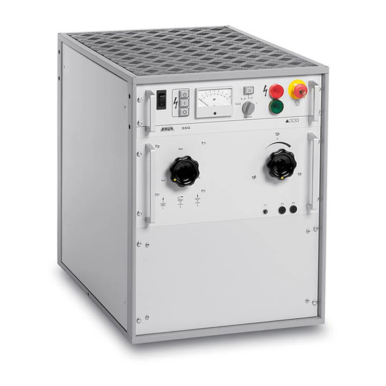
SPE CO1-2 User manual

CO1-2
4KW COMBINER
1.8 –54 MHz
USER MANUAL
Rev. 1.1

User Manual
CO1-2 Combiner
INDICE Page 2 of 36
Index
IMPORTANT ......................................................................................................................................................3
HOW TO READ THIS MANUAL ........................................................................................................................3
PRECAUTIONS..................................................................................................................................................4
UNPACKING ......................................................................................................................................................6
1. PANEL DESCRIPTION...............................................................................................................................7
1.1 Front Panel...........................................................................................................................................7
1.2 Rear Panel. ..........................................................................................................................................8
2. GENERAL INFORMATION.........................................................................................................................9
2.1 Power supply........................................................................................................................................9
2.2 External Ground Connection (Gnd)......................................................................................................9
2.3 Kit Cables (option)................................................................................................................................9
2.4 “PORT IN” Connector.........................................................................................................................10
2.5 “PORT OUT” Connector.....................................................................................................................11
2.6 “REMOTE” Connector. .......................................................................................................................12
2.7 Alarms. ...............................................................................................................................................13
3. USE OF THE COMBINER ........................................................................................................................14
3.1 Block Diagram....................................................................................................................................14
3.2 Interconnection with NON Expert Amplifiers......................................................................................15
3.3 Interconnection WITH Expert Amplifiers. ..........................................................................................16
Connection with one transceiver. ...................................................................................................16
Connection with two transceivers...................................................................................................18
3.4 PORT Cable.......................................................................................................................................20
3.5 CAT Cable..........................................................................................................................................21
3.6 CAT, ALC, PTT cables without PC. ...................................................................................................23
PTT, ALC, CAT RS 232 cables......................................................................................................24
PTT, ALC, CAT TTL Yaesu cables. ...............................................................................................24
PTT, ALC, CAT TTL Kenwood cables............................................................................................25
PTT, ALC, CAT BAND DATA cables. ............................................................................................25
3.7 CAT, ALC, PTT cables with PC. ........................................................................................................26
PTT, ALC, CAT Icom CI-V cables..................................................................................................26
PTT, ALC, CAT RS 232 cables......................................................................................................27
PTT, ALC, CAT TTL Kenwood cables............................................................................................28
4. INITIAL OPERATION................................................................................................................................29
4.1 Synchronization of the Amplifiers.......................................................................................................29
4.2 Set-up of the ATU...............................................................................................................................30
5. MAINTENANCE ........................................................................................................................................31
6. REMOTE CONTROL OF THE AMPLIFIERS............................................................................................32
6.1 Computer Connection. .......................................................................................................................33
6.2 Selective Addressing..........................................................................................................................33
7. WARRANTY TERM...................................................................................................................................35

User Manual
CO1-2 Combiner
INDICE Page 3 of 36
We congratulate you on the choice of the Combiner CO1-2.
With this device you can add the power of two linear amplifiers, even those not
produced by SPE.
It is recommended that amplifiers not produced by SPE are as equal to each other
as possible to avoid that the strong difference in power between the two is
dissipated by the balancing resistance contained in the Combiner itself.
In regards to SPE production amplifiers, thanks to the unique use of ALC, the
difference in output of the two amplifiers is automatically reduced to the
minimum (the highest output is reduced to approximately the same output as the
less powerful amplifier) in order to make the dissipation of the balancing
resistance insignificant.
In addition, all Expert amplifiers retain their characteristics such as CAT control,
use of the internal ATU, and the ability to select up to six antennas (see chapter
3.3).
The Combiner CO1-2 optimizes the investment of the station as it allows the
increase of the power in successive steps whilst still maintaining the two
separate amplifiers available for DXpeditions or field days.
The device is not managed by software, so no upgrading will ever be necessary.
IMPORTANT
Before installing and using the equipment, we recommend that you read the
instructions in this manual carefully.
Failure to follow these instructions will result in voiding the warranty.
Keep the manual, it contains important information regarding the safety and
correct use of the Combiner.
HOW TO READ THIS MANUAL
The manual can conceptually be divided into three parts:
• First part, from chap. 1 to chap.3.
Shows the main features of the CO1-2 and how to connect it.
• Second part, from chap. 4 to chap. 5.
Describes how to operate and maintain the CO1-2.
• Third part, chap. 6.
Describes the use of the software provided for remote control of the two Expert
amplifiers used.

User Manual
CO1-2 Combiner
INDICE Page 4 of 36
PRECAUTIONS
Explicit definitions
WORD
DEFINITION
WARNING!
Risk or danger of fire or electric shock to people.
Possible damage to the amplifier.
NOTE:
Serious problems if not observed. Danger of fire or electric shock for the operator,
or damage to the equipment.
WARNING!
DO NOT disconnect the coaxial cables when the device is in transmission mode.
This could cause a risk of electric shock or burns.
WARNING!
DO NOT modify the internal settings of the device. This could reduce the performance
of the Combiner or damage it.
WARNING!
Before powering up the device, check the value of the power supply which must be
compatible with the device.
WARNING!
DO NOT use the device, before you have connected it to the protective earth.
WARNING!
DO NOT allow metal objects or wires to penetrate inside the appliance.
WARNING!
DO NOT obstruct the front and rear air intakes of the unit.
ENSURE that no objects impede the correct functioning of the fans.
WARNING!
DO NOT expose the equipment to rain, snow or any liquid.
WARNING!
AVOID locations without adequate ventilation. Proper dissipation would be impeded
resulting in damage to the device.
WARNING!
DO NOT touch the device with wet or damp hands. This could cause electrocution.
DO NOT open the combiner without first disconnecting it from the devices connected to
it.

User Manual
CO1-2 Combiner
INDICE Page 5 of 36
To clean the Combiner DO NOT use chemical agents like alcohol or benzene, as the
plastic surfaces could be damaged.
AVOID using the Combiner in areas with temperatures below 0° C (+32°F) or above
+40°C (+104°F).
AVOID using the Combiner in locations that are very dusty, damp, have high humidity or
that are in direct sunlight.
AVOID placing the Combiner against walls where the circulation of the air would be
obstructed and the noise of the fans would be reflected toward the operator.
AVOID permitting children to play with the Combiner.
Information for Users on Collection and Disposal of Old Equipment and Used
Batteries.
These symbols on the products, packaging, and/or accompanying
documents mean that used electrical and electronic products and batteries
should not be mixed with general household waste.
For proper treatment, recovery and recycling of old products and used
batteries, please take them to the relevant collection points, in accordance
with your national and local legislation.
The use of the Combiner CO1-2 is allowed by operators with an adequate license.
Its installation and its use (power, band, transmission mode, etc.) must comply
with the current laws of the State in which it operates.
The Combiner is essentially passive and therefore does not require FCC
certification for radio amateur use (if required).
However, where such certification is required, it is essential that the linear
amplifiers used are FCC certified.

User Manual
CO1-2 Combiner
INDICE Page 6 of 36
UNPACKING
Remove the packaging and carefully check the contents.
If you find any damage, or if there are any parts missing, contact your distributor/dealer
immediately. It is recommended to keep the shipping cartons and packing materials for
future transportation.
Accessories included in the carton
a. Spare air filter.
b. 1 x Power Supply connector.
c. 1 x DB-9M connector.
d. 1 x DB-15M connector.
e. Kit: PORT Cable, CAT Cable, 2 x COMBINER Cables, 2 x SPLITTER Cables.
(option, see page 9)
f. CD-ROM containing the user manual and the software for remote use.
g. Warranty card.
h. 1A Fuse.
a b c d
e
f g h

User Manual
CO1-2 Combiner
INDICE Page 7 of 36
1. PANEL DESCRIPTION
1.1 Front Panel.
1) Led bar showing the output power.
2) Led bar of the power dissipated in the balancing resistor.
3) Alarm when 700 W imbalance is reached.
4) Led bar of the balancing resistance temperature.
5) Balancing resistance temperature alarm.
6) Hardware alarm or alarm of non-synchronism between the amplifiers.
7) Indicates that the Combiner is ON.
8) ON button.
9) Turns off the Combiner or Resets an Alarm.

User Manual
CO1-2 Combiner
INDICE Page 8 of 36
1.2 Rear Panel.
1) To be connected to the transmitting antenna or to the antenna switch (if in use).
2) To be connected to an amplifier output (COMBINER Cable).
3) To be connected to the output of the other amplifier (COMBINER Cable).
4) Fans.
5) To be connected to the input of an amplifier (SPLITTER Cable).
6) To be connected to the input of the other amplifier input (SPLITTER Cable).
7) To be connected to the antenna connector of the transceiver.
8) GND.
9) PORT OUT to control the Antenna Switch (if in use).
10) REMOTE for remote control (if in use).
11) PORT IN to be connected with the respective "PORT" of the two Expert
amplifiers for synchronization (PORT CABLE).
12) Device power supply (13.8V DC, 1A.).

User Manual
CO1-2 Combiner
INDICE Page 9 of 36
2. GENERAL INFORMATION
2.1 Power supply.
The Combiner is powered by an external source of 13.8 V DC nominal (15.5 V DC
max).
Considering the low current required (1 A max.), the transceiver power supply can be
used.
This voltage is shown on the "PORT OUT" connector in order to supply the antenna
switch (optional).
There is a slow 1 A fuse inside the Combiner.
2.2 External Ground Connection (Gnd).
WARNING! Before connecting an external ground as described below, check with
a qualified electrician that your national wiring codes a connection.
To reduce TVI, BCI and other RF problems it is best to connect the amplifier to a good
RF ground. (Note that an RF ground is different to an electrical ground which is
necessary for the prevention of electrical shock).
The inductance of such a connection needs to be low, so the connection to ground
should be as short and direct as possible.
Large-section copper conductors should be used for this purpose.
It is recommended to terminate the earth connection with a small metal plate.
The best solution is to have several ground stakes, driven into the ground, and these
ground stakes also need to be tied to your main grounds.
Good results can often be achieved by using correct earthing clamps, connected to the
main water supply pipe (note, many water pipes are now made out of plastic).
DO NOT use central heating pipe work.
AVOID the electric circuit ground of the building (to be used for 50/60 Hz safety only).
WARNING! DO NOT connect to gas pipes as there will be a danger of
explosion!!
2.3 Kit Cables (option).
A cable kit can be provided to connect between the two amplifiers and the Combiner;
each cable is long enough to place the three devices stacked or side by side.
For other provisions involving longer lengths refer to the chapters below.
The Kit consists of n. 6 cables (see page 6):
n.1 PORT Cable, n.1 CAT Cable, n. 2 x COMBINER Cable, n. 2 x SPLITTER Cable.
The CAT Cable, for construction reasons, is supplied in two versions to choose from
when ordering:
CAT Cable / CAT for connection to all CATs.
CAT Cable / Band Data for the "BAND DATA" connection.

User Manual
CO1-2 Combiner
INDICE Page 10 of 36
2.4 “PORT IN” Connector.
If you use two EXPERT amplifiers from this connector, use a Y-cable to interconnect the
"PORT" connector of each amplifier.
This allows the synchronization of the two amplifiers; if not, an alarm will occur.
The two amplifiers are synchronized when their settings are perfectly identical, therefore
this cable is necessary in order for the Combiner to function properly.
This connector is not used with non-Expert amplifiers.
Pin
Number
Pin Name
Description
1
+ 12 V DC_1
Present when amplifier 1 is ON (input).
6
+ 12 V DC_2
Present when amplifier 2 is ON (input).
2
GND
GND.
7
BIT A_1
BIT A of the antenna set in amplifier 1.
3
BIT A_2
BIT A of the antenna set in amplifier 2.
8
BIT B_1
BIT B of the antenna set in amplifier 1.
4
BIT B_2
BIT B of the antenna set in amplifier 2.
9
BIT C_1
BIT C of the antenna set in amplifier 1.
5
BIT C_2
BIT C of the antenna set in amplifier 2.

User Manual
CO1-2 Combiner
INDICE Page 11 of 36
2.5 “PORT OUT” Connector.
If two Expert amplifiers are used, this connector provides information in BCD open
collector of the antenna set on the two synchronized amplifiers, a 13.8 V DC source is
also available to power the Antenna Switch (if present).
This connector is not used with non-Expert amplifiers, if you have an external manual
switch, or a single antenna.
Pin
Number
Pin Name
Description
1
BIT A
BIT A relates to the number of the antenna in use (open collector).
6
BIT B
BIT B relates to the number of the antenna in use (open collector).
9
BIT C
BIT C relates to the number of the antenna in use (open collector).
5
GND
GND.
2
NC
3
NC
7
NC
8
NC
4
+ 13.8 V DC
+ 13.8 V DC, to power the Antenna Switch, 0.25 A Max.

User Manual
CO1-2 Combiner
INDICE Page 12 of 36
2.6 “REMOTE” Connector.
This connector allows remote control of the Combiner by making the terminals for the
"ON", "OFF / RESET" keys and all the alarms on metal contact and open collector (40 V
100 mA max.) available to the user.
Pin
Number
Pin Name
Description
1
+13.8 V DC
To supply power to an external device, 0.2 A max.
9
GND
GND.
2
COM
Relay contacts to indicate the ON status.
10
N.C.
3
N.O.
11
COM
Relay contacts to indicate the Alarm status (generic).
4
N.C.
12
N.O.
5
ON
Button or external contact for ON function
13
ON
6
OFF / RESET
Button or external contact for OFF / RESET function
14
OFF / RESET
7
AL HW
Synchronization alarm (open collector)
15
AL UNBAL
Unbalance alarm between amplifiers (open collector).
8
AL TEMP
Temperature alarm (open collector).

User Manual
CO1-2 Combiner
INDICE Page 13 of 36
2.7 Alarms.
All alarms are highlighted with optical and acoustic indication and repeated in the
"REMOTE" connector.
When an alarm occurs, the Combiner stops working immediately, and the transceiver is
connected to an internal 250W dummy load as a precaution.
After alleviating the problem, press the "OFF / RESET" key to restore operation.

User Manual
CO1-2 Combiner
INDICE Page 14 of 36
3. USE OF THE COMBINER
3.1 Block Diagram.
Because of the simplified structure there is no RF switching, and therefore it is not
necessary to connect to the PTT of the transceiver.
The essential part of the Combiner contains exclusively passive elements; active
components are only used in the interfaces (see previous chapter).

User Manual
CO1-2 Combiner
INDICE Page 15 of 36
3.2 Interconnection with NON Expert Amplifiers.
With reference to the previous diagram:
1. Connect the transceiver output to the XMTR connector.
2. Connect the ANTENNA connector to the antenna in use.
3. Connect the amplifier inputs with the SPLITTER out 1 and out 2 connectors.
WARNING: it is absolutely necessary that the two cables are of exactly equal lengths
and are of the same make and model.
4. Connect the amplifier outputs to the COMBINER connectors 1 and 2.
WARNING: it is absolutely necessary that the two cables are of exactly equal lengths
and are of the same make and model.
Use cables that are suitable for adequately handling the power involved.
The GND and 13.8 V DC connections must also be made.
The "PORT IN" and "PORT OUT" connectors must not be used.
ATTENTION: When using non-Expert amplifiers, it is recommended that the two
amplifiers are set so that they generate the most equal power out.
This can be achieved by minimizing the indication of the LED bar of the power
dissipated in the balancing resistor (800 W max.).
It would be a good idea to separately tune each amplifier to the antenna, and then
connect it to the Combiner.

User Manual
CO1-2 Combiner
INDICE Page 16 of 36
3.3 Interconnection WITH Expert Amplifiers.
Connection with one transceiver.
The connection diagram between Combiner and two Expert 1.3K-FA or two Expert
1.3K-FA is shown.
For the connection with two Expert 2K-FA or two Expert 1K-FA refer also to chapter 4.1.

User Manual
CO1-2 Combiner
INDICE Page 18 of 36
1. Connect the transceiver output to the XMTR connector.
2. Connect the ANTENNA connector to the antenna in use or the Antenna Switch.
3. Connect the amplifier inputs with the SPLITTER out 1 and out 2 connectors using
the two "SPLITTER cables".
WARNING: If the distances of use are greater, it is absolutely necessary that the
two new cables are of exactly equal lengths and are of the same make and
model.
4. Connect the outputs of the amplifiers with the COMBINER connectors in 1 and in
2 using the two "COMBINER cables".
WARNING: If the distances of use are greater, it is absolutely necessary that the
two new cables are of exactly equal lengths and are of the same make and
model.
Use cables that are suitable for adequately handling the power involved.
5. Connect the "PORT IN" of the Combiner with the "PORT Cable" to each "PORT"
of the two Experts (if the distances of use are greater, see chapter 3.4).
6. Connect the "CAT1" connectors of each Expert with the CAT, ALC and PTT
outputs of the transceiver with the "CAT Cable" (if the distances of use are
greater, see chapter 3.5).
The old CAT cable which originally interfaced only to one amplifier can be
connected directly to the extension of the supplied Y cable (connector DB-15F).
If there are also cables with RCA connectors, just keep their existing connection
with one of the two amplifiers.
This solution makes installation very easy and quick.
In the absence of a previous installation (old CAT cable missing), it is necessary
to build a new cable, the following two options are possible:
a) For connection with the transceiver only (see chapter 3.6).
b) For connection with the transceiver and a PC (see chapter 3.7).
The GND and 13.8 V DC connections must also be made.
The connection to the "PORT OUT" is to be used only in presence of the remote
antenna switch "AMB-01-PW" with the ability to remotely select the 6 antennas set in
the Expert.
Refer to the Amplifier and Switch manual "AMB-01-PW".
Connection with two transceivers.
It is also foreseen the use of two transceivers that can be switched between them with
the simple intervention of the respective PTT (see amplifier manual).
In the diagram the differences with the previous one with only one TRX are highlighted
in red.
It is only necessary to add 2 JUMPER cables (which must be strictly the same length)
and another CAT Cable for the TRX2.
The CAT Cable is identical to the one supplied in the Cable Kit.
The two JUMPER cables and the CAT Cable can be ordered or easily built using the
instructions in this manual.

User Manual
CO1-2 Combiner
INDICE Page 19 of 36
The RTX antenna switch can be controlled via the AUX connector of either the first or of
the second amplifier taking the +12 Vdc. (pin.15) and EN2 (pin.12).
Since EN2 is an open collector, if you decide not to use the 12 Vdc provided by the
linear, it is advisable not to exceed 40 Vdc, 80 mA.
In any other case, use a servo-relay.
The use of a diode in parallel with the relay coil is mandatory.

User Manual
CO1-2 Combiner
INDICE Page 20 of 36
3.4 PORT Cable.
Connection cable between "PORT IN" and the "PORT" of the Expert amplifiers.
This cable is essential when using two Expert amplifiers (see point 5 of the previous
paragraph).
If the distances between the amplifiers and the Combiner are greater than the standard
cable length, you can proceed as follows:
a) Build an extension for the part of the cable to be extended.
b) Build a new cable with the right lengths.
All according to the following diagram.
Table of contents
Popular Portable Generator manuals by other brands
Hyundai
Hyundai STG1000 instruction manual
Briggs & Stratton
Briggs & Stratton 30426 Wiring Diagram & Schematic
Westinghouse
Westinghouse WGEN5300DFC user manual
Winco
Winco HPS6000HE/I Installation and operator's manual
Huazheng
Huazheng HZZGF-Z Series manual
LZX Industries
LZX Industries Cadet Series owner's manual

