Specialised Welding Products MIG 160 User manual
INSTRUCTION MANUAL
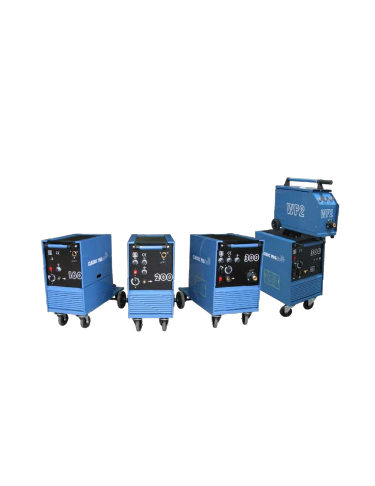
MIG 160 / MIG 200 / MIG 300 / MIG 300S

CONTENTS
WARNING
INSTALLATION
OPERATION
WELDING PARAMETERS
TROUBLESHOOTING
WARRANTY
SPARE PARTS LIST
TORCH CONSUMABLE LIST
3
4
5
6
7
8
8
9-10
2
EC DECLARATION OF CONFORMITY
Trakis Nagykoros Kft declares that the following machines:
Classic MIG 160 / 200 / 300 / 300S
Blue Brand MIG 160 / 200 / 300 /300S
correspond to the following edicts and standards:
MSZ EN 60974-1:2006 - IEC 60974-1:2005
MSZ EN 60204-1:2001 - IEC 60204-1:1997

3
Fume
Welding vaporises metals, and anything that is resting on the surface. This gives rise to
fume, which is condensed find particulate material. The fume is mostly oxides of the metals,
including any alloying elements, but it also contains gases produced in the arc, such as
ozone or oxides of nitrogen, and decomposition products from any paints or coating which
was on the metal surface. The nature and quantity of this fume depends critically upon the
welding process, the materials and the welding parameters. Some is harmful to health, for
instance stainless steel fume contains chromium, and welding galvanised steel produces
zinc fume.
Effects can vary from a bout of ‘metal fume fever’ to longer term, more serious problems if
suitable fume removal is not carried out. There is guidance literature that may be consulted
regarding the safe levels for each constituent, and the employer needs to be aware that for
some fume constituents, there may be no safe level, and a statutory exposure limit may be
imposed. Nickel, cobalt and stainless steel welding fume are the subject of statutory limits
in the UK. Highly efficient exhaust apparatus is available. Some health surveillance may be
necessary.
Noise
Welding environments are frequently noisy as other operations such as grinding, etc. may
also be taking place. Some operations, such as de-slagging may take the noise up to such
a level where it will damage workers hearing. In such cases this would mean that hearing
protection is almost certainly required if the noise cannot be controlled by other means.
Some health surveillance may also be necessary. To protect UK workers new noise exposure
limits are due to become law during 2006 and will represent a significant lowering of
statutory noise action levels which are currently set at 85dB(A) and 90dB(A) respectively.
Optical Radiation
The Welding process produces a large quantity of visible light, ultraviolet and infrared.
Exposure to the radiation from an arc causes burns to the skin, and damage to the eyes. For
this reason, welders need to wear clothing to protect their bodies and arms, regardless of
the weather conditions. They also need efficient eye protection, which is usually supplied in
the form of a protective shield. The precise choice of the shade of glass filter in these shields
depends on the type of welding operation, since they vary in their light output.
Welders assistants also need protective clothing and eye protection. Passers-by should be
protected by placing opaque or properly filtered screens around the work area.
Burns and Mechanical Hazards
Welders need good quality gloves, preferably leather gauntlets, safety boots or shoes and
good quality cap and overalls. A leather apron may also be needed. Welding produces
quantities of molten droplets of metal which are scattered in all directions. It is essential
that the welder wears clothing which will not burn or melt, and which is stout enough to
provide adequate protection.
WARNING

4
INSTALLATION
Electrical Connection
The migs comprise of three models, all single phase. Always ensure the machine is connected
to the correct supply, with the correct size of fuses or circuit breakers as shown below. If
circuit breakers are used they must be type four otherwise tripping may occur although
there is no machine fault.
Model Supply Type Fuse
160 MIG 240 volt single phase 20 Amp
200 MIG 240 volt single phase 20 Amp
300 MIG 240 volt single phase 40 Amp
300S MIG 240 volt single phase 40 Amp
Electrical Safety
Clearly, the employer needs to establish the level of competence of the electrician who is
given the task of wiring the installation, and the type of maintenance which the installation
and the equipment will subsequently need. In the UK there is a requirement for periodic
electrical checks to be done on power sources. The design of welding power sources
themselves has gone through a number of changes, and for each, there are different
standards of safety. The employer must ensure that his installation is correctly matched to
the type he is using - for instance double insulated power sources should not be used with
a separate earth lead to the workpiece.
Earth Connection
A suitable earth lead is supplied with the machine. The earth clamp must be securely
attached to the workpiece as a poor connection will affect the quality of the weld.
The machine is covered by a twelve month warranty but the main transformer and choke
are covered by a three year warranty. The warranty does not cover the torch and its
consumable parts. Please note if you require a service call by an engineer under warranty
and the problem is identified as operator fault or torch fault then you will be liable for the
charge encountered by the engineer. Please be sure to retain your receipt as this will be
required in the event of a claim.
WARRANTY

5
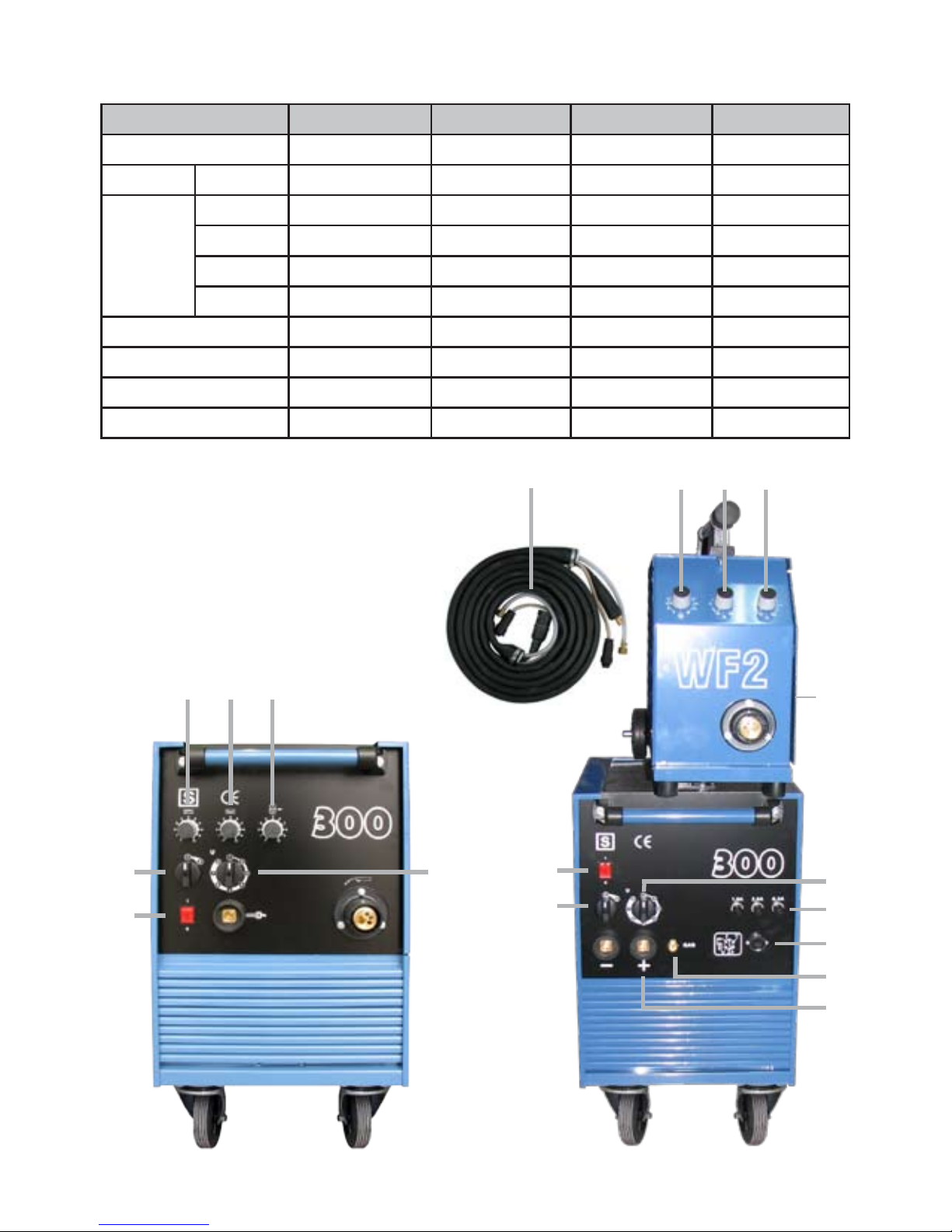
Controls
A On/Off Switch Is the illuminated rocker switch which lights up red when the
machine is switched on.
B Voltage Control 160 has six voltage settings 1 being the lowest.
Switch 200 has eight voltage settings 1 being the lowest.
C Voltage Control 300 / 300S the left-hand switch has two settings which alters
the
Switch voltage output in large steps, the right-hand switch has eight
settings which alters the voltage in small steps. Therefore 1-1 is
the lowest, 1-8 is intermediate and the maximum is 2-8 this
gives 16 voltage settings.
D Wire Speed Varies the wire speed between 2 and 20 metres per minute.
Control
E Weld Timer On models 200 and 300 only. This determines the amount of
welding time in the stitch and spot welding modes.
F Pause Timer On models 200 and 300 only. This determines the amount of no
weld time in the stitch welding mode.
G Fuses
H Wire Feed Connects to 300S by lead from WF2.
J Inter Connection 5m Standard, optional 10m.
Cable
OPERATION
A
B
DD
E F
A
B
6
Model MIG 160 MIG 200 MIG 300 / 300S WF2/ 4F2
Input 230v/50-60hz 230v/50-60hz 230v/50-60hz
Output Min 20A 22A 27A
Max 140A 200A 315A
35% 85A 150A 250A
60% 65A 120A 200A
100% 50A 92A 150A
Voltage Steps 6 8 16
Wire Size 0.6 - 0.8 mm 0.6-1.0 mm 0.6 - 1.2 mm 0.6 - 1.2 mm
Weight 65 kg 70 kg 92 kg 25 kg
Dimensions (LxWxH) 86 x 46 x 71 cm 85 x 46 x 71 cm 86 x 40 x 71 cm 56 x 22 x 40 cm
WELDING PARAMETERS
E F D
CC
A
E F
D
C
C
A
G
H
H
H
J
H

7
TROUBLESHOOTING
FAULT REASON REMEDY
Set is dead 1. On/Off switch is off Turn it on
2. Fuse in mains supply blown Replace fuse
Nothing happens when
torch trigger is pressed
1. Torch switch defective
2. Torch central connector pins not making
proper contact in the machine adaptor
Check for torch fault by shorting the
switch pin sockets on the central adaptor
and listening for the main contactor
coming in
3. Auxiliary circuit fuse blown Replace fuse
Wire is not conveyed
when feed roll is turning
1. The friction brake in the hub is
tightened too hard
Loosen
2. Insufficient pressure on drive roll Tighten
3. Wire is not running in the feed roll
grove
Re-align wire
4. Dirt in liner and/or contact tip Blow with compressed air, replace contact
tip
Wire feeding in jerks/
erratic
1. Contact tip worn/burnt Replace
2. Dirt in feed roll groove Clean and re-align wire
3. Groove of feed roll worn Replace
No arc 1. Bad contact between earth clamp and
workpiece
Tighten earth clamp and check connections
2. Short circuit between contact tip and
shroud
Clean replace tip/shroud as nececssary
Porous weld 1. Failure of Gas Shield Replace gas shroud check cylinder contents
2. Wrong distance and/or wrong
inclination of torch
The length of stick out wire from tip of
workpiece must be between 5-10mm
inclination not less than 60oin relation to
the workpiece
3. Too small qty. gas Increase gas flow
4. Draught Screen the weld area
5. Humid workpiece Dry workpiece
6. Heavily rusted workpiece Clean workpiece
7. Gas Solenoid defect Clean/Replace
Set suddenly stops 1. Machine overheated due to exceeding
duty cycle
Do not switch off, leave to cool down.
Machine will reset
Should any of these suggestions not remedy your fault contact your distributor in order to
facilitate service repair.

8
SPARE PARTS LIST
TRAKIS PART NUMBER DESCRIPTION MACHINE
W 9391 Potentiometer 10 KA 300 / 4F2
W 9392 Potentiometer 10 KB 160 / 200
W 9393 Potentiometer 470 KA 300 / 4F2
W 9394 ON/OFF switch 160 / 200 / 300 / 300S
W 9395 Reel Hub Assembly TRAKIS 160 / 200 / 300 / 4F2
W 9396 Hub Nut TRAKIS 160 / 200 / 300/ 4F2
W 9397 Gas Solenoid Valve 160 / 200 / 300 / 4F2
W 9398 Main Contactor DIL-K 410 160 / 200
W 9399 Main Contactor DIL-K 710 300 / 300S
W 9400 Wire Feeder Motor 24v 25w 160
W 9401 Wire Feeder Motor 24v 35w 200
W 9402 Wire Feeder Motor 24v 40w 300 / 4F2
W 9403 Printed Circuit Boards EB 102 160 / 200
W 9404 Printed Circuit Boards W-10 300 / 300S
W 9405 Feed Roll Ring 0.6-0.8 V 300
W 9406 Feed Rool Ring 1.0-1.2 V 300
W 9506 Feed Roll Ring 1.2-1.6 V 300
W 9507 Feed Roll Ring 0.6-0.8 V 160 / 200
W 9407 Feed Roll Ring 0.8-1.0 V 160 / 200
W 9408 Feed Roll Retainer Knob 160 / 200 / 300
W 9409 Capillary Tube 1.2 x 80 160 / 200
W 9410 Capillary Tube 2.0 x 97 300 / 4F2
W 9411 Combined Wire Feeder TRAKIS 160 / 200
W 9412 Fuse 5 x 20 1A 160
W 9413 Fuse 5 x 20 3.15A 160 / 200
W 9414 Fuse 5 x 20 6.3A 300 / 300S
W 9415 Fuse 6.3 x 32 1.6A 200 / 300 / 300S
W 9416 Cooling Fan 160 / 200
W 9417 Cooling Fan 300 / 300S
W 9418 Knob for Selector Switch 160 / 200 / 300 / 4F2
W 9419 Knob for Potentiometer 160 / 200 / 300 / 4F2
W 9505 Feed Roll Ring 0.6-0.8 V 4F2
W 9509 Feed Rool Ring 1.0-1.2 V 4F2
W 9510 Feed Roll Ring 1.2-1.6 V 4F2
W 9512 Feed Roll Retainer Knob 4F2
9381 Interconnecting Cable 5 mt. 4F2/ 300S
9382 Interconnecting Cable 10 mt. 4F2/ 300S

9
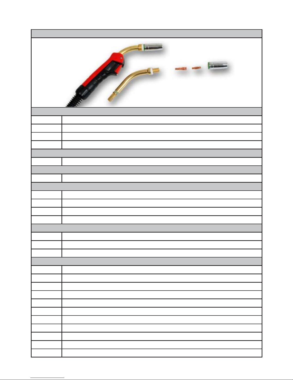
TORCH CONSUMABLE LIST
SWP 15 MIG TORCH & ACCESSORIES
SWP 15 MIG TORCH
CODE DESCRIPTION
6000 SWP 15 x 3 mtr Mig Torch - 002.0449
6001 SWP 15 x 4 mtr Mig Torch - 002.0450
SWAN NECKS
6033 Swan Neck - 002.0009
CONTACT TIPS
6567 0.6 mm Contact Tip - M6 Thread - 140.0008
6020 0.8 mm Contact Tip - M6 Thread - 140.0059
NOZZLES
6007 Conical Nozzle - 145.0075
6009 Tapered Nozzle - 145.0123
LINERS
6029 Steel Liner x 3 mtr 0.6 - 0.8 mm Wire - Blue - 124.0011
6030 Steel Liner x 4 mtr 0.6 - 0.8 mm Wire - Blue - 124.0012
6650 Teflon Liner x 3 mtr 0.6 - 0.8 mm - Blue - 124.0005
6651 Teflon Liner x 4 mtr 0.6 - 0.8 mm - Blue - 124.0008
6033
6567
6020
6007
6009
10
TORCH CONSUMABLE LIST (CONTINUED)
SWP 25 MIG TORCH & ACCESSORIES
SWP 25 MIG TORCH
CODE DESCRIPTION
6002 SWP 25 x 3 mtr Mig Torch - 004.0312
6003 SWP 25 x 4 mtr Mig Torch - 004.0313
6598 SWP 25 x 5 mtr Mig Torch - 004.0314
SWAN NECKS
6034 Swan Neck - 004.0012
TIP ADAPTORS
6023 Tip Adaptor for M6 Contact Tips - 142.0001
CONTACT TIPS
6568 0.6 mm Contact Tip - M6 Thread - 140.0005
6569 0.8 mm Contact Tip - M6 Thread - 140.0051
6021 1.0 mm Contact Tip - M6 Thread - 140.0242
6570 1.2 mm Contact Tip - M6 Thread - 140.0379
NOZZLES
6010 Conical Nozzle - 145.0076
6011 Cylindrical Nozzle - 145.0042
6012 Tapered Nozzle - 145.0124
LINERS
6029 Steel Liner x 3 mtr 0.6 - 0.8 mm Wire - Blue - 124.0011
6030 Steel Liner x 4 mtr 0.6 - 0.8 mm Wire - Blue - 124.0012
6657 Steel Liner x 5 mtr 0.6 - 0.8 mm Wire - Blue - 124.0015
6031 Steel Liner x 3 mtr 1.0 - 1.2 mm Wire - Red - 124.0026
6032 Steel Liner x 4 mtr 1.0 - 1.2 mm Wire - Red - 124.0031
6655 Steel Liner x 5 mtr 1.0 - 1.2 mm Wire - Red - 124.0035
6650 Teflon Liner x 3 mtr 0.6 - 0.8 mm Wire - Blue - 24A62
6651 Teflon Liner x 4 mtr 0.6 - 0.8 mm Wire - Blue - 126.008
6652 Teflon Liner x 3 mtr 1.0 - 1.2 mm Wire - Red - 126.0021
6653 Teflon Liner x 4 mtr 1.0 - 1.2 mm Wire - Red - 126.0026
6654 Teflon Liner x 5 mtr 1.0 - 1.2 mm Wire - Red - 126.0028
6034
6023 6568
6569
6021
6570
6010
6011
6012

Specialised Welding Products Ltd
14 Farringdon Industrial Centre
Farringdon, Nr Alton
Hampshire GU34 3DP
This manual suits for next models
3
Table of contents
Other Specialised Welding Products Welding System manuals

Popular Welding System manuals by other brands


Smoothcut
Smoothcut Plasma 100 operating manual

Telwin
Telwin INVERPULSE 320 MIG-TIG-MMA instruction manual

Ramsond
Ramsond CT Series instruction manual

Migatronic
Migatronic NAVIGATOR 2500 instruction manual

Lincoln Electric
Lincoln Electric INVERTEC V205-T AC/DC TIG Operator's manual

Lincoln Electric
Lincoln Electric OUTBACK SVM204-A Service manual