Spectronik CEREBRAL-55 User manual
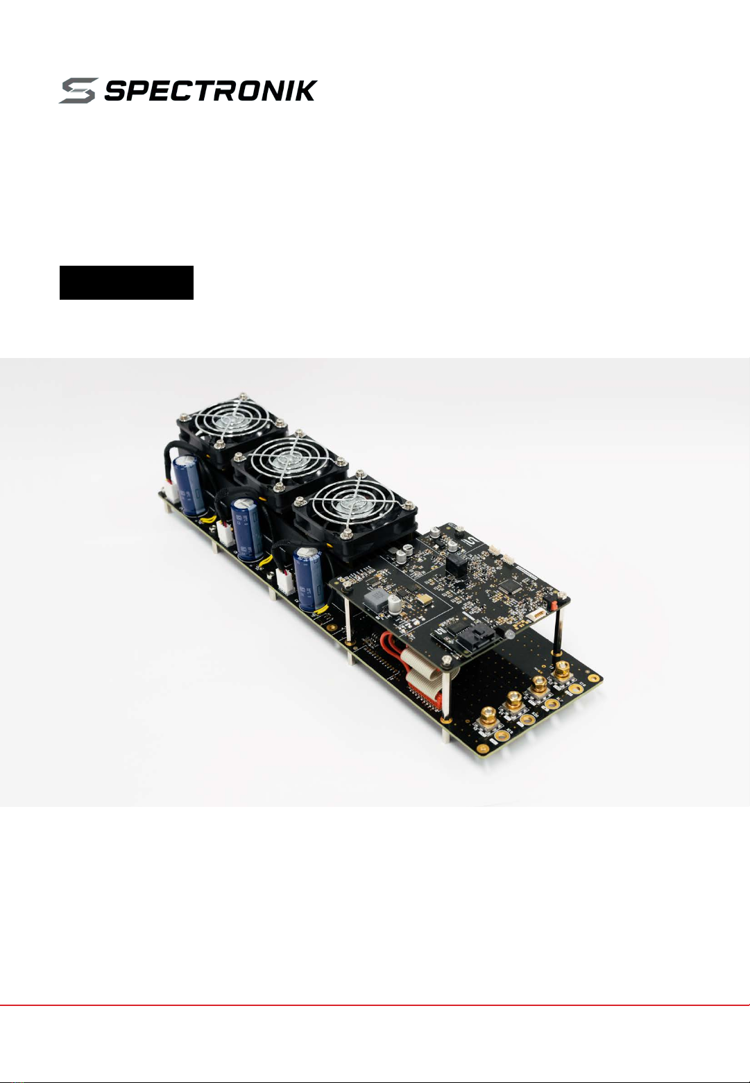
CEREBRAL-55
SMART DC-DC CONVERTER
USER GUIDE
VERSION 1.0 JUNE 2022

Failure to follow these safety instructions could result in fire, electric shock, other
injuries, or damage to CEREBRAL-55 Smart DC-DC Converter (CEREBRAL-55)or other property.
Read all the safety information below before using CEREBRAL-55.
Handling Handle CEREBRAL-55 with care.It comprises half-brick DC-DC converter modules, printed circuit
board, electronic components, heat sinks and cooling fans.CEREBRAL-55 is not designed for extreme conditions,
rough handling, vibration, shock or drop.Keep CEREBRAL-55 away from heat, flame, strong sunlight, water, dust,
soil or mud.Do not use adamaged CEREBRAL-55.
Repairing Do not disassemble or tamper with CEREBRAL-55.Do not troubleshoot, repair or replace any
component by yourself.
Ventilation Operate CEREBRAL-55 in awell ventilated environment.Hot air exiting from the cooling fans shall not
be obstructed or restricted.
Connectors, ports and buttons Never force a connector into a port or apply excessive pressure to a button. If
the connector and port do not join with reasonable ease, they probably do not match.Check for obstructions and
ensure that the connector matches the correct port.
Disposal and recycling As CEREBRAL-55 contains electronic components, it must be disposed of separately
from household waste.When CEREBRAL-55 reaches its end of life, follow local laws and regulations for proper
disposal and recycling options.
High-consequence activities CEREBRAL-55 is a customized system with pending safety tests and certifications.
It is not intended for use where the failure of the system could lead to death, personal injury or severe
environmental damage.
Disclaimer Every effort has been made to ensure that the information in this manual is accurate.This manual
serves to adequately recommend safe operating procedures, but shall not be treated as comprehensive.Do not
use CEREBRAL-55 in any other way than the one recommended in this manual. Spectronik reserves the right to
change system specifications, appearance or discontinue the product at any time.
Warranty Spectronik warrants the included hardware product and accessories against defects in materials and
workmanship for the first 30 days after delivery.Spectronik does not warrant against normal wear and tear, nor
damage caused by accident or abuse.
To obtain service, contact support@spectronik.com
© 2022 Spectronik Pte. Ltd., All Rights Reserved.
Spectronik, the ‘S’ logo, and PROTIUM are registered trademarks of Spectronik Pte. Ltd.
SAFETY, HANDLING & SUPPORT
WARNING:

Description 5.5kW 90V 75A Smart DCDC Converter
Regulated Non-Isolated Buck-Boost
Features
Wide input & output voltage ranges
User-configurable Voltage and Current output via GUI
User-configurable Current output ramp rate via GUI
Power output On/Off switch
Live monitoring of input Current and Voltage from source
Live data logging (csv file) via GUI
Load sharing among the internal DC-DC modules
Inrush Current limiter
Integrated thermal control with heat sink and cooling fans
Applicable for battery charging
(voltage output droop while maintaining set Current output)
Product Code C-55-1590-75-S
Electrical Specifications
Isolation (1) Non-isolated DCDC
Input V (2) (3) 15 to 90 V
Input I max 75 A
Output V range (4) (5) 12 to 90 V
Output I limit range (4) 2 to 75 A
Output current ramping (4) 1 to 20 A/s
Rated max Power (6) 5500 W
Efficiency 94 -98 %
Start-up Duration (7) < 1700 ms
Mechanical Specifications
Mass with Heatsink & fan 1460 g
Size L x W x H 360 x 100 x 90 mm (with spacers)
Power Cables Connections Lug connection for M5 male with Nut
Mounting 10 x ∅3.2mm or M3 spacers
Advised ambient temperature -15 to 60 °C
Advised temperature threshold (6) (8) < 80 °C on converter
1SPECIFICATIONS
1.1 CEREBRAL-55 SPECIFICATIONS
[1] UART communication port is isolated.
(2) Non-operating Input max 99V.
(3) Input Over-Voltage shutdown during operation, if > 90V.
(4) Programmable settings through GUI during start-up via comm port with PC.
(5) Might require a minimum load of 0.5A for tighter tolerance at Output V.
(6) Output current derates when > 80 °C.
(7) System boot-up in 1200ms automatically when
there is input power. Max power output in about
500ms after switch is turned on.
(8) High-Temperature shutdown, if > 105 °C.
Converter Safety Features
CAN/CSA-C22.2 No.60950-1:2007/A2:2014
UL 60950-1:2007/A2:2014
EN 60950-1:2006/A2:2013
CHAPTER 1 | SPECIFICATIONS

Factory settings on the CEREBRAL-55:
Output Voltage: V_set = 12V
Output Current: I_set = 2A (the minimum Current Limit value)
Output Current Ramping = Deactivated (displayed as 0, 1.0 A/s)
Configure new V_set / I_set / Ramping settings through Spectronik Cerebral DCDC GUI.
V_set and I_set are limited such that their product does not exceed 5600W.
This allows the full 5.5kW to the load end despite in-line voltage drops from conduction losses.
CHAPTER 2 | OVERVIEW
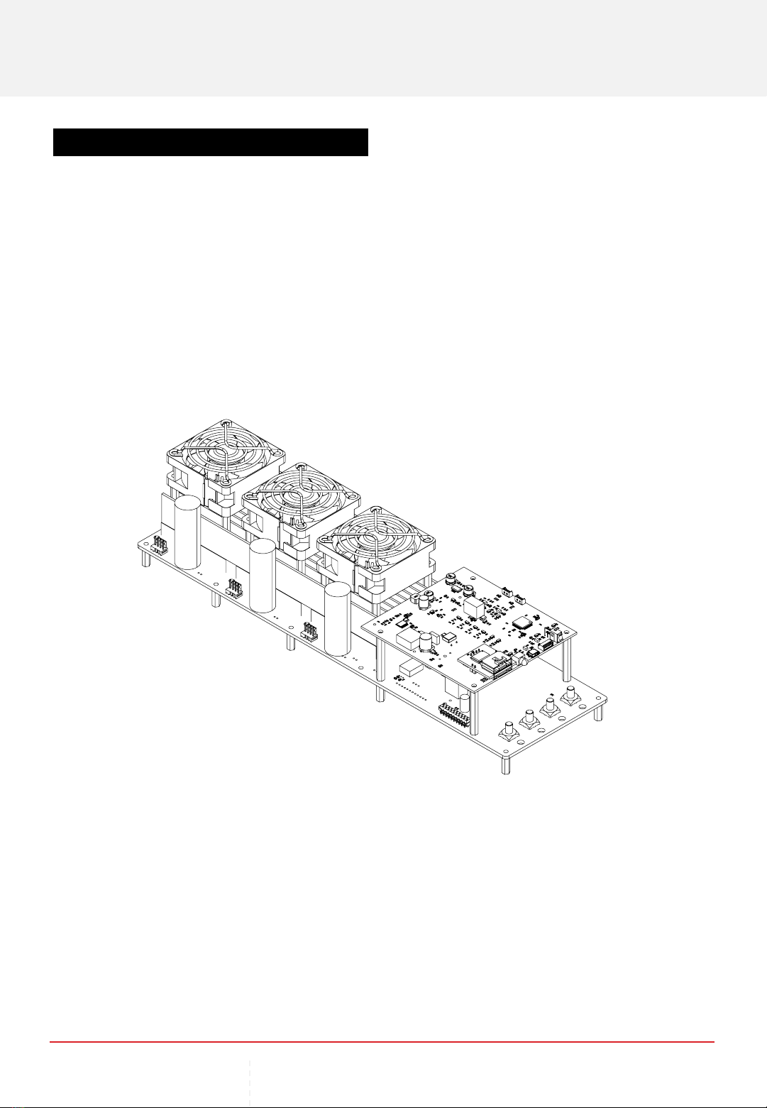
2OVERVIEW
2.1 CEREBRAL-55 SYSTEM OVERVIEW
12
Off
On
1
234
6
7
8
9
10
11
13 14 15
ITEM DESCRIPTION
1. Output On/Off Switch 6. Control board 11. Converter Board
2. Programming Port 7. Fans x3 12. GND M5 stud
3. Load VI sensing 8. DCDC Converters x3 13. V_in M5 stud
4. Supply/Battery VI sensing 9. Status LED 14. V_out M5 stud
5. UART Port 10. Mounting M3 Spacers x10 15. GND M5 stud
5

2.2 GRAPHIC USER INTERFACE (GUI) OVERVIEW
Configure CEREBRAL-55 output settings through the “Spectronik Cerebral DCDC GUI”
PC app using the USB-to-UART cable.
Tip: A terminal emulation program on a computer, such as a HyperTerminal, is an alternative.
Use com port settings: 57600 bps | 8 Data Bit | No Parity Bit | 1 Stop Bit | No Flow Control
The GUI has the following features:
I. Display input and output values.
II. Display CEREBRAL-55’s settings.
III. Display CEREBRAL-55’s operational status.
IV. Clear step-by-step user guide on how to configure settings.
V. Data-logging into CSV file.
1 2 3 4 5
6 7 8 9 10
ITEM DESCRIPTION
1. Operational Status 6. User input text box
2. Values of Inputs 7. System messages output box
3. Values of Outputs 8. Communications port drag-down selector
4. Output Settings 9. Data-logging “Save” button
5. Converter Temperature 10. System “Connect” button
CHAPTER 2 | OVERVIEW

GUI displays live status when the output Switch is turned on.
GUI displays output configurations and instructions for new settings.
CHAPTER 2 | OVERVIEW
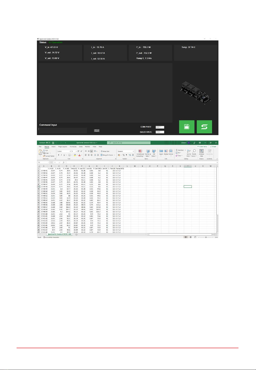
Live data-logging is available and will be saved in a CSV format.
CHAPTER 2 | OVERVIEW

CHAPTER 3 | OPERATING CEREBRAL-55
Turn on the power at source. System will boot up.
Turn Switch to ON to allow output at V_out (to load). (Output settings are set to last used
configuration. If in doubt, connect to GUI to verify output settings.)
V_out
Source CEREBRAL-55 LOAD
V_in
GND GND
3.1 GETTING STARTED (SYSTEM CONNECTIONS)
Cable lug connection with Input / Output GND
Cable lug connection from Input +to V_in
Cable lug connection to Output +from V_out
Cable lug connection with Input / Output GND
Switch = Off
LED
3OPERATING CEREBRAL-55
Communication
PC
To PC via USB-to-UART cable

Install “Spectronik Cerebral DCDC GUI” on a PC.
The GUI loader icon will be on desktop screen after installation.
(Software can be downloaded from Spectronik website.)
Connect the CEREBRAL-55 UART-Port to the PC using the USB-to-UART cable.
At the UART connection, ensure correct orientation,
Black wire to “BLACK” locator.
CHAPTER 3 | OPERATING CEREBRAL-55
3.2 GETTING STARTED (GUI SETUP)
UART Port on
Control Board
UART Console of
USB-to-UART cable
Caution
The UART connector has a tight fit to provide a robust connection.
When connecting, ensure the UART console is fully inserted into the receiving port.
When disconnecting, firmly grip the sides of the console head and pull out.
You may jiggle it sideways but not up-down.
Do not pull by the wires.

When the CEREBRAL-55 and the PC are connected,
Run the GUI.
The program windows shown below would appear.
CHAPTER 3 | OPERATING CEREBRAL-55
Select the correct communication port and click on the (Connect) button.
The GUI is now connected to the CEREBRAL-55.
GUI will respond once there is power into the CEREBRAL-55.
Note
GUI is not needed to turn on the CEREBRAL-55.
GUI is only needed for output setting(s) reconfigurations.
The GUI may remain connected for monitoring and datalogging.

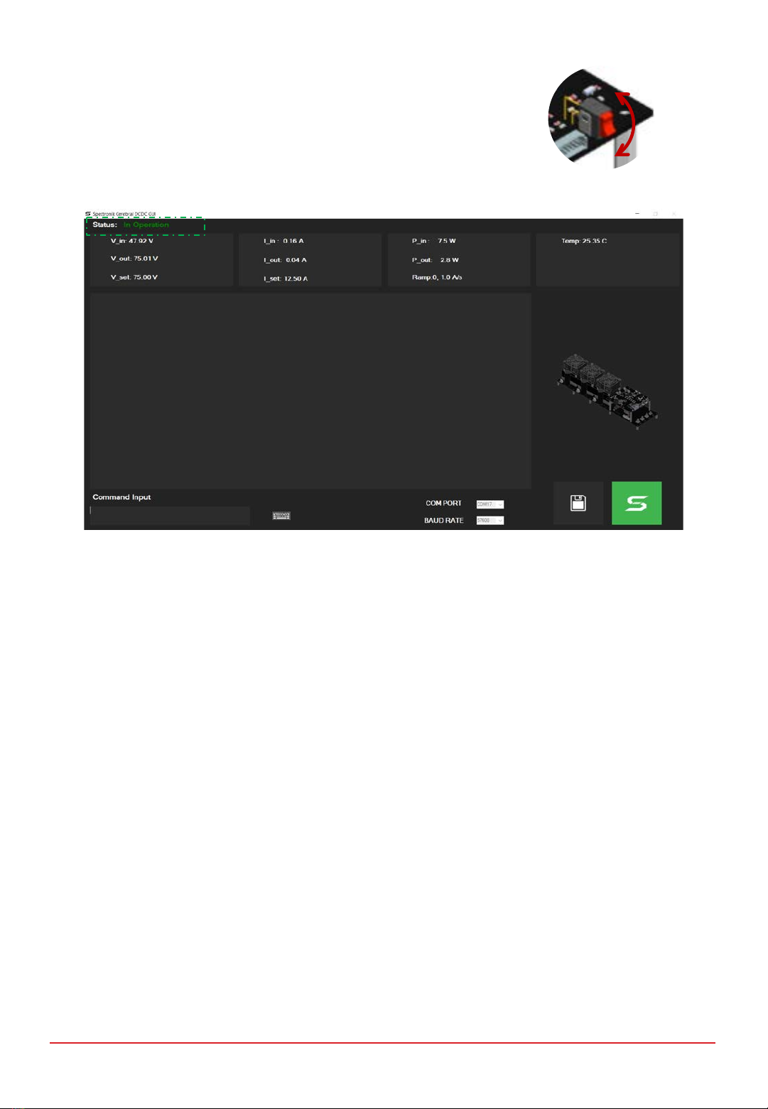
Turn on the input power (at Input +)to the CEREBRAL-55.
Input power automatically activates the system.)
The CEREBRAL-55 has entered “Standby” status, as shown on the GUI.
(If the GUI screen remains unchanged (blank), it is likely that the com port is incorrect.)
CHAPTER 3 | OPERATING CEREBRAL-55
3.3 GETTING STARTED (SYSTEM CONFIGURATION)
Keep the Switch at Off to make changes to the output settings.
Refer to the guide printed in the message box,
Follow the relevant steps to change the output setting(s).
Illustrations are available in the appendix.
CEREBRAL-55
operational range
Output configurations
Instructional guide to
change the output
configurations
CEREBRAL-55 is now ready.
(Ensure output settings are configured correctly.)
Turn Switch to On, to allow power output.
GUI will show that the system has entered “In Operation” status.
CHAPTER 3 | OPERATING CEREBRAL-55
Off
On

Turning off output
To disable output power from the CEREBRAL-55, turn Switch to Off.
The system will return to “Standby” status.
Note: CEREBRAL-55 will automatically shut down if there is no Input power.
Off
On
Aborting the GUI program
The GUI can be disconnected or terminated at anytime.
Click on the (Connect) button to end GUI.
The (Save) button must be at ‘off’ in order to end the GUI.
The “x” button on is now permitted.
3.4 SHUTTING DOWN
CHAPTER 3 | OPERATING CEREBRAL-55
“Current-Ramping” is a process to control the current increase slew rate, in a stepwise manner.
This feature is pragmatic for application where the power source prior to the DCDC converter
might not be able to provide/discharge its full power instantaneously (such as fuel cells) and
requires time to meet that capacity. This also support smoothening the transition between
multiple power sources.
The current ramping rate is configurable,
Ramping function can be set to Active or Non-active (configurable through setting)
Step length resolution = 500ms (fixed)
Step height resolution = 500mA ∼10000mA / 500ms (configurable through setting)
(Range given as 1A/s to 20A/s)
Refer to “Output Current Ramping Setting (active & non-active)” in the appendix for setup guide.
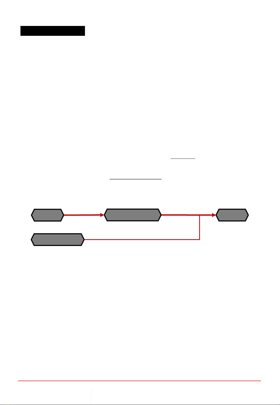
When operating with an active Current-Ramping program, it is necessary to have
an auxiliary power source (Aux_P_out), in parallel to the Cerebral-55 output (P_out).
The auxiliary power must be there to support the full power demand from the load,
while the Cerebral-55 ramps up its power output.
See example on next slide.
CHAPTER 3 | OPERATING CEREBRAL-55
P_out: 72V, > 10A
Aux_P_out: 72V, > 10A
Source CEREBRAL-55
Aux Source
LOAD
72V, 10A
> 720W
3.5 CURRENT-RAMPING
CHAPTER 3 | OPERATING CEREBRAL-55
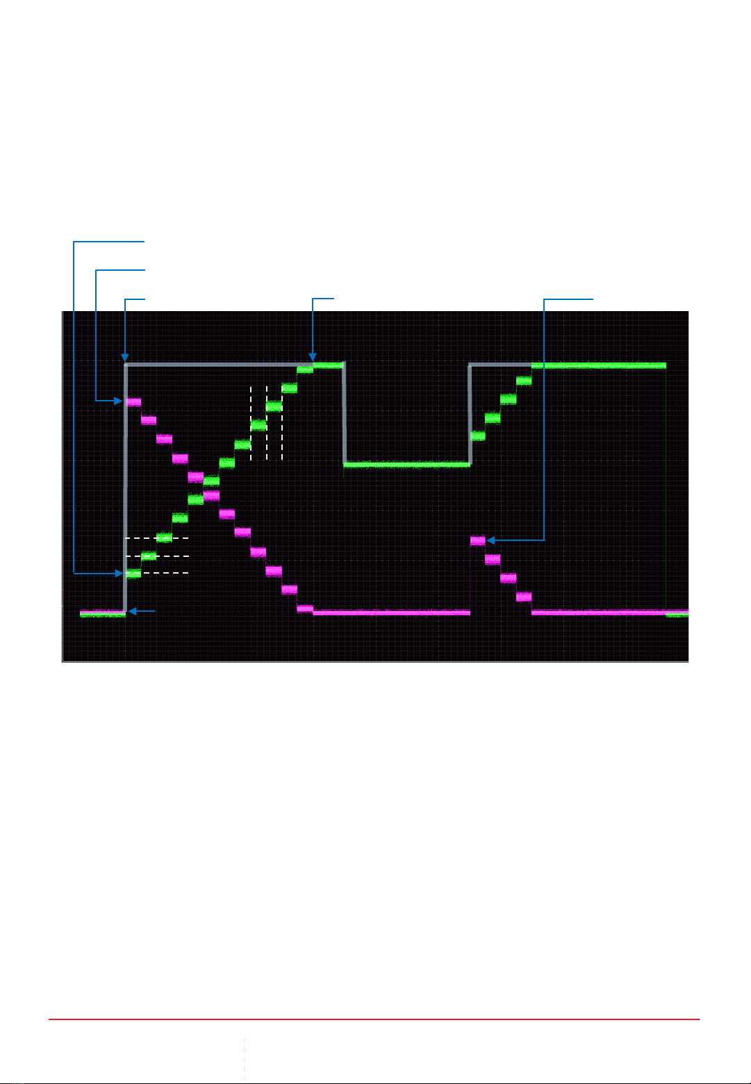
An example
Cerebral-55 Settings:
I_Set: 12.5 A, (Output I Limit)
Ramp: 1, 1.5 A/s
∴step resolution →750mA/500ms
Load = 10A
Load engaged
min Output I Limit = 2A (default)
I_out &Aux_I_out = 0A0A
Aux_I_out contribution = 8A
Ramping reached 10A
Load ↓= 6A
Load ↑= 10A
Aux_I_out = 4A
750 mA
500 ms
Electronic-Load:
Mode: Constant-Current
(For steady current demonstration)
Load: 10 A
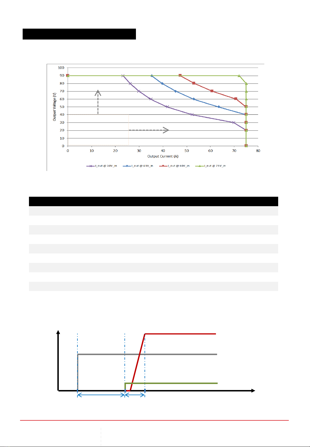
VI Characteristic of Input & Output relations Graph
Efficiency reference Table
3.6 PERFORMANCE GRAPHS &TABLES
CHAPTER 3 | OPERATING CEREBRAL-55
Increase Current Limit
Increase Voltage Setting
V_in V_set V_out I_in I_out P_in P_out Effi Notes
15 24 24.04 71.80 40.99 1077.00 985.40 91.49 Low-low buck
24 15 15.00 50.70 74.49 1216.80 1117.35 91.83 Low-low boost
24 48 47.68 75.10 35.39 1802.40 1687.40 93.62 Low-mid boost
48 24 23.81 38.90 73.99 1867.20 1761.70 94.35 Mid-low buck
48 48 47.19 75.00 73.29 3600.00 3458.56 96.07 Mid-mid buck/boost
15 90 89.60 75.40 10.89 1131.00 975.74 86.27 Low-high boost
90 15 15.05 14.00 73.99 1260.00 1113.55 88.38 High-low buck
48 80 79.10 75.50 43.99 3624.00 3479.61 96.02 Mid-high boost
80 48 47.14 45.30 73.99 3624.00 3487.89 96.24 High-mid buck
80 80 78.50 67.30 66.99 5384.00 5258.72 97.67 High-high buck/boost
Startup Duration Graph
t
V
V_in
V_out & I_out
max output
Switch = On
1200ms
Boot-up
500ms
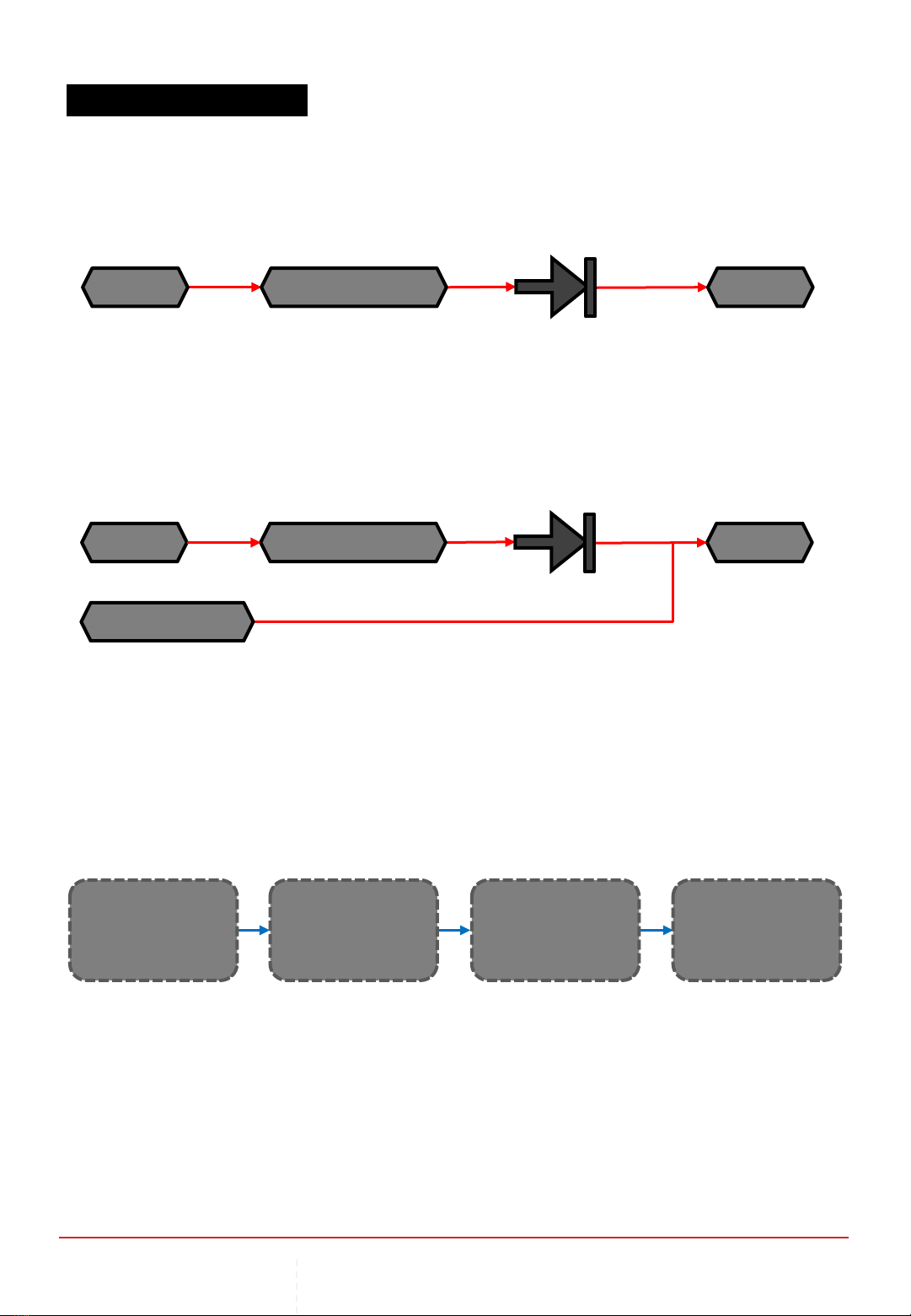
3.7 SYSTEM INTEGRATIONS
When integrating with another source of power in parallel to the converter output,
A Diode at the converter output must be in place.
*And depending on the type and function of the parallel source, it may require a diode as well.
P_out
Aux_P_out
Source CEREBRAL-55
Aux Source
LOAD
Diode
With Parallel Power Source(s)
Requirement:
70V, 60A
(4200W)
Voltage-drop:
-0.3V
Output setting:
V_set = 70.3V
I_set = 60A
Counter V drop
= 70V + 0.3V
= 70.3V, 60A
( = 4218W)
LOAD Diode
Assume 96%
efficient.
Required Input W
= 4218/96%
( = 4394W)
CEREBRAL-55
Obligation:
(>4394W)
Source
Work backwards to determine power requirements and obligations on respective segments.
An example:
Sizing up Power Requirements in an Integration
Stand-Alone Power Source
If the load is capable of generating a potential,
A Diode at the converter output must be in place.
P_out
Source CEREBRAL-55 LOAD
Diode
Recommended Diode
Peak Reverse Voltage: 170V
Max Forward Current: 100A
Reference diode model: STPS200170
CHAPTER 3 | OPERATING CEREBRAL-55
CHAPTER 4 | MECHANICAL DRAWINGS
4MECHANICAL DRAWINGS
4.1 MECHANICAL DRAWINGS –CEREBRAL-55
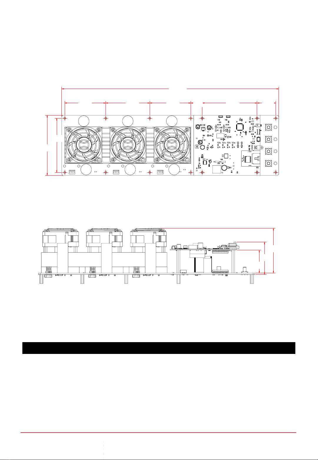
A
B
I
CD E F G H
J
K
L
All dimensions in mm
A100.00 G91.00
B90.00 H31.00
C68.00 I360.00
D73.00 J40.00
E68.00 K54.30
F19.00 L75.20
CHAPTER 4 | MECHANICAL DRAWINGS
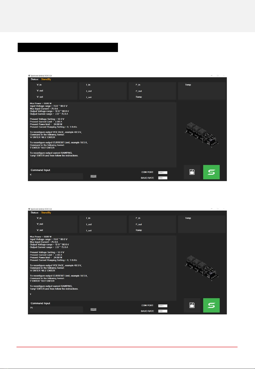
5APPENDIX
5.1 APPENDIX –OUTPUT VOLTAGE SETTING
Type in “v” into the input text box, followed by the “enter” key.
Type in desired voltage, e.g. “75”, and “enter”.
CHAPTER 5 | APPENDIX
Table of contents
Popular Media Converter manuals by other brands

Vanco
Vanco 12x3 Multi-Function Switch/Scaler Technical support

AJA
AJA Hi5-4K Installation and operation guide

AJA
AJA FiDO-TR-12G Installation and operation guide

DJ-Tech
DJ-Tech cd encoder 10 user manual

Meridian
Meridian Ultra user guide

ProVideoInstruments
ProVideoInstruments VECOAX ULTRA BT Series manual

Ltech
Ltech LT-DMX-6803 user manual

Omnitron
Omnitron iConverter GM3 quick start guide

CIS
CIS CL-OPT200T Product specification & operation manual

Panduit
Panduit Atlona AT-HDVS-SC-RX manual

Renishaw
Renishaw QUANTiC RTLC40-S installation guide

Absolute Process Instruments
Absolute Process Instruments DuoPak APD 2000 manual


